6BL8 Amplifier Test Panel.
6BL8 Amplifier Test Panel.
Circuits using the 6BL8/ECF80 as an audio
amplifier have already been mentioned here
and here. In this
article, a more detailed investigation was made into the operating conditions
to see if in fact the valve was operating within ratings, and that maximum
output was being obtained.
Why use a 6BL8 as an audio amplifier?
The answer to that is that they are an extremely common TV valve, which
most enthusiasts in Australia have copious quantities of. Most people see
them as worthless, but as will be shown, they make a compact amplifier
ideal for use in small receivers. Europeans will be more familiar with
this valve in its series heater form; the PCF80 or 9A8. The characteristics
are identical, except of course for the heater.
In the U.S., the 6BL8 is not so common,
but there the 6U8/ECF82 is their equivalent 'worthless TV valve'. The 6U8
is used for the same applications and even has the same pin connections.
There are differences in the characteristics, but they are close enough
to suit the amplifier circuit to be described, with a minor modification.
The 9U8/PCF82 is the 300mA series heater version.
The next part of the design is the output
transformer. Given the valve will cost nothing, or next to nothing, the
transformer should also be inexpensive and readily available. The Jaycar
MM1900 speaker transformer is ideal for this amplifier, since it has a
suitable impedance ratio, and there is not enough plate current in this
circuit to cause problems with core saturation. For those not familiar
with the MM1900, it is designed to operate 8 ohm speakers from 100V lines
used with public address systems. Conveniently, the impedance ratios of
such transformers happen to suit valve circuitry, but with
a catch. They are not designed to have DC passed through their windings.
When used in a single ended output stage, the plate current will cause
core magnetisation. Transformers designed for such use have the laminations
arranged to include an air gap, which prevents saturation. P.A. line transformers
do not have an air gap, and it has been found that to use them successfully
that the output stage needs to be a triode, and/or the plate current kept
very low relative to the core size.
For the less than 10mA plate current drawn
by the 6BL8 or 6U8, core saturation did not appear to be problematic.
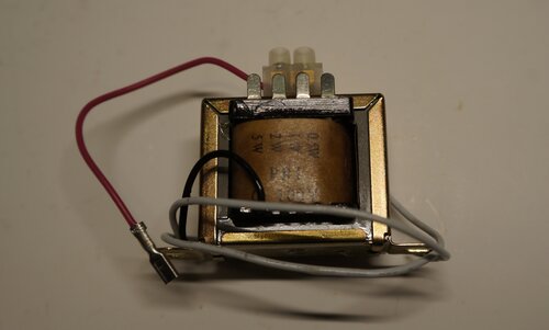
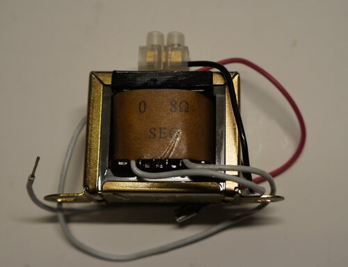
MM1900 Transformer suits low powered valve output stages.
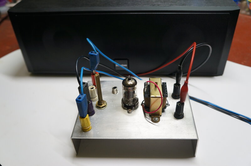
As with the super-regenerative receivers developed of late, it was decided to make up a test panel with terminals and a nine pin valve socket, so that various aspects of the design could be easily altered and experimented with.
1. 6BL8 Triode Output Stage.
The first experiment was to find out what
the triode was capable of as an output stage. The maximum plate dissipation
is 1.5W, so the ultimate operating conditions have to consider this, as
well as the impedance ratios available from the MM1900.
| B+ | 150V | 200V | 210V | 220V |
| Vk (quiescent) | 6.4V | 8.5V | 9.2V | 9.4V |
| Ik (quiescent) | 6.4mA (Rk 1K) | 7mA | 7.7mA | 7.8mA |
| Plate dissipation (quiescent) | 927mW | 1.3W | 1.52W | 1.63W |
| Power output | 116mW | 209mW | not measured | 228mW |
| Vk (full power) | 6.6V | 9V | 9.6V | 9.9V |
| Ik (full power) | 6.6mA (Rk 1K) | 7.5mA | 8mA | 8.25mA |
| Plate dissipation (full power) | 970mW | 1.4W | 1.6W | 1.72W |
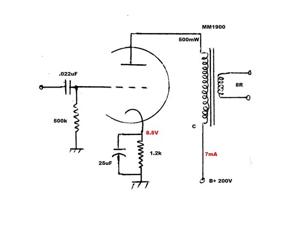
Maximum undistorted output was obtained
from the 500mW primary tapping on the transformer. The transformer in all
the experiments was loaded with an 8.2R resistor. This appears as an impedance
of 24k at the primary.
As can be seen, the B+ needs to be no
more than 200V to safely keep within the 1.5W plate dissipation. At 200V,
the plate dissipation is 1.4W with full output. Audio output power into
the 8.2R resistor is 209mW.
The input signal to produce full output
is 18Vp-p (6.3Vrms).
The low output power and high input signal
required was no surprise, given the inefficiency of triodes as output valves.
No further investigation was done with triode operation, since the 6BL8
contains a pentode which should be much more efficient in this role.
Since it was convenient to do so, the triode output stage was tested with 12V B+. No bias was used. Maximum output was 5.3mW with the 2W primary tapping. This seemed promising, until it was found that the grid had to be driven directly from the low impedance of the signal generator. This was necessary to drive the grid positive. A high impedance drive, such as from a resistance coupled amplifier, just couldn't produce any useful power. This mode of operation has been discussed here.
2. 6BL8 Pentode Output Stage.
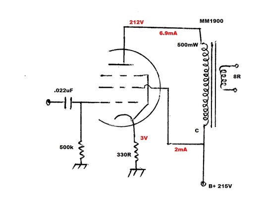
The two important parameters here are
the plate dissipation of 1.7W, and the screen grid dissipation of 500mW.
The maximum cathode current must not exceed 14mA.
Again, with the plate currents used, the
500mW (24k) tapping was found to provide the best matching. Note that when
used with 8 ohms, the primary impedance is closer to 20k.
Experimenting with the bias, and keeping
an eye on the dissipations, the best compromise turned out to be that shown
above.
The plate dissipation is 209V x 6.9mA
= 1.45W
The screen grid dissipation is 212 x 2mA
= 424mW
Keep in mind the screen and plate voltages
are measured relative to the cathode, hence the discrepancy with the voltages
used for the calculations.
Total current at 215V is 9mA.
Input sensitivity is 8Vp-p with no cathode
bypass, and 2.6Vp-p with a bypass. While the cathode bypass increases gain,
it also increased distortion. The undistorted output power was 224mW with
no bypass, but with the bypass only 192mW was available before distortion
became obvious in the output waveform. The lower sensitivity without bypassing
was not seen as a limitation, since the triode stage would make up for
that.
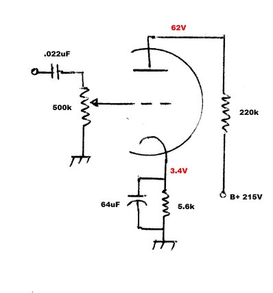
The next part of the amplifier design
was to provide a voltage amplifier, so that the pentode can be driven from
line level inputs. There is nothing critical about this, and the plate
resistor was chosen as 220k simply because of convention; being a compromise
between high gain and the loading by the following grid resistor. The bias
voltage was chosen to provide the maximum undistorted signal at the plate.
This was not critical, and a 5.6k cathode resistor was satisfactory. In
order to obtain the maximum gain, the cathode was bypassed. 64uF might
seem unusually high, but was conveniently to hand. 25uF is quite adequate.
Maximum undistorted plate voltage was
23Vp-p with an input of 1.78Vp-p. The voltage gain is only 12.9, but the
6BL8 triode has a mu of only 20.
3. Complete 6BL8 Amplifier.
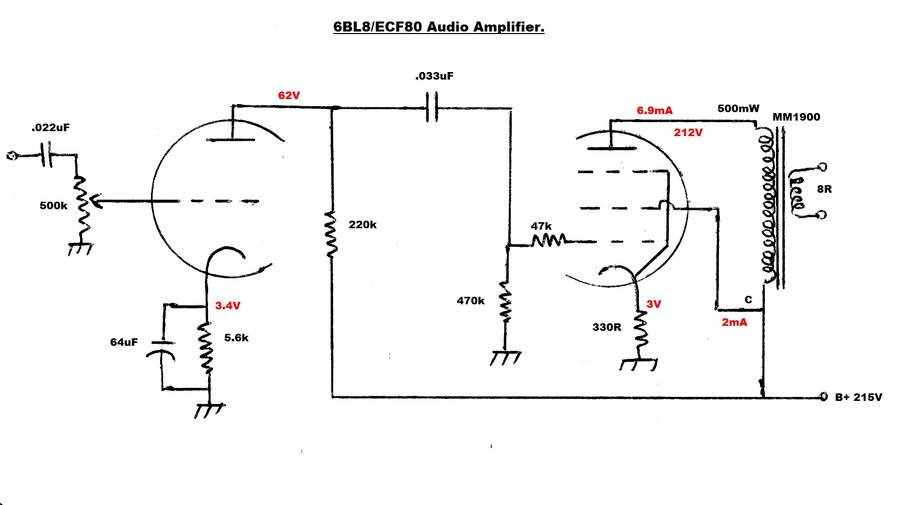
The complete amplifier has an input sensitivity
of 708mVp-p (250mVrms), and an output power of 258mW into 8.2R.
With the higher gain of the circuit, it
was considered wise to include the 47k grid stopper for the pentode. This
acts as a low pass filter in conjunction with the grid capacitance, and
ensures stability against high frequency oscillation.
A pentode plate bypass capacitor was experimented
with, and the frequency response was measured.
| No bypass | 1000pF | 3300pF | |
| Lower 3dB | 760c/s | 580c/s | 430c/s |
| Upper 3dB | 55Kc/s | 9Kc/s | 3.2Kc/s |
| Peak | 18.5Kc/s | 3.2Kc/s | 1.3Kc/s |
Presumably because of core saturation,
the lower 3dB frequency is higher than desirable. The peak frequency response
is likely to come from the primary inductance resonating with the bypass
capacitor. It was particularly noticeable with the 3300pF capacitor.
So, why include a plate bypass? With some
amplifiers it helps with stability, and corrects (in a crude way) the rising
frequency response common to pentode output stages which don't include
negative feedback. It was tested with this amplifier, because when fed
from a super-regenerative receiver, there was a high level of quench in
the plate signal, and it was felt that this might be overloading the amplifier,
reducing its output.
Further examination revealed this not
to be so, and that it was also completely stable without it. And, as can
be seen from the table, the frequency response is best with no bypass.
If a plate bypass is wanted, 1000pF is probably the best all round value.
Those who like top cut tone controls can
experiment further here with a rheostat in series with the capacitor.
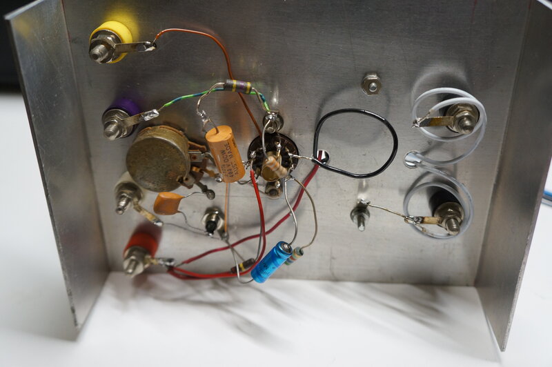
No attempt was made to improve the layout since this is a test panel.
The question of bypassing the pentode cathode
was tested again with the complete amplifier. With a 25uF bypass, the input
sensitivity increased to 70mVrms, but with obvious distortion. To improve
on this, plate to plate feedback was tried. Here, a resistor is connected
between the triode and pentode plates which creates shunt feedback. A portion
of the pentode plate voltage is fed back into its grid by this means. Since
the plate is out of phase with the grid, gain is reduced. With a 3.3M resistor,
input sensitivity was 100mVrms, and with a 2.2M it was 110mVrms. As expected,
distortion was less than with no feedback.
The circuit is best used with no cathode
bypass for maximum quality, but if a higher gain is required, use the cathode
bypass and also include a feedback resistor of 2.2M to 3.3M.
4. 6U8 Pentode Output Stage.
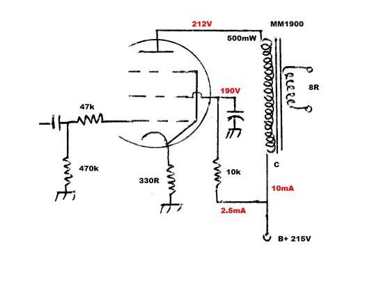
The triode voltage amplifier worked satisfactorily
with no modification, so the pentode operating conditions were next examined.
With the 6U8 simply plugged into the socket and operated with the same
215V supply, maximum output was 380mW with a sensitivity of 250mV.
The pentode plate current was 10mA, and
the screen grid current was 2.84mA. The plate dissipation was 208 x 10mA
= 2.08W, which is well within the 3W rating.
However, the screen grid dissipation was
a bit on the high side, at 211 x 2.84mA = 600mW. This is outside the 550mW
maximum rating.
By reducing the screen grid voltage to
190V (186V relative to cathode), the screen grid current was 2.46mA, which
results in a dissipation of 460mW. The screen current rises to 2.95mA at
full output, which then results in a dissipation of 530mW.
The easiest way to drop the screen grid
voltage is with a 10k resistor. The bypass is optional, but results in
a slight increase in gain if it is included. Its value is not critical
and something around 10uF will do. Of course, if the rest of the circuitry
this amplifier is to be used with has an existing 190V supply, this can
be used instead to supply the screen grid.
The whole amplifier can be run off 190V, eliminating the screen grid resistor. In this case, output power is reduced to 340mW and B+ current is 10.6mA.
Conclusion.
The 6BL8 and 6U8 make a versatile low
power amplifier, useful for small receivers or where B+ current is limited.
Sensitivity is the usual line level of around 250mV, although this can
be increased to 70mV if higher distortion is acceptable.
Given a choice of valves, the 6U8 gives
a greater output, but the 6BL8 is still useful and comparable to the output
of a portable radio. Importantly, both types of valve are common, and if
they have to be bought, are inexpensive. Similarly, the speaker transformer
is easily available and inexpensive.