Commercially made Fremodyne receivers were
manufactured from late 1947 to around 1949. As such, the same procedure
for restoration is required as with any similarly aged vintage electronic
equipment.
Typically, carbon resistors can be assumed
to have drifted high, paper condensers will be leaky, and electrolytics
will have dried out or have excessive leakage.
More specifically, in the case of the Fremodyne, let's see what needs to be done.
Where the condensers are ceramic or mica,
none of these has been found to be troublesome in any Fremodyne restored
so far. The others may include paper types, and where this is so they will
need replacement. Likewise, the 10uF electrolytic is not above suspicion.
It should at least be tested if it is wished to retain it for reasons of
originality. Some have been found to be faulty.
Turning now to the resistors, the 150k
is critical, and is of high enough value to be suspect. The 100k similarly
may have drifted high, but its value is not so critical, since it performs
de-emphasis and quench filtering. It does not affect the super-regenerative
operation.
The other resistors; 22k, 15k, and 1.5k,
are low enough not to give trouble. Likewise, the 100R B+ decoupler for
the local oscillator can be assumed to be OK.
Critical Components.
For the local oscillator, some variation
in the 20pF and 22k grid leak components is acceptable, and indeed do vary
with some manufacturers. The circuit is a very simple oscillator, and the
components are not unduly critical in terms of reliable oscillation, and
producing a suitable output level. Of course, if the 20pF is thermally
sensitive, it may cause tuning drift.
The 2pf coupling between the local oscillator
and input of the super-regenerator is important since it controls the amount
of injection, and thus how effectively the superheterodyne frequency conversion
occurs. If the local oscillator injection is too low, receiver sensitivity
is reduced. In some sets, this condenser is of the "gimmick" type; i.e.
two insulated wires twisted together. It has been found in at least once
instance the amount of capacitance was insufficient. Upon increasing it,
normal sensitivity was obtained. The "Electronics Australia" circuit has
unfortunately not included any coupling condenser, instead relying only
on stray capacitance. If constructed to the design presented, it has poor
sensitivity.
Turning now to the super-regenerator, anything
that upsets the stabilisation or quench waveform circuits will have a marked
effect on performance. It is important to note that the presence of the
super-regenerative rushing sound does not automatically indicate
the circuit is operating correctly.
The 150k resistor is part of the grid
stabilising circuit. It also has some effect on quenching frequency. If
it has drifted high, the quench frequency will be lower than normal, and
if sufficiently low will become audible. The effect of this is a whistling
sound always evident, even with the set not receiving a signal. In the
modern day, the quench frequency is important because of the presence of
the stereo pilot tone at 19kc/s. If, for example, the quench frequency
is 20kc/s, a 1kc/s tone will always be heard when the set is tuned to a
station transmitting stereo (which is most of them). Since a super-regenerative
receiver is going in and out of oscillation at the rate of the quench frequency,
it follows that any demodulated audio will be mixed with this, producing
the usual sum and difference frequencies.
The 2500pf, two 5000pF's, 10uF, and 1.5k
are also important since they control how the quenching circuit works.
It is not sufficient merely to get the circuit quenching to make the receiver
function. The quench waveform and frequency has considerable effect on
receiver sensitivity, bandwidth, and sound quality. If the 2500pF has to
be replaced note that it is not a preferred value. Initially, it should
be replaced with .0022uF or .0027uF, the quench frequency checked, and
further adjustment made if necessary. The 5000pF can be replaced with 4700pF.
Stereo Pilot Tone.
If the stereo pilot tone is making itself
evident, it is necessary to raise the quench frequency slightly; usually
to about 32-35k/cs. This is done simply by reducing the value of the 150k.
The easiest way to do this is to simply connect a high value resistor in
parallel with it. Do not reduce the 150k more than necessary, since it
could affect the stabilisation, and also raising the quench frequency reduces
sensitivity and output. Alternatively, the 2500pF can be altered, as explained
previously.
Alignment.
Since the Fremodyne is an AM superhet,
it is lined up in exactly the same way as any other conventional set. If
no alignment instructions for the set in question are available, the following
will suffice:
Feed an AM signal into the aerial terminal
at the required IF, usually 21.75Mc/s. Typically, a level of 100uV and
40% modulation is a good starting point. Adjust the IF coil for maximum
output which will also be coincident with minimum super-regenerative rush.
As always, using the weakest possible input signal will make the tuning
peak more obvious.
Next is to adjust the local oscillator. The turns of the oscillator coil are spread to increase frequency, or brought together to reduce it. This is done at the 88Mc/s end of the band. Since commercially made sets have a calibrated dial, the action of the pointer should be checked first to see it has equal overlap at both ends of the dial (unless there are markings to indicate otherwise). With the pointer at 88Mc/s, the oscillator coil is adjusted so that 88Mc/s is received at this point. Then increase the signal generator to 108Mc/s, and set the dial to this frequency. Set the trimmer capacitor so the signal generator is heard at this dial position. It will probably be found that going back to 88Mc/s, the calibration has now changed. It will be necessary to repeat this procedure several times. Be aware that given the cost cutting aspect of most Fremodynes, the dial calibrations are not always perfectly accurate. The important thing is to get it as best as possible, making sure the full 88-108Mc/s band is receivable.
The final adjustment is the aerial coil. Since the loading of this by any external aerial alters its resonant frequency, the most accurate results will be obtained by connecting the set to the aerial it will be used with. The procedure is similar to the local oscillator, in that spreading or contracting the coil affects the low end of the band, and the trimmer, the top end. Allow the signal generator to radiate into a piece of wire, for example, so that it can be heard with the aerial connected to the Fremodyne. At the 88Mc/s end of the band, adjust the aerial coil for maximum gain. Note that because of the coupling between the aerial and oscillator coils, any adjustment to the aerial circuit will cause a slight shift in local oscillator frequency. Therefore, the tuning control needs to be rocked back and forth while adjusting the aerial circuit. Again, use the minimum signal from the generator to make the peak obvious. Then, at the 108Mc/s end of the band, adjust the aerial trimmer for maximum gain, similarly rocking the tuning control back and forth to find where it peaks. As before, the procedure will need to be repeated a few times, but note that the peak is fairly broad.
While this sounds complicated, in actual fact the aerial circuit response is quite broad, and it is not as critical as the local oscillator. In fact, it is doubtful that perfect tracking will be obtained anyway since some Fremodynes don't include any local oscillator padding circuit.
In practice, the set shouldn't have to be aligned except unless it's been "got at", or parts affecting the tuned circuits have been replaced. Usually, the most that is required is the trimmer adjustments.
Local Oscillator.
As noted with the Howard
474, and Olympic
sets, the Fremodyne is mounted on a sub chassis mechanically isolated
from the main chassis with rubber grommets. A copper braid connects the
two for the earth connection. Unfortunately, in all examples of these sets
so far restored, this connection is sufficient to cause the local oscillator
to drop out at the top end of the FM band. It has been necessary to add
extra braid connected to different points. In this regard, a spectrum analyser
is invaluable for observing the local oscillator performance - and the
effect of adding the extra braid is clearly obvious.
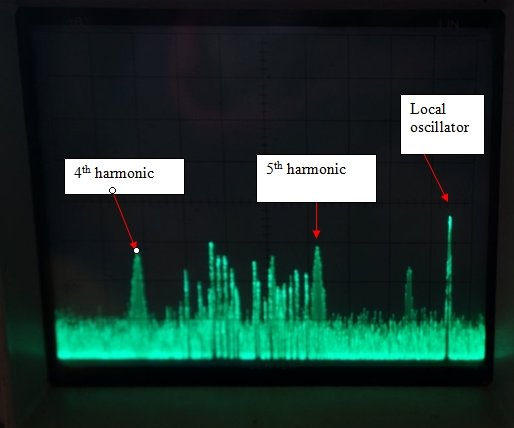
Spectrum analyser shows local oscillator and super-regenerator activity.
However, the real problem is the local oscillator circuit used by some manufacturers. By design, it is barely able to oscillate, and anything not 'just so' will cause erratic behaviour. The earthing arrangements of live chassis sets using an isolated B+ busbar are not perfect, and any deficiency shows up by an already weak oscillator dropping out. Furthermore, the circuit is critical with the actual valves used. Some will oscillate perfectly while others refuse to, or do so erratically, despite being new examples of the same type number. One example of this is the Olympic only working with Sylvania 14F8's, and not GE or RCA.
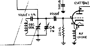
Less than full oscillator coil reaches the grid with this arrangement.
The problem occurs with sets which have
a padder capacitor in series with the tuning capacitor. If, as in the problem
sets, the oscillator grid is fed from the junction of the padder and tuning
capacitor, the grid receives reduced voltage because of the capacitive
voltage divider action. A rough calculation, assuming a 20pF tuning/trimmer
capacitance, would cause a 30% reduction in grid drive. This is discussed
in greater detail in the Olympic article.
Another local oscillator design fault,
found in the Olympic, is not only was the 14F8 heater not adequately bypassed
to earth, it was deliberately decoupled from earth with a choke! The type
of oscillator used, with a choke in the cathode circuit, is affected by
heater earthing, or lack of, since there is capacitance between the heater
and cathode.
Therefore, if restoring a Fremodyne of
this nature, and FM reception drops out at certain parts of the band this
is a likely cause.
It is worth noting that sets such as the Meck, with no padder circuit, are good performers. Similarly, the Perco, Sentinel, Heathkit, and Gilfillan sets have not had any problem.
Oscillator Injection.
Additionally, a weak local oscillator,
even though not actually dropping out, will cause reduced sensitivity.
In the same way, inadequate local oscillator injection will also cause
reduced sensitivity. In this regard, the Electronics Australia design has
poor sensitivity compared to most commercially made Fremodynes, since it
has no actual coupling capacitor, relying on valve capacitance and stray
radiation. Likewise, the Perco benefited with an increase in the value
of its "gimmick" coupling capacitor.
Choice of IF.
The choice of IF used by particular manufacturers
is not problematic except where a harmonic falls in the FM band. The super-regenerative
IF channel of the Fremodyne radiates at its own frequency, as well as those
of its harmonics. If one of these should fall in the FM band, it will be
impossible to receive anything on this frequency. Hazeltine recommended
21.75Mc/s, and most sets use this frequency. Here, the fourth harmonic
occurs at 87Mc/s, and the fifth at 108.75Mc/s; both just outside the FM
band.
28Mc/s is another suitable IF, with the
third harmonic at 84Mc/s, and the fourth at 112Mc/s.
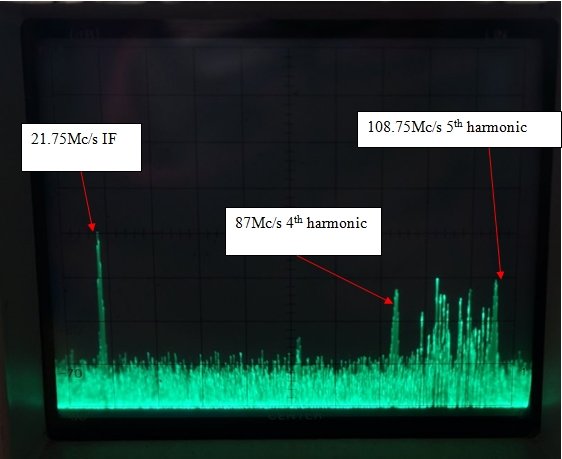
Spectrum analyser shows how the super-regenerative IF creates harmonics
which fall just outside the FM band. Obviously, an IF which creates harmonics
that fall within the band is unsuitable.
However, if you find yourself with an Audar FMC-12, you'll find reception at 93Mc/s impossible. This is because the IF is 23.25Mc/s, and the fourth harmonic is 93Mc/s. This interesting choice of IF must have gone unnoticed in the Audar design laboratories, with no local station on this frequency. It also shows the operation of the Fremodyne was not fully understood. Obviously, such a set should have the IF retuned to 21.75Mc/s. This will entail having to re-align the local oscillator slightly, of course.
Power Supply.
A minor problem with the Perco
FM tuner is the dial light circuit. As the set is designed, dial light
brilliance is nowhere near what it should be. This is because the dial
lamp is fed partly from a tapping on the the 35W4 heater, and partly from
the set's B+ current flowing through it. Since the Fremodyne tuner
on its own draws only a few milliamps, there is not enough current to give
anything like normal brilliance for the dial lamp. There is a mistake on
the published circuit diagram concerning the pin connections and dial light
tapping for the 35W4.
Magazine projects are not without out their
faults either. The simplified
Fremodyne has the valve heaters over-run since the heater string adds
up to 104V, somewhat less than the quoted 117V. There is no surge resistor
in series with the rectifier, which could shorten its life due to excessive
peak charging current of the first filter capacitor.
The Electronics
Australia design runs the Fremodyne circuit at 180V which will reduce
sensitivity, since the stabilising circuits were designed for 100V. B+
voltage is important, and the effects of changing it can clearly be shown
with a working Fremodyne.
While the Meck design is a very good performer,
some versions have the mains directly connected to the chassis. This is
dangerous since it can be touched from outside the cabinet, and to further
increase the danger, in one version, one of the terminals on the back is
connected to the mains through a 100R resistor. These sets should only
be used with an isolating transformer.
Similarly, the Perco has a non-isolated
chassis. While its aerial is isolated, the audio output is not, and one
side is connected directly to the mains. It is rather horrifying to see
recommendations of using headphones with both these sets.
Certainly for 240V operation, all sets
should only be used through an isolated step down transformer, not an auto-transformer.
What mains isolation does exist in these sets is not up to withstanding
240V. The exception is the Heathkit FM-1 which is fully transformer isolated.
Cathode Poisoning.
When a valve is operated with the heater
at normal temperature but without any cathode current being drawn, the
cathode may eventually be "poisoned" and emission will suffer. This is
a particular problem with AM/FM Fremodynes, since when the set is used
on AM, the 12AT7/7F8/14F8 receives no B+. After some time, FM reception
becomes difficult and may stop altogether, as the valve loses emission.
Conversely, when the set is used mainly on FM, the valves in the AM section
could suffer.
The way to prevent this is to ensure a
small amount of current flows when the relevant stage is not in use. By
choosing a very low current, the stage will not be active enough to risk
causing audio breakthrough. All that is required is a high value resistor
between the AM and FM sections of the B+ switching. 100k to 150k is typically
suitable. Since the AM section has sometimes been found to oscillate, since
it is being fed from a high resistance source, some RF bypassing is necessary;
typically 0.01uF to 0.1uF will do.
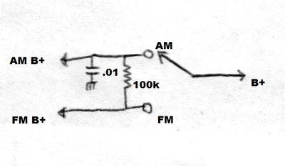
Installed in AM/FM sets, this will prevent cathode poisoning of
the valves not in use.
Update 1/2/26: The resistor may have to raised to 180k
or higher. In some sets the super-regenerative detector is still oscillating,
and the harmonics of the quench are audible when switched to AM.
The IF stage and Quench Frequency.
Generally, most manufacturers have kept
to the component values and circuit design as specified by Hazeltine, except
for the modified two choke version, and a variation in IF coil damping
resistor. No design faults have been encountered. However, it has been
found that individual valves can have considerable effect on the operation,
despite the stabilising circuits.
With the components specified, the quench
frequency should be around 30Kc/s. In practice this usually needs to be
increased to 32-35Kc/s to remove the pilot tone beat. If the quench frequency
is found to be up around 50Kc/s or even higher, other valves should be
tried.
Such a high quench frequency actually
gives the best sound quality - but at much reduced sensitivity! Therefore,
if one only listens to strong stations, an excessive quench frequency will
probably go unnoticed. However, someone might assume the Fremodyne is an
insensitive design, when they try to listen to weak stations, should such
a set be their only experience of the circuit.