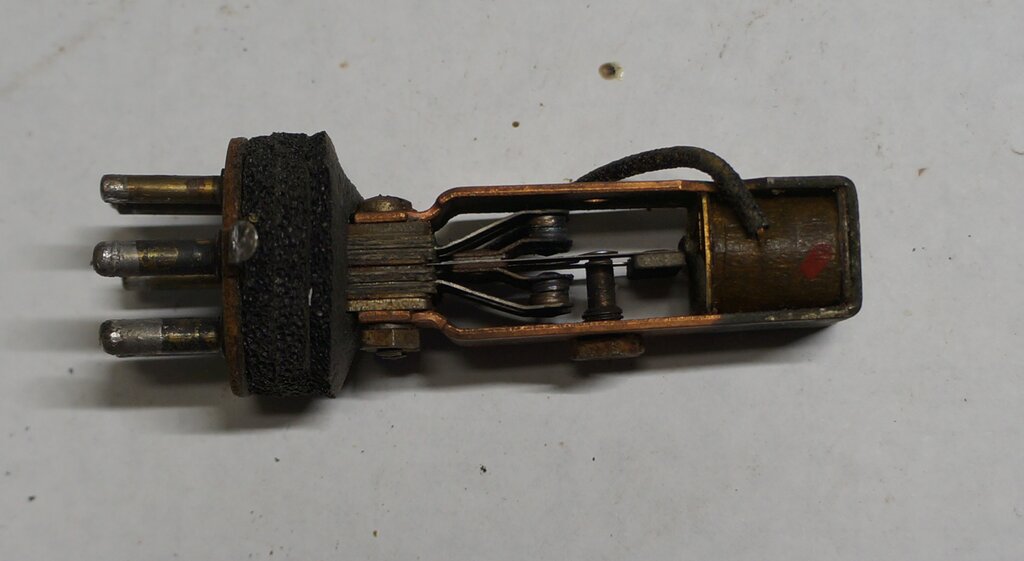
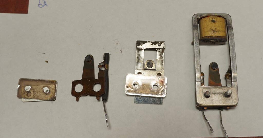
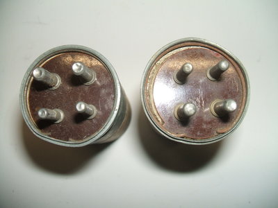
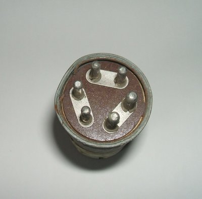
Yes, it can be restored! This Utah worked well after a good clean up.
Yes, it can be restored! This Utah worked well after a good clean
up.
When a restorer first encounters a vibrator
power supply, the usual situation is that the vibrator will not start,
if of the shunt drive type. Separate drive types will usually start, but
there may be reduced or no output.
When a vibrator has not been used for
many years, tungsten oxide can build up on the contacts. An insulating
film can also form, which is a decomposition product of the rubber can
lining.
The result is that although the contacts
physically touch, they are still insulated from each other. Obviously,
a shunt drive vibrator cannot start in this condition.
Separate drive types will usually start,
because the precious metal used for the drive contact is non-tarnishing.
However, the power contacts remain insulated and no output is produced.
Getting a vibrator started.
The film or oxide can be electrically
burned off, or it can be physically removed. A method for electrically
cleaning the contacts recommended by Mallory is shown below:
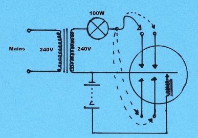
I find it more convenient to use a 240
V supply with a 100W lamp. Whether 110 or 240 V, the supply should be from
an isolating transformer. Beware that the can of many vibrators is also
connected to the reed, creating a shock hazard.
The high voltage breaks down the insulating
film which burns off. Note that the circuit is for shunt drive types.
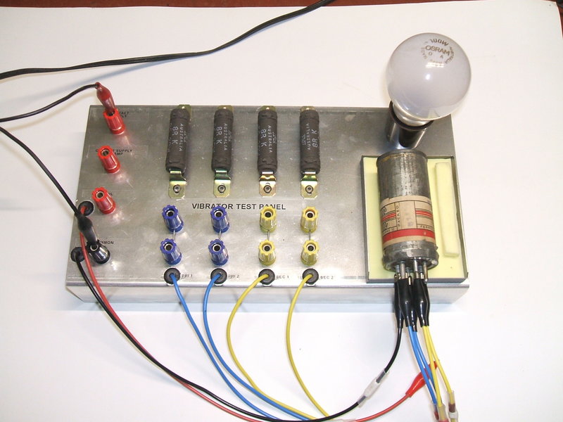
With some patience, it is often possible to get a shunt drive vibrator started with a low voltage power supply:
Low voltage power supply used to start vibrator.
The power supply is set to 30 V at 500 mA. By rapidly making and breaking the coil connection, back EMF is produced which can be high enough to break down the oxide or insulation. The power supply must be current limited, since it will be short circuited when the contact eventually makes. Provided the applications of 30 V to the coil are kept brief, it will not be harmed from overheating. It may take up to 20 minutes of making and breaking the connection to work, but is preferable to opening the can, if of the crimped type. The astute reader might wonder about using another vibrator to do the make and break job instead and the answer is yes. If neither method gets the vibrator started, chances are the contact spacing has increased too much, or the contacts are gummed up with decomposed rubber, and the vibrator will have to be opened.
In the case of synchronous shunt drive
types, once the primary contacts are cleaned, the secondary contacts should
self clean, once the vibrator is exposed to the transformer secondary voltage
of the power supply where it is used.
Alternatively, the contacts can be individually
cleaned by means of an isolated 240 V supply and 100 W light bulb as shown.
The power supply can be set to twice the rated vibrator voltage, but still
current limited, for normal running once the vibrator starts.
For split reed vibrators, the primary and secondary reeds must be connected together.
Starting Shunt Drive Synchronous
Vibrators.
If the shunt drive vibrator happens to
be synchronous, there's a useful trick that can get it started more easily
than the non-synchronous type. This takes advantage of the extra (secondary)
pull contact. Since this contact does not have the coil connected
across it, the high voltage burn off method can be used to clean it.
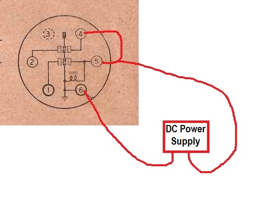
First, the secondary pull contact is cleaned.
As per the previous diagram, an isolated 240V AC supply is connected across the secondary pull contact, through a light bulb for current limiting. Next, a DC power supply is connected across the primary pull contact and coil. Since this is a shunt drive type, the voltage should be twice that of the vibrator. E.g., use 12V for a 6V vibrator. (However, the rated supply voltage will work if that's all is available). The power supply must also be current limited, in case the contacts do make connection. About 250 - 500mA will do. Now, rapidly make and break the coil connection. The idea is that the coil will pull the secondary contacts together, so that the high voltage will burn away the oxide. Once the lamp lights reliably each time the coil is actuated, it shows the contacts are now functional.
Next, the vibrator is operated using the secondary pull contact.
Since they're both in the same plane, we can now use the secondary pull contact to take place of the primary pull contact. By connecting the two together, the vibrator will now start when connected across the current limited power supply. After a while of running, the mechanical abrasion should clean the primary pull contact. You'll know when this is achieved, when the vibrator will run without the secondary contact connected. It then remains to clean both the inertia contacts with high voltage as previously described.
Starting Voltage of Shunt Drive Vibrators.
It will be seen by examination of an open
vibrator, of the shunt drive type, which no longer starts, that sudden
application of full coil voltage causes the reed to swing past the coil
pole, than if the voltage is slowly raised from 0 V. When the voltage is
applied gradually, the reed weight will be pulled over until it is opposite
the coil pole. When the voltage is applied suddenly, the reed will travel
further than the coil pole, before returning to being opposite. (In the
case of a 'good' vibrator, the effect can be demonstrated by slipping a
piece of paper between the inertia contacts to disable them). This effect
is caused by inertia of the reed weight, and is why a vibrator needs a
higher voltage to start than it does to run.
The starting voltage can be found by connecting the vibrator to a current limited power supply, and slowly raising the voltage. Once the vibrator has started, it will be seen that it will keep running when the voltage is then reduced. With very worn vibrators, the starting voltage can be higher than the rated battery voltage. There are in fact two starting voltages; one where the voltage is slowly raised, and the other being when the voltage is suddenly applied.
For a 6 V vibrator in good condition, the
'gradual' start voltage might be 4 V, the 'sudden' start voltage 3 V, and
the minimum run voltage, 1.5 V.
In worn condition, it might start when
7 V is applied gradually, but if the voltage is applied suddenly, it might
start at 5 V. The minimum run voltage might be 3 V.
In very worn condition, it might not start
at all with any amount of gradual application of voltage. What has happened
here is the inertia contacts are so worn (or out of adjustment), that connection
is not made before the reed weight is opposite the coil pole.
An example of where this can show
up is with a radio fitted to a car. It may be found that the radio works
normally when the radio is switched on, before the engine is started, but
once started the radio is no longer working. The radio has to be switched
off, then on again, to restore operation.
What has happened is the contact spacing
has increased so the run voltage is now higher than the battery voltage,
during starter motor engagement. With a 6 V system, the battery voltage
may fall to 4 V when starting. If the vibrator has worn enough so the minimum
run voltage is 3.5V, it will stop during starter motor engagement. If the
'gradual' starting voltage is 7 V, it can be seen that the vibrator will
not re-start afterwards. The 'sudden' start voltage of 5 V, will however
get the vibrator started, if the radio is switched off and then on again.
This difference between start and run voltages is particularly evident with shunt drive vibrators, since this is dependent on the condition of the contacts. It is this characteristic which draws attention to the wear of this type of vibrator, and gives plenty of warning before complete failure.
Traps for the Unwary.
Most radio vibrators are straightforward
in design; i.e. standard separate and shunt drive types. However, there
is a shunt drive type which has the drive coil brought out to a separate
pin. By connecting a resistor between this pin and the pull contact, the
vibrator can operate on higher voltages. At the rated voltage, the resistor
is replaced by a link.
The important point here is when trying
to get this type of vibrator started, one may do so in vain, unless this
is known about. Mallory 1610 and Plessey 12IHD4CS are two known types.
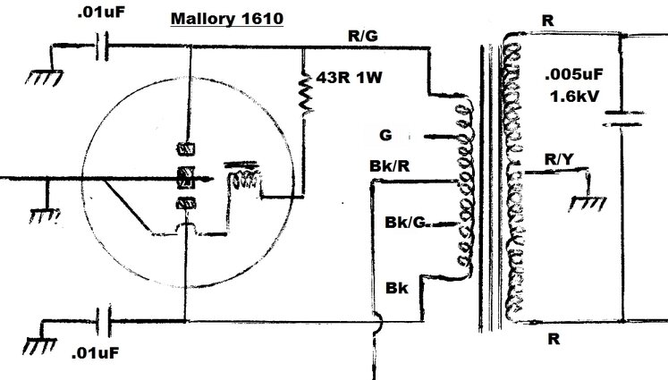
Coil connection brought out to separate pin allows 6V vibrator to
work on 12V by including the 43R resistor.
Separate drive vibrators, particularly not of the Oak type, need to be tested with caution. Sometimes the drive coil contact connection is brought out to a separate pin, to which a spark suppression network is connected. This may simply be a resistor, a capacitor, or a combination of both. The trap here is that the vibrator will appear to function normally, simply by applying the supply to the coil drive pins, but the drive coil contact will be arcing away into destruction. Mostly this type of vibrator is a high power type used with AC inverters. For example, the 12V Van Ruyten vibrators require a 0.1uF capacitor.
Some radio types also use this design. The 2 volt VB-8A and VB-8C are two known types. These require a 150R resistor across the drive coil contacts.
Contact Cleaning for Separate Drive.
Separate drive types require a separate
battery or power supply to drive the reed. This does not need to be current
limited.
Electrically cleaning the contacts of a separate drive vibrator.
Once the reed vibrating, it is a simple matter to go around each contact pin with the current limited high voltage, until the oxide is burned off.
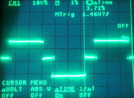
In all instances, the lamp will show a
strobing effect once the contacts are clean. This is the difference between
the reed frequency and the mains supply.
Electrically cleaning the contacts is
most successful with NOS, or long disused vibrators, which are otherwise
in good condition.
A trap is a vibrator operating in half wave because one set of contacts are not functioning. This can cause harmful arcing on the remaining contacts. That the radio plays is not sufficient indication that the vibrator is working correctly. The waveform should always be checked therefore.
Where electrically cleaning is not successful, the vibrator will have to be opened up for examination. For Oak vibrators, this involves removing the spring clip and desoldering the earth tag. Other types, such as early Ferrocarts and Van Ruytens require the base to be desoldered. Later Ferrocarts, and most foreign types require the can to be uncrimped. Unfortunately, there is no easy way to do this without some disfigurement.
I use self adhesive Aerotape foam rubber tape to replace any deteriorated rubber parts.
Base of Oak vibrator rebuilt with Aerotape.
To replace the rubber for the base of an
Oak vibrator, I use two discs of Aerotape which is about the right thickness.
Then, a third disc is made up, but with a U section cut out to slide over
the bottom of the stack, and to cover the solder tags.
If the rubber cup inside the can at the
top needs replacement, a felt disc is cut out for the top, and a strip
of Aerotape is used to line the side of the can.
It is important that the vibrator mechanism
can float, so there needs to be a gap between it and the foam rubber. In
this regard, felt is used right at the top, rather than foam, since foam
is too thick and will press against the top of the coil.
Holding the mechanism rigid interferes
with the inertia of the reed swing, and can result in reduced output, and
incorrect operation of the timing circuit.
Contact cleaning in most instances can be done with 600 grade sandpaper. Filing the contacts is required when there has been deep pitting. Even so, this should be kept to a minimum, because once filed the material is gone forever, and adjustment becomes more difficult as the contact thickness is reduced. Often, a jewellers file is sufficient, but an ignition points file works best. A problem is that the file is usually thicker than the contact spacing, so the contacts have to be disassembled.
Ferrocart vibrator dismantled for contact cleaning.
After filing, I use 600 grade sandpaper to polish the contacts.
Contact Adjustment.
The worst thing one can do is to randomly
adjust the contacts of a vibrator. Without instruments and a proper method,
there is no way of knowing if the duty cycle is correct and balanced. Disappointment
is likely to ensue, along with the conclusion that vibrators can never
be reliable. The general assumption is, unfortunately, that an apparently
simple device should only need an equally simple adjustment. However, by
now, it should be clear at least from the discussion of timing circuits,
that the adjustment is important and critical. Adjustment requires a calibrated
oscilloscope to do the job properly.
First thing to test is does the vibrator
actually need adjustment? This is going to depend on the quality of manufacture,
and the conditions it has been used in. Contact adjustment entails setting
the correct duty cycle of the primary contacts, and the timing of additional
contacts where fitted.
Most vibrators operate with a duty cycle
of 80%, and this includes the Oak and Ferrocart types, which Australian
restorers will likely encounter.
Oak details https://www.cool386.com/msp/msp.html
Ferrocart details https://www.cool386.com/vib/ferro.htm
The duty cycle can be measured in the apparatus
in which the vibrator is used. For more serious vibrator restoration, I
use a resistive test panel
https://www.cool386.com/panel/panel.html
(also described in Radio Waves, July 2019).
Test panel uses resistive load and includes bulb for contact cleaning.
Ferrocart vibrator adjusted for 80% duty cycle.
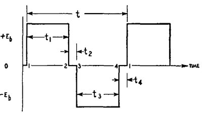
Using the above diagram, we will examine the adjustment of an Oak vibrator. The Oak runs at 100 Hz, which is a period of 10 ms. Therefore, t1 + t2 + t3 + t4 = 10 ms. Since the required duty cycle is 80%, this means t1 and t3 are each set to 4 ms.
The secondary contacts of synchronous types are set to about 2% less duty cycle than the primary contacts. In the case of the Oak, this equates to 3.8 ms.
In the case of dual interrupter and other types with multiple primary contacts, one set of contacts should be adjusted normally first, and then the other contacts timed to open and close at the same time. By using the resistive test panel, the CRO is connected between the first set of contacts on one side, and the second set of contacts on the same side. The timing difference between the two will be obvious, and the second contacts are adjusted to the point where the voltage just disappears.
What if the duty cycle is unknown? The vibrator can be tested in the power supply to which it belongs. Assuming this has been designed correctly, the timing waveform can be observed, and the duty cycle set so the practical waveform with 65% slope is obtained.
The adjustment is performed by bending
the fixed arms on Oak types. For Ferrocart, my preference is to adjust
the thickness of the mica spacers. This makes it easier to keep the contacts
parallel. If the contacts are not parallel when closed, the current will
be concentrated in a smaller area, leading to overheating, and the vibrator
will not remain in adjustment for long.
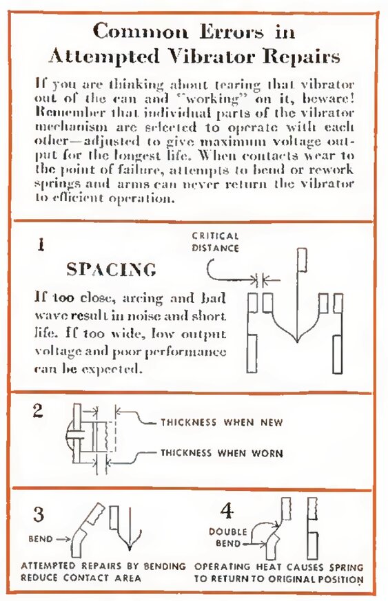
Mallory explains the problems
of bending contacts.
The above notice was issued by Mallory during the war, since some servicemen were repairing vibrators due to shortages. As most attempts at repair were without instruments, or a thorough knowledge of the subject, the adjustment under those conditions was likely to be short lived.
Can Restoration.
A common occurrence with Oak vibrators
is the base of zinc can has flared out. This is because the constant pressure
from the spring clip causes the zinc to creep over time.
Spring pressure causes zinc to creep.
It is possible to restore the original shape by rolling the end of the can firmly on a hard surface. The idea is to roll the edge so the zinc 'flows' to the opening where the earth tag is.
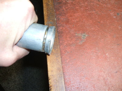
Can edge rolled against hard surface reshapes zinc.
As the zinc comes inwards, it needs somewhere to go, thus a slot needs to be cut in the can with a hacksaw. Best place to cut is in the middle of the earth tag hole. So that the earth tag can still fit, the hole will then need widening with a jeweller's file.
Slot cut allows zinc to return to original shape.
It is impossible to avoid some disfigurement to the crimped can types in opening them, but with care a reasonable job can be done. The question remains of how to put it back together. With the zinc can type, I now use the following method:
Can is easily opened again in the future if required.
Firstly, the edge of the can is flattened
out completely and tidied up. I use a short section of brass rod for this.
By placing the can on its side on a hard surface, the brass rod is hammered
against the inside of the zinc as the can is slowly rotated.
With that done, a length of tinned copper
wire of about 16 gauge is wound around the outside of the can for one turn,
to create a circle the same shape as the can. When the wire loop is placed
on the inside of the can, a short section needs to be cut out because of
the now smaller diameter.
It is used in a similar way as the spring
clip for the Oak vibrators, but is soldered against the edge of the can,
as the photo shows.
Finally, the edge of the can is tidied
up. I use a hand nibbler to remove the excess zinc, so the wire loop is
flush with the edge. The sharp edges are removed with a file.
Aluminium cans are more difficult because
they can't easily be soldered to, but the same principle can be used if
the wire loop is secured with an appropriate adhesive. I have used hot
melt glue, or alternatively, have simply secured the base back in the can
with aluminium tape.
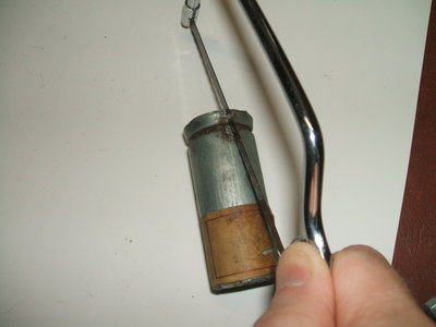
When the can is aluminium, this not very pretty, but functional,
method can be used to secure the mechanism.
Most sets using these vibrators usually have a grounding cup which holds the can in position anyway. Another method, which I have not used, is to cut the vibrator can open above the base. The can is then joined back together with a sleeve, which is hidden by the label. The sleeve is the tricky part, and for the purposes of shielding needs to maintain electrical continuity.
Substitution of Vibrators.
Aside from the mechanical considerations
of can size and diameter, and base type, vibrators are easily substituted.
A non synchronous type is the easiest to substitute, since it can be replaced
by a synchronous, split reed, or dual interrupter type. In many instances
the socket will have to be replaced, however. The additional contacts can
be paralleled for longer life, not forgetting to also connect the secondary
reed of split reed types.
Separate drive and shunt drive types can generally be interchanged without modification. The drive coil supply connection becomes redundant, in the case of a shunt drive type substituting a separate drive type, but often has to be added in the case of a separate drive type, substituting a shunt drive type. Some set manufacturers did actually include this connection to allow for a simple plug in of both types.
It is possible to use a higher voltage separate drive vibrator with a shunt drive connection, provided the vibrator will start on the lower voltage. For example, a 24 V vibrator may be used in a 12 V circuit.
Note that if substituting vibrators with different operating frequencies and duty cycles, the timing circuit must be checked, and altered if necessary. For example, a 100 Hz vibrator used in a circuit designed for a 150 Hz type may require an increase in timing capacitance, and vice versa.
Obtaining Vibrators.
From the previous notes, it should be
possible to restore a vibrators performance, unless there is serious damage,
such as a broken reed or a contact completely burned away. Alternatively,
an apparatus may have been obtained with the vibrator missing. So where
do you get another one?
Apart from HRSA meetings, I have obtained vibrators from swap meets and anywhere else junk has been sold. The Australian eBay has occasionally turned up examples at reasonable prices. By far the most reliable source is the U.S. eBay. Vibrators are always for sale, and many sellers will send overseas. Search for radio vibrator or brand name vibrator where brand name is Mallory, Oak, Utah, Cornell Dubilier, Motorola or Radiart. There are many other brands, but those will give a starting point.
This box was bought for US$14.00.
However, few U.S. types are a direct substitute
for local types, and one must be prepared to do some modification Most
are 6 V, since 12 V cars were not standard until 1954 in that country.
Also, since most U.S. types are shunt drive, the use of a series resistor
for 12 V use is impractical. One common exception is the Mallory 1701A,
which is separate drive, and requires a 15 ohm 5 W resistor for 12 V use.
This is a split reed, dual interrupter type.
Most U.S. types have a can diameter of
1.5, so allowance has to be made where a grounding cup is used with a
locally made Oak, which has a can diameter of 1.25. Ferrocart types are
1.5.
The cheapest way to buy vibrators this
way is when a bulk lot comes up. By shopping around, such a lot works out
so the individual vibrators are only a few dollars each. Postage is of
course another matter, but can be quite reasonable with a large quantity.
Oak substitutes for Ferrocart.
Given the less than optimum reliability
of the later Ferrocart non synchronous vibrators, AWA created a substitute,
unique to Australia. These are Oak types V4010, V4016, and V4011, V4017.
While designed to be a plug in replacement
for shunt drive Ferrocarts, they are internally separate drive.
Oak separate drive vibrator for shunt drive circuits.
Vibrator Transformers.
For the most part, transformers are trouble
free. Out of probably more than 100 vibrator sets, I can recall only three
transformers with shorted turns.
If one is not keen on rewinding an original,
and originality does not matter, it is usually possible to use a common
240 V transformer in reverse.
To do so requires an understanding of
timing circuits and transformer operating conditions. While it is a simple
matter to use any transformer of the correct turns ratio, to get the required
output, vibrator life will be shortened if conditions are not correct.
Factors such as magnetising current and core saturation can be problematic.
In general, toroidal types have been found
to be excellent substitutes, and I use them in new projects. However, it
is beyond the scope of this article to go into the details of selecting
a specific type.
Another aspect of using a mains transformer
is that full wave centre tap rectification is no longer possible, and the
rectifier has to be replaced by a bridge configuration. An exception is
where the set is of the battery valve type with a 90V B+. Here, a transformer
with a 120 0 120 V primary can be used.
Where one side of a vibrator transformer secondary is open circuit, it is possible to use the remaining good half with a bridge rectifier. In using the transformer this way, the timing circuit will have to be modified, with all the capacitance now connected across the good section. The capacitance will also have to be increased to compensate for the lower turns ratio.
The Timing Capacitor.
It goes without saying that any original
paper timing capacitor should be replaced as a matter of course. Because
of the high voltage AC waveform this capacitor is subjected to, the leakage
present in paper types will soon cause a breakdown.
The effect is bubbling wax, a higher than
normal current draw, and arcing vibrator contacts, while the B+ voltage
rapidly falls. Hopefully, a fuse has been fitted to save the transformer!
The best type of capacitor to use is a
2 kV polypropylene type, such as the WES Components MKP series. Dont use
250 V AC mains X2 capacitors, since their capacitance falls over time.
This comes about as the aluminium gradually burns away as part of the self
healing feature. Get some well used X2 capacitors out of old appliances
and measure their values. You may be surprised!
Life Expectancy.
Manufacturers generally do not state the
life expectancy of their vibrators, because this is dependent on operating
conditions, which the manufacturer has no control over.
Manufacturers of vibrator powered apparatus
might not always have a proper understanding of timing circuits, or the
transformer might have insufficient turns per volt or core area. Circuit
design and supply voltage variations also affect vibrator life.
The subject of life has been covered in
detail here https://www.cool386.com/vib_life/vib_life.html
Contrary to what one might expect, a synchronous vibrator operates under the most favourable conditions compared to other types. The reason for this is in how the rectification takes place. With a non synchronous vibrator, there is always a relatively high load on the primary contacts, since the rectifier charges the filter capacitors during the time at which the contacts make. The primary contacts of synchronous vibrators are under less stress, because the full primary current is not flowing during the actual contact make and break time. This is because the secondary contact timing does not permit current flow until after the primary contacts have closed, and stops it before they open.
AC inverters should in theory have the shortest vibrator life. This is because the loading is usually over most of the cycle, which prevents the timing circuit working optimally. A resistive load causes the timing capacitor to discharge much more rapidly during the vibrator dead time. Inductive loads, such as motors, have the effect of reducing timing capacitance, and capacitive loads increase it. Nevertheless, in practice, inverter vibrator life is still very good, and Ive not had to replace one.
Shunt drive types tend to have a shorter
life than separate drive, for the reasons previously discussed. However,
where the vibrator is of reputable design, (e.g. Mallory, Radiart), this
is still very good. I have used them in new projects without hesitation.
The biggest problem, as far as the Australian
restorer is concerned, is the later Ferrocart non synchronous types, used
in Astor car radios during the 1950s. Of the examples I have dealt with,
the manufacturing quality control has not always been good as it could
be, but the main problem seems to be undersize contacts. Wear is more rapid
than it should be, and being shunt drive, starting eventually becomes difficult.
However, on a positive note, I have had good results restoring them. It
remains to be seen how long they last for, before requiring further adjustment.
This type of Ferrocart usually requires restoration.
Now to the question everyone is asking;
how many hours or years can we expect?
Generally, 1000 hours has been quoted
as a minimum, but with plenty of exceptions. For example, one Radiart ad
claims at least 3000 hours, and another, if taken literally, implies over
8000 hours.
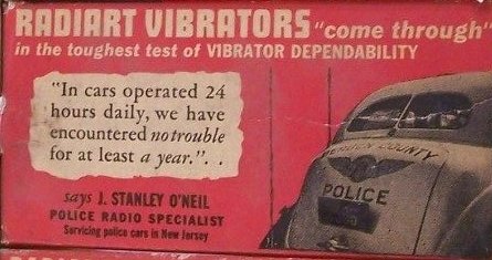
Radiart vibrator life
is very good indeed, according to this ad.
Among my own examples of vibrator powered items in regular use, the longest operating vibrator has been an Oak AV5948 in my kitchen radio. https://www.cool386.com/12v_mw_vhf/12v_mw_vhf_receiver.html
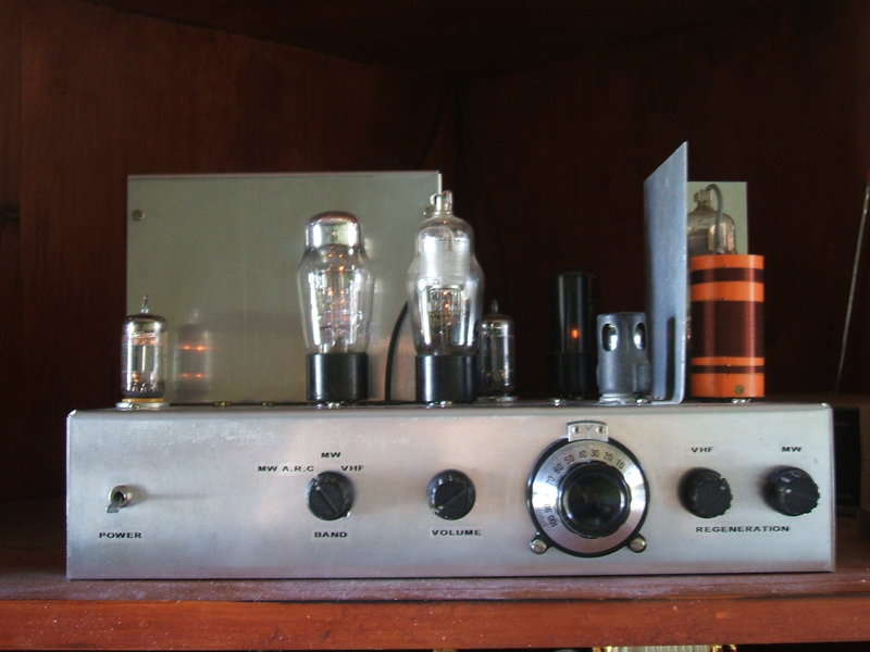
At the time of writing, the Oak
vibrator has operated almost daily for 14 years in this receiver.
In operation since 2010, for about one
hour most days, you can do the calculation yourself. The vibrator was already
used prior to building this set, and has never been adjusted. Oaks claim
of in excess of 1000 hours at 33% overload has been well and truly exceeded.
A shunt drive Mallory 245 has powered
my workshop radio without fault, since early 2019, sometimes all day, every
day. https://www.cool386.com/12v_6BL8/12v_6BL8.html
Conclusion.
Hopefully, this series has taken away
some of the apprehension of dealing with vibrator power supplies. Once
understood, they are a reliable and efficient method of power conversion.
The subject is an extensive one, and it is impossible to cover everything
in these articles. I have worked with vibrator power supplies for about
45 years, but only really understood them in the past decade or so, when
I began intensive research into the subject.
I cover numerous aspects of design and
application of vibrators on my website https://www.cool386.com for those
further interested. However, my most highly recommended text on the subject
is from the oldest and most experienced vibrator manufacturer, Mallory.
Their publication, Fundamental Principles of Vibrator Power Supply Design
can be downloaded here https://www.cool386.com/mallory/mallory_vibrator.pdf