For most vintage radio enthusiasts, AC
mains sets are the most popular, and whole collections are often based
entirely around this kind of radio. Many enthusiasts also have in their
collection, sets which operate from high and low tension batteries, either
for portability reasons, or because the technology of the time precluded
AC operation. In both instances, the design is routine and well understood.
There is also another kind of set. It
uses a vibrator power supply. Typical of these are car radios, and domestic
sets for use in areas without reticulated mains. These require only a low
tension (or A) battery. Unfortunately, these are not so well understood,
and often become a source of frustration, since their apparent simplicity
is a trap for the unwary.
Vibrators were a critical part of car radio development.
As we will see through this series of articles, there is much more to vibrators than one may initially realise, and hopefully the reader will come away at the end with a much more thorough understanding of the subject.
HT for the Car Set.
The development of the vibrator really
owes its existence to the car radio boom of the 1930s, and this is probably
the best place to begin the story.
Initially, car radios were a cross between
AC mains and battery designs. AC type valves were used since they were
rugged enough for the vibration encountered, and their heaters could cope
with the variation in voltage of the car electrical system. Typically,
a 6 volt lead acid accumulator provided the electrical needs of the car,
which was kept charged by a generator. Because of the charging characteristics
of a lead acid cell, this voltage fluctuates considerably, and a 6 V electrical
system will rise to 7 V or even higher.
As well as heater current, the valves
in the receiving set also require the usual high tension (or B) voltage
for the plate and screen grid circuits. Since the car only provides 6 V,
it was necessary to retain a separate battery HT supply. This was usually
135 or 180 V, made up of three or four 45 V B battery blocks.
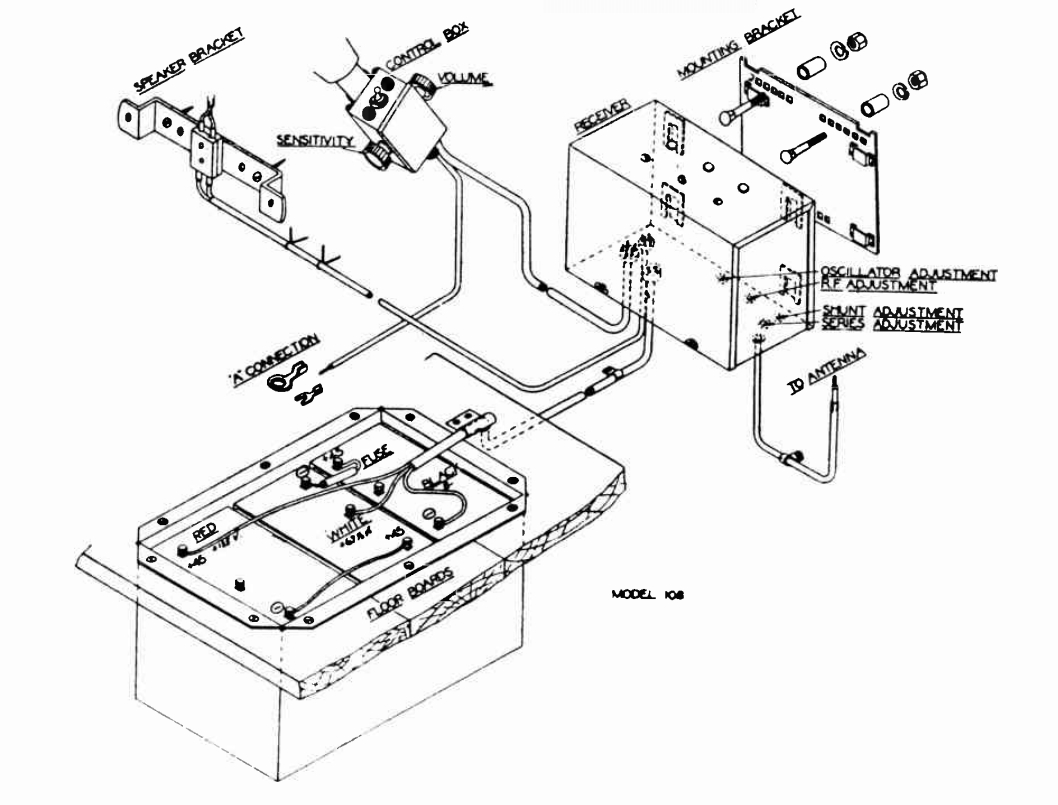
Bosch installation instructions
show the B battery box mounted in the floor.
And so for the first few years, until around
1932, car radios had a separate B battery. Just as with domestic sets,
B batteries were expensive, and required replacement several times each
year. The automotive environment also shortened B battery life, with the
vibration, heat, and unavoidable moisture ingress into the battery box,
which was usually mounted in a cut out in the rear floor section.
It can be imagined the frustration of
the motorist having to replace expensive B batteries, when there was a
seemingly endless and free source of power from the car battery.
Beginning around 1930, attempts were made
to solve just this problem. The difficulty of course, was that the car
electrical system was DC, and this cannot be simply fed into a transformer,
with the requisite 180 V coming out the other side.
Rotary Converters.
One group of manufacturers used a motor
powered from the 6 V DC, to which was coupled by a common shaft, a higher
voltage DC generator. A refinement was for both low and high voltage windings
to be on a common armature. Indeed, this was a practical and popular method,
and such devices went under various trade names of Gen-e-motor, Dynamotor,
Magmotor, or simply by their generic names of rotary transformer or
motor-generator.
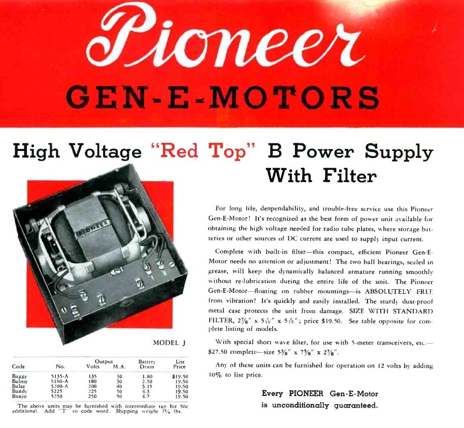
Rotary converters were one practical method for obtaining mobile
HT.
The opposing camp looked at methods of changing the DC into AC so it could be stepped up by a transformer. And so began the Battle of the B eliminator, with each side claiming the superiority of their method.
Why a Vibrator?
A transformer relies on a constantly changing
magnetic flux to induce a voltage in the secondary winding. A transformer
appears as a short circuit to DC, and any attempt to supply it thus will
result in a burn up.
The primary winding must therefore be
fed with alternating current, or a continuously interrupted direct current.
One method to interrupt the current was an electric motor driving a cam
operated switch. Another method was an electric motor with an additional
commutator to provide AC. Such devices were very short lived, being cumbersome
and inefficient.
However, the principles of the electromagnetically actuated vibrating switch had been well known since Victorian times. It appeared in buzzers and bells, but more importantly, in laboratory induction coils. Here, the basic principles were already in use, and it was just a matter of refining them to produce a filtered DC output of a couple of hundred volts, rather than the kilovolt AC output.
Basic Principles.
The basic principles of a vibrator power
supply can be traced back to Faradays famous magnetic ring experiment
from 1831.
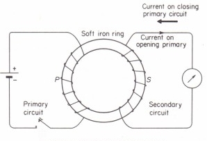
Faradays magnetic ring experiment.
When the switch is closed, current flows
through the primary coil, causing a magnetic flux to build up in the iron
ring. The build up of flux induces a current to flow in the secondary coil,
which registers on the galvanometer. Current stops flowing in the secondary
once the flux has built up to its maximum level. When the switch is opened,
the primary current stops flowing and the flux collapses. In doing so,
this change of flux again creates a current in the secondary coil, but
of opposite polarity. Again, once the flux has reached its minimum, the
current stops flowing.
We can see therefore, that for the secondary
coil to keep producing current, the switch must be repeatedly closed and
opened. Obviously, it is impractical to do this by hand, since it would
become tiresome in a very short time!
What is needed is some kind of automatic
switch. The previously mentioned motor driven switch could be used, but
a vibrating switch along the lines of a bell or buzzer is a more efficient
way of doing the job.
By varying the number of secondary turns
it is possible to produce any voltage we want; the more turns the higher
voltage, and vice versa.
Note that because the current in the secondary
reverses when the switch is opened, the current is thus alternating, and
a rectifier must be included if a DC output is required.
At this point, by replacing the switch with one which continually opens and closes, and providing a much greater number of secondary turns than on the primary, high voltage AC is produced. Once rectified and filtered, we have our source of high voltage DC.
Buzzer.
Next thing to consider is the operation
of a buzzer, and how it might be adapted for our vibrating switch.
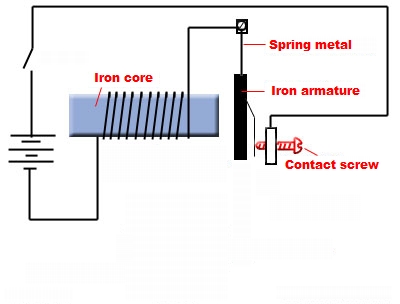
Buzzer provides continuous interrupted current.
At rest, the circuit is completed through
the coil and contacts. When the switch is closed, current flows through
the coil. This causes the iron core to be magnetised, attracting the armature
to it. In doing so, the contact is broken, and the core loses magnetism.
The armature then springs back to its rest position, and the process repeats
so long as supply is maintained. This may be typically a hundred times
a second or more, and is largely dependent on the design of the spring
metal, otherwise known as the reed, and the weight of the armature.
Since the current is interrupted each
time the armature moves towards the core, then if this circuit is connected
in series with the primary winding of a transformer, the current is similarly
interrupted, and continuous alternating current is present across the secondary.
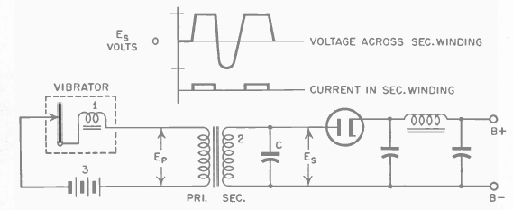
Basic principles of a
vibrator power supply.
Once the secondary voltage is rectified
and filtered, it can be applied to the radio receiver as pure DC.
However, there are many practical considerations
before such a power supply can produce a useful output, free of RF interference,
and for a long time without adjustment.
Induction Coil.
The build up and collapse of magnetic
flux in the core of the buzzer is just like that of a transformer core,
when fed with interrupted current. In the same manner, a secondary winding
can be wound over the buzzers core, dispensing with a separate transformer.
This is the basis of the well known induction coil, which existed in several
forms for laboratory uses, ignition purposes, and for low power spark gap
transmitters.
Model T Ford ignition
coil.
A cheap and readily available induction coil had existed since the advent of the Model T Ford, which used four such coils for ignition. As can be seen in the diagram, it contains the same elements as a buzzer, except for secondary winding on the core, and the presence of a condenser. The latter is necessary to suppress contact sparking.
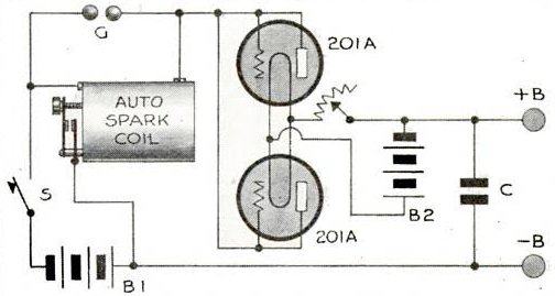
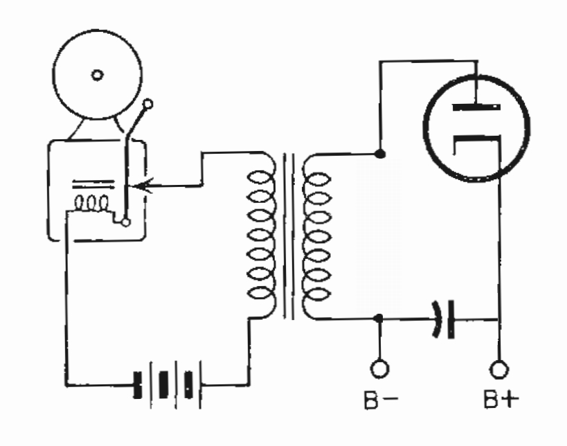
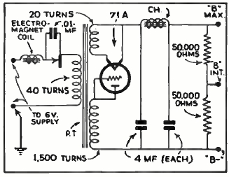
Adaptation of Model T Ford coil supplies B+ voltage.
The device shown above was one attempt at adapting such a coil for the purpose of providing B+ voltage. One may be curious about the seemingly excessive voltage (tens of kV) fed into 201As as rectifiers, but the AC waveform produced is so poorly regulated that the output falls to hundreds of volts under load. The spark gap G absorbs excess voltage under no load conditions. Because there were no indirectly heated valves available, an additional battery is required for the valve filaments. As can be imagined, such a device was hardly practical as a commercially made B battery eliminator!
The Mallory-Elkon B Eliminator.
With car radio becoming popular, serious
attempts were being made for a practical B eliminator.
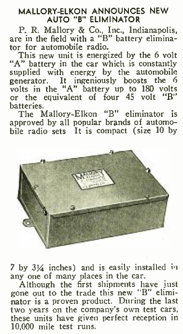
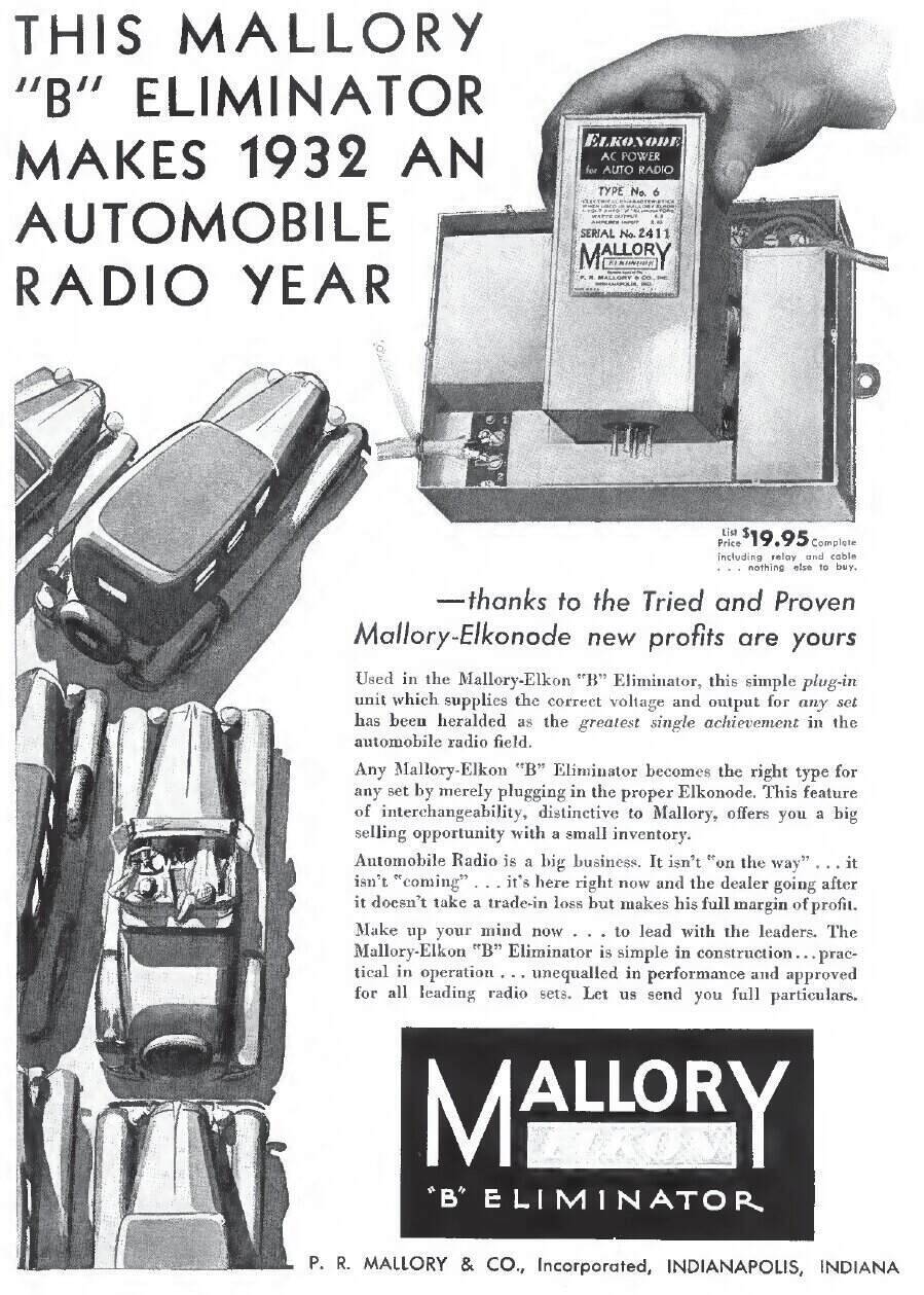
The first commercially
made vibrator power supply.
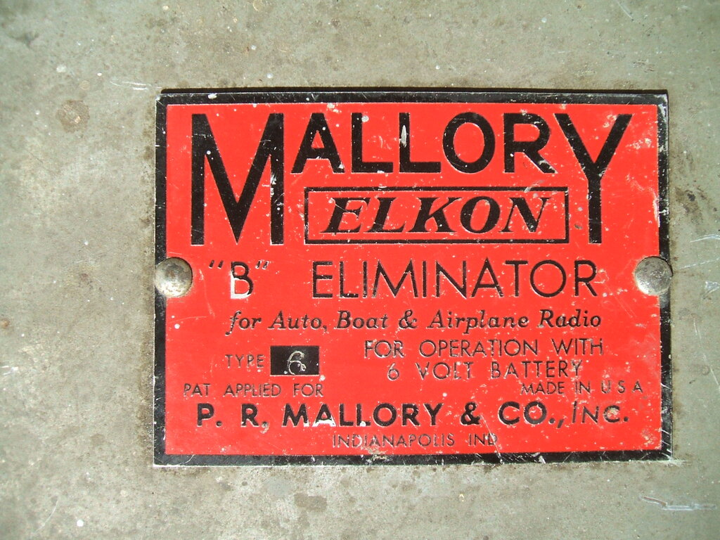
In early 1932, The P.R. Mallory Company released a B eliminator under the Mallory-Elkon name. Since this was the first commercially available vibrator power supply, we will take a closer look at its design.
The name "Elkon" comes from the Elkon Division of the Mallory Company. Philip Rogers Mallory, who founded the company in 1916, initially supplying tungsten for light bulb manufacturers, had, in 1925, taken over the Elkon Company, previously owned by General Electric. The Elkon Division made dry rectifiers and electrolytic capacitors for battery chargers and eliminators. In fact, Mallory was one of the largest component manufacturers in the U.S. Notable achievements were the development of the dry electrolytic capacitor, and the mercury and alkaline batteries, the latter being the company's best known product today, marketed under the Duracell brand.
Types 1 to 6 were the first generation of B eliminator.
Mallory named their vibrating interrupter,
the Elkonode.
Conveniently, their expertise with tungsten
played an important part of the Elkonode development, as this was just
the kind of hard wearing metal needed for its vibrating contacts.
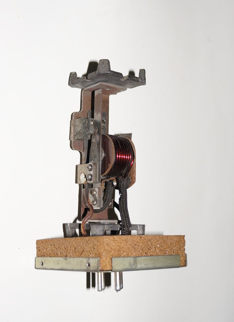
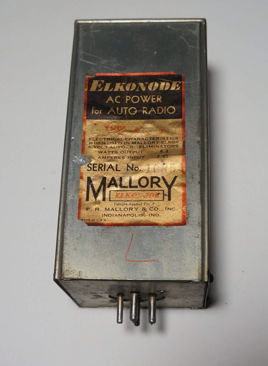
The Mallory Elkonode
the first commercially produced radio vibrator.
The Elkonode is essentially a high power precision buzzer. It is mounted inside a foam rubber lined steel enclosure, for both acoustic and RF isolation to the outside world. It is fitted with a standard UX 4 pin base. Operating frequency of the Elkonode shown was measured at 145 Hz.
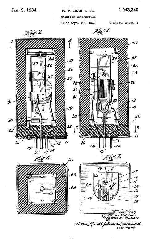
Patent for the Elkonode.
The principle of operation is the same as that of the buzzer in series with a separate transformer, but at a considerably refined level. The Type 6 shown here provides an output of 180 V at 35 mA, and operates from a 6 V battery.
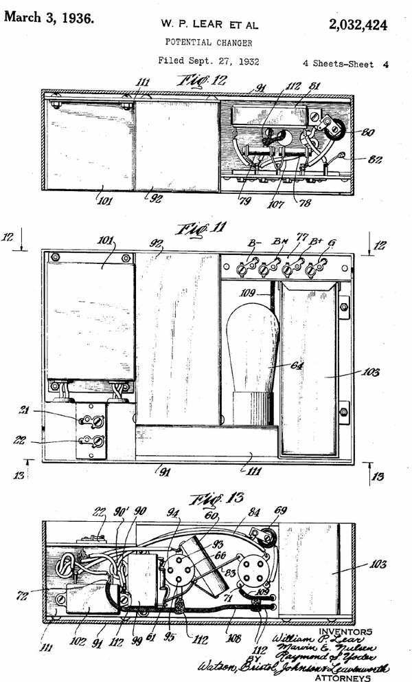
Patent for the Mallory-Elkon eliminator.
At the time of development, the most suitable
rectifier was the gaseous type. Raytheon produced a rectifier especially
for this type of eliminator; the BR. This was a half wave version of the
already extant BH. Indirectly heated rectifiers were two years away, with
the type 84 being released in 1934.
Conventional rectifiers, like the UX280,
were unsuitable because their heater must be at B+ potential, due to the
directly heated cathode. Considering the B+ power output from the Mallory
eliminator was only 6.3 W, the idea of powering such a rectifier heater
(10 W) from the transformer was completely impractical.
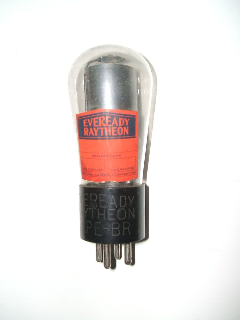
Raytheon BR half wave gaseous rectifier.
A gaseous rectifier operates without a filament. Instead, the valve contains low pressure argon, which ionises when a high enough voltage exists between the cathode and anode. Positive ions of gas bombard the cathode, causing it to heat so that it becomes emissive, and electron flow commences in the usual way.
Operation of the Mallory Eliminator.
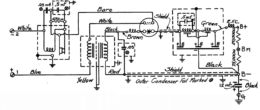
Circuit of Mallory-Elkon Eliminator.
The actual design has additional parts
to make it a practical unit. The Elkonode, or vibrator, has a parallel
RC network across its contacts, consisting of a 450 ohm resistor and 0.5uF
capacitor. This is necessary to reduce contact sparking, as well as to
reduce radio frequency radiation. Similarly, a 0.05uF capacitor across
the whole Elkonode also helps with RFI suppression.
Across the secondary of the transformer
is another 0.05uF capacitor which is known as a buffer or timing capacitor.
Its operation will be explained in a later article, but briefly, it controls
how the magnetic field in the transformer collapses when the contacts open.
Without it, the high voltage created by the transformer back EMF would
soon ruin the vibrator contacts.
The secondary voltage is fed through the
BR rectifier, and into a conventional filter circuit comprising of two
chokes and three 8uF electrolytic capacitors. Across the first choke is
a 0.5uF capacitor, which resonates the choke at the ripple frequency, thus
improving filtering efficiency. There is a voltage divider across the output
which provides an intermediate voltage, where required, for the screen
grids of the receiver.
The 12uF capacitor is a bypass for receivers
where the B- is isolated from earth, because of a back bias circuit.
It will be noted that there are four connections
to the rectifier socket. Two are the anode and cathode, but the other two
are a link inside the rectifier base. This is to prevent the Elkonode functioning
if the rectifier valve is removed, since high peak voltages will otherwise
be developed, causing contact damage.
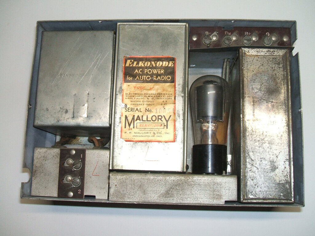
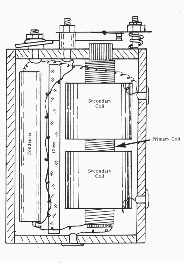
Internal view of Mallory-Elkon Eliminator.
As can be seen from the internal view,
shielding is extensive to prevent interference.
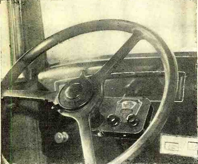
The unit is intended to mount in any convenient
place in the car; typically under a seat, and connects to the cable which
previously went to the B batteries. Supply is to the car battery via a
relay. This is important to minimise voltage drop, which would otherwise
occur through the normal set wiring and switch. The relay coil was intended
to be connected to the receivers dial lamp or speaker field coil.
B batteries for car radios were now obsolete.
The Mallory Elkonode was most commonly
used in the type of eliminator shown, but as it was realised that B batteries
were becoming a thing of the past, a few manufacturers began to build the
Elkonode, transformer, BR rectifier, and other components into the set.
Motorola (Galvin Mfg. Co.) was the first
to do so, with their models 61 and 88. The Elkonode fitted to these sets
had only a two pin base, with the suppression components mounted internally.
Details of these early Motorola sets can be seen at https://www.worldradiohistory.com/Archive-Rider/33/Rider-1933-GHI.pdf
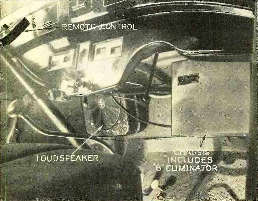
Motorola 88 installation.
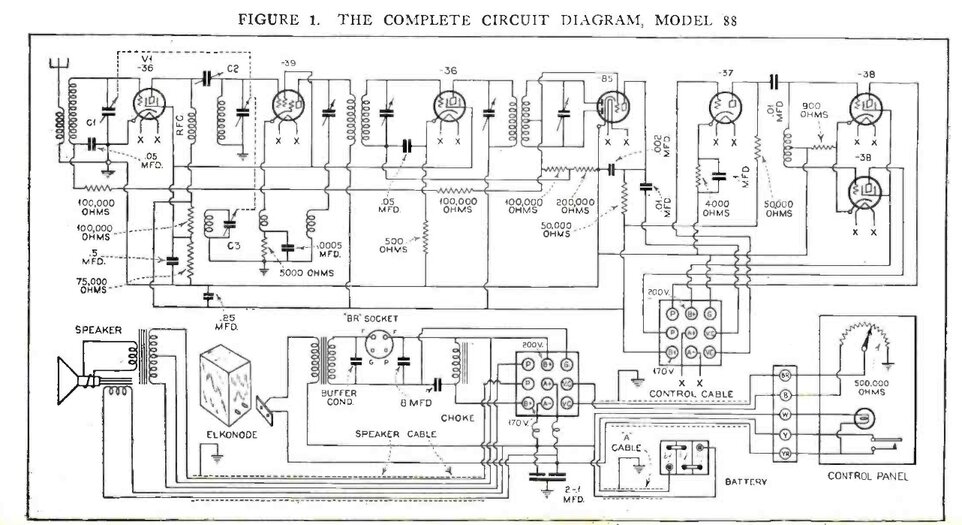
Circuit of the Motorola 88.
As a collector of vibrator power supplies, the Mallory Elkon eliminator was not surprisingly, at the top of my wish list. It was a patient wait for quite a few years before one turned up on eBay. This model was only produced for about a year, and it must also be remembered that car radio was still in its infancy, so these first generation eliminators are comparatively rare. You can see the restoration details here https://www.cool386.com/mallory_elkon/mallory_elkon.html
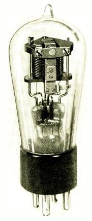
The B Tube.
This curious looking novelty, described
in Radio Craft for August 1932 https://www.worldradiohistory.com/Archive-Radio-Craft/1930s/Radio-Craft-1932-08.pdf,
was another variation of the vibrator theme.
A vibrator was mounted inside an evacuated
glass tube, just like an ordinary radio valve. This was done in an attempt
to stop the contacts oxidising from sparking, which was a problem with
some designs at this stage of the technology.
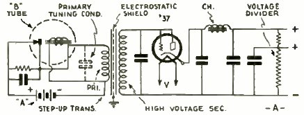
Eliminator using the B Tube.
The 37 valve used for the rectifier was
specially made for this purpose, since it had mercury introduced, to reduce
voltage drop. It is not clear if this device was ever put into production.
It can be imagined that this method of vibrator construction would be more
expensive, and looking at the weighty mechanism supported only by the glass
pinch, would appear rather fragile for automotive use.
It is interesting to note however, that
the idea of a gas-tight vibrator was revived later on during World War
2. With aircraft flying at high altitudes, vibrators were filled with nitrogen
to prevent contact arcing, which otherwise becomes problematic at low air
pressure.
Home Made Eliminators.
Of course, the home constructor and experimenter
had a go at making their own vibrator power supply.
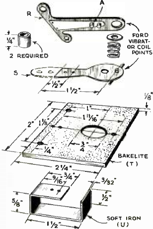
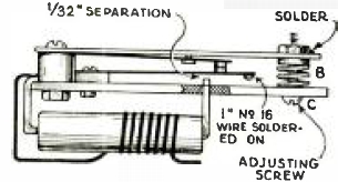
Home made eliminator using Ford coil points.
This design from Radio Craft, November 1934, https://www.worldradiohistory.com/Archive-Radio-Craft/1930s/Radio-Craft-1934-11.pdf described an eliminator using points from a Model T Ford coil, and a home made transformer. The rectifier was a 71A triode, with its heater supplied from the transformer. The 0.01uF across the coil points is completely insufficient for spark suppression, especially as there is no buffer capacitor across the transformer.
Another design for home construction used a complete Model T Ford coil, but with a separate transformer. The following was described in the Radio Builders Manual for 1935:
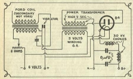
Ford coil drives a separate transformer.
Only the primary winding of the Model T
Ford coil is used, which excites the vibrator. A separate transformer steps
up the voltage. This is preferable because of the more suitable turns ratio.
Additionally, full wave rectification provides some improvement to efficiency,
even though the half wave vibrator produces an asymmetrical waveform. By
this time, the 84 full wave indirectly heated rectifier had become available.
A brief experiment with this design showed
some promise, but it would at least need proper RFI suppression to make
it usable for receiver use.
It must be remembered that these home
made eliminators cannot be expected to perform as well as the commercially
made version. Oddment transformers, randomly adjusted ignition points,
and spark suppression capacitors selected by guesswork, will not give particularly
long contact life.
Half Wave Operation.
Eliminators, such as the Mallory Elkon,
were what the industry needed, because car radio could only become popular
once the problem of providing the high tension was solved. While the Mallory
Elkon eliminator was successful, it still had limitations.
Since the transformer was fed with pulsating
DC, rather than true AC, the core was subject to magnetisation, which not
only reduced efficiency, but required a core larger than otherwise necessary.
Importantly, the half wave operation limited power output, and some car
radios used class B output stages to make best use of the limited HT.
It will be noted that the all the transformer
primary current flows through the vibrator driving coil. If the load current
changed, the magnetic pull is also changed, which affects the operating
characteristics of the vibrator. This in turn affects tuning of the circuit,
and results in sparking. For a given design of eliminator, the load current
has to be kept within narrow limits. The work around for this was to provide
different Elkonodes, to suit a range of output currents.
At the time, just as many cars were negative earth as positive earth, so this had to be taken into account. If the supply polarity is reversed, the rectifier conducts on the transformer back EMF, rather than during the portion of the cycle when the vibrator contacts close. The result is a poorly regulated low output. This could also damage the vibrator, because the loading is much less during this part of the cycle. It was therefore necessary to provide for operation on either input polarity. This could be done by reversing the connections to the transformer, or in the case of the Mallory eliminator, by floating the entire primary circuit above earth.
Despite these limitations, the Mallory eliminator was popular, and provided reasonably good performance and life from the vibrator. By mid 1932, Utah Radio Products also released a very similar eliminator to that of Mallory. In fact, it used the same Elkonode.
From here on, development was rapid, with considerable improvement in performance and reliability, as the science began to be properly understood. In the next article, we will look at the improvements to vibrator power supply technology, and how it became firmly established, not just for mobile radio use, but for domestic sets, and independent AC power supplies.