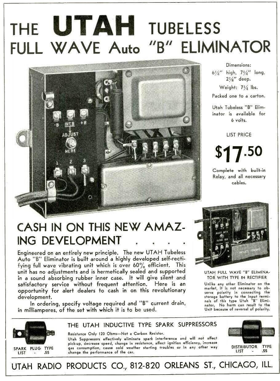
Utah had achieved full wave operation by 1933.
Utah had achieved full wave operation by 1933.
Synchronous Rectification.
Following on from the Mallory-Elkon Type
1 to 6 eliminators described in Part One, the next stage of development
was synchronous rectification.
In 1933, Mallory released the Type 10
to 14 eliminators with a Self Rectifying Elkonode. This would become
known as a synchronous vibrator.
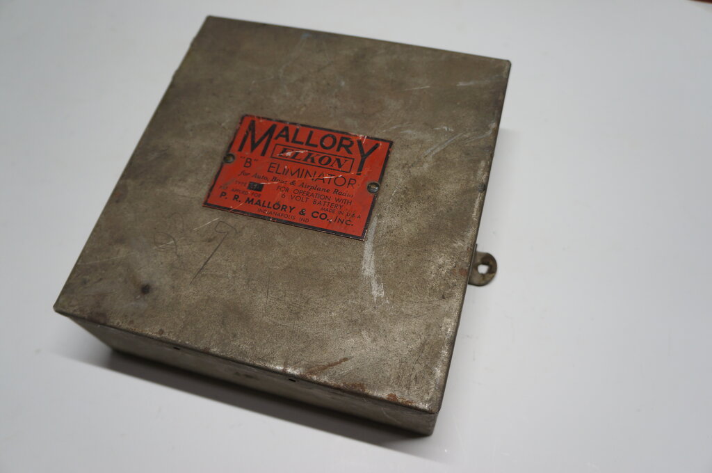
Mallory-Elkon Type 11 eliminator.
Along with the primary (interrupter) contacts,
a second set of contacts are included which perform rectification.
Valve rectifiers lose efficiency due to
the voltage drop between anode and cathode. Except for gaseous types, current
is also required for the heater (typically 600 mA). If the rectifier valve
can be eliminated, the power supply becomes more compact and efficient.
At this point, the rectifier can be thought
of as a switch, which is on only when the transformer secondary goes
positive. It was soon realised that an additional reed, with another set
of contacts, could be fitted to the vibrator to do exactly this.
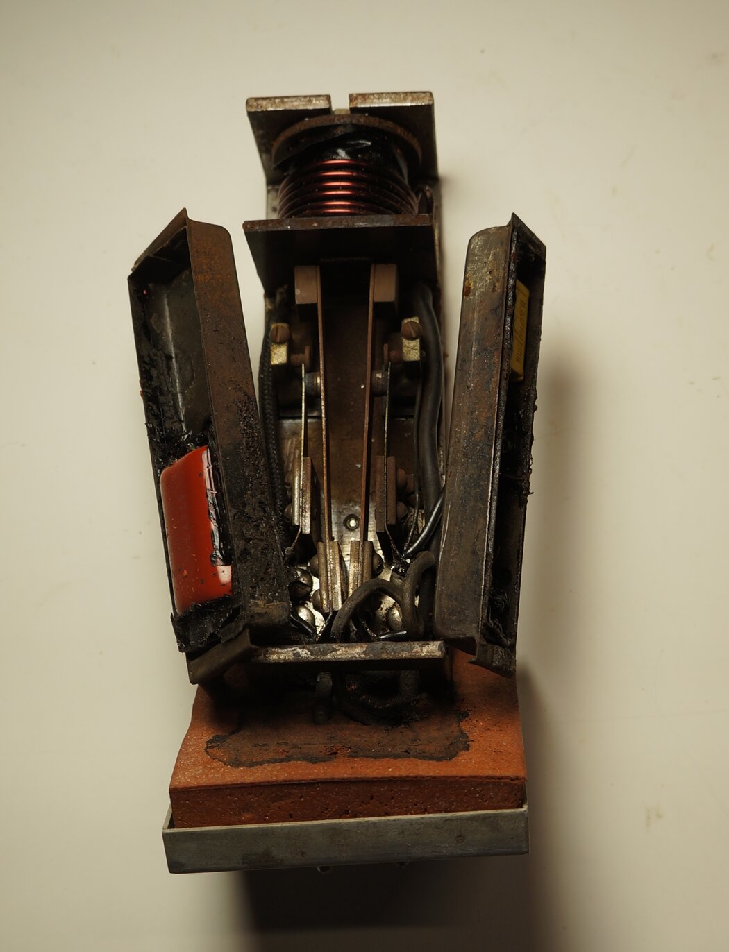
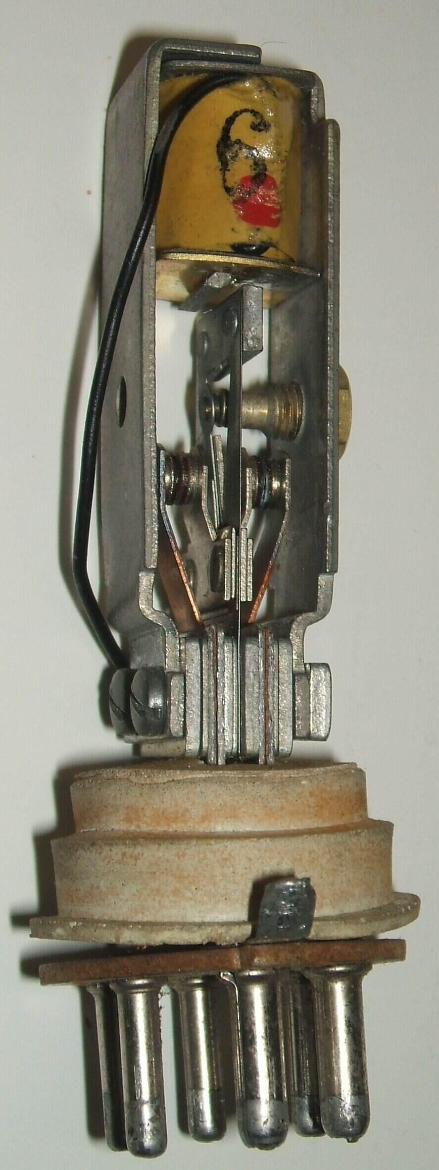
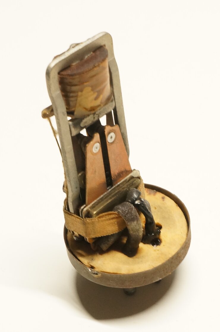
Internal parts of the Self Rectifying Elkonode. Note the second
reed.
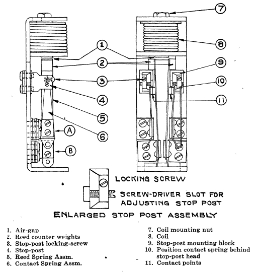
The two sets of contacts must vibrate in synchronism for this scheme to work, and thus the two reeds must be identically matched.
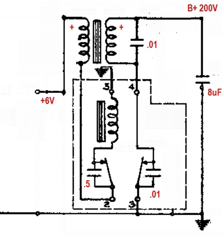
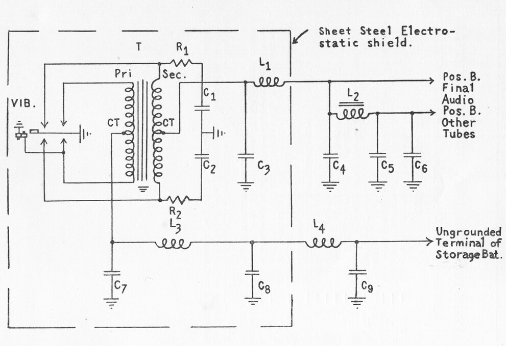
Simplified circuit of the Self Rectifying Elkonode.
Consider the circuit above when 6 V is
first applied. Current flows through the transformer primary, contacts,
and drive coil. Transformer action causes current flow in the secondary
winding, charging the 8uF filter condenser via the rectifier contacts,
which are also normally closed. The windings are phased so that the 8uF
charges positive with respect to earth.
The current flowing through the drive
coil magnetises its core, pulling the contacts towards it, thus opening
the primary circuit. The magnetic field in the transformer primary collapses
and the polarity of the secondary voltage reverses. This would discharge
the 8uF, except that now the rectifier contacts have also opened, disconnecting
the transformer secondary, and the capacitor remains charged.
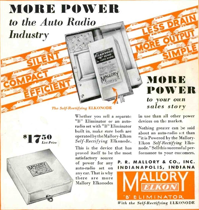
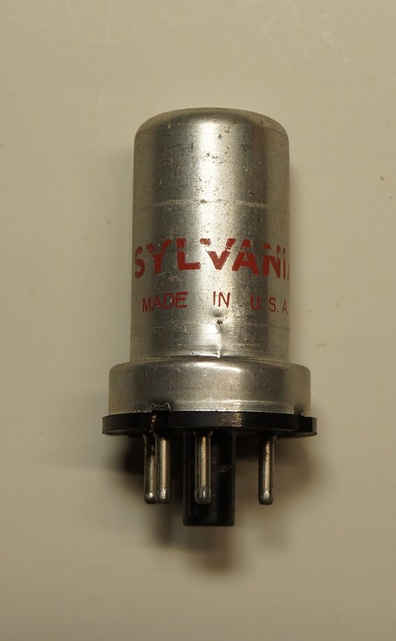
New eliminator is smaller
than the previous valve rectifier type.
The Self Rectifying Elkonode worked well, but still had the limitation of half wave operation, and the load current affecting vibrator operation. In this instance, certain load conditions could cause the primary and secondary reeds to vibrate out of sync, causing arcing at the contacts. Details of the type 11 eliminator can be seen at https://www.cool386.com/mallory_elkon_11/mallory_elkon_11.html
The Modern Vibrator.
1933-34 brought a significant change to
the technology, solving all these limitations. Firstly, one common reed
ensured the primary and secondary contacts were always in sync. Full wave
operation was implemented, and the driving arrangements were altered to
be independent of load.
Besides Mallory, other manufacturers including
Utah, Oak, Radiart, and Electronic Laboratories, entered the scene, each
contributing to the technology.
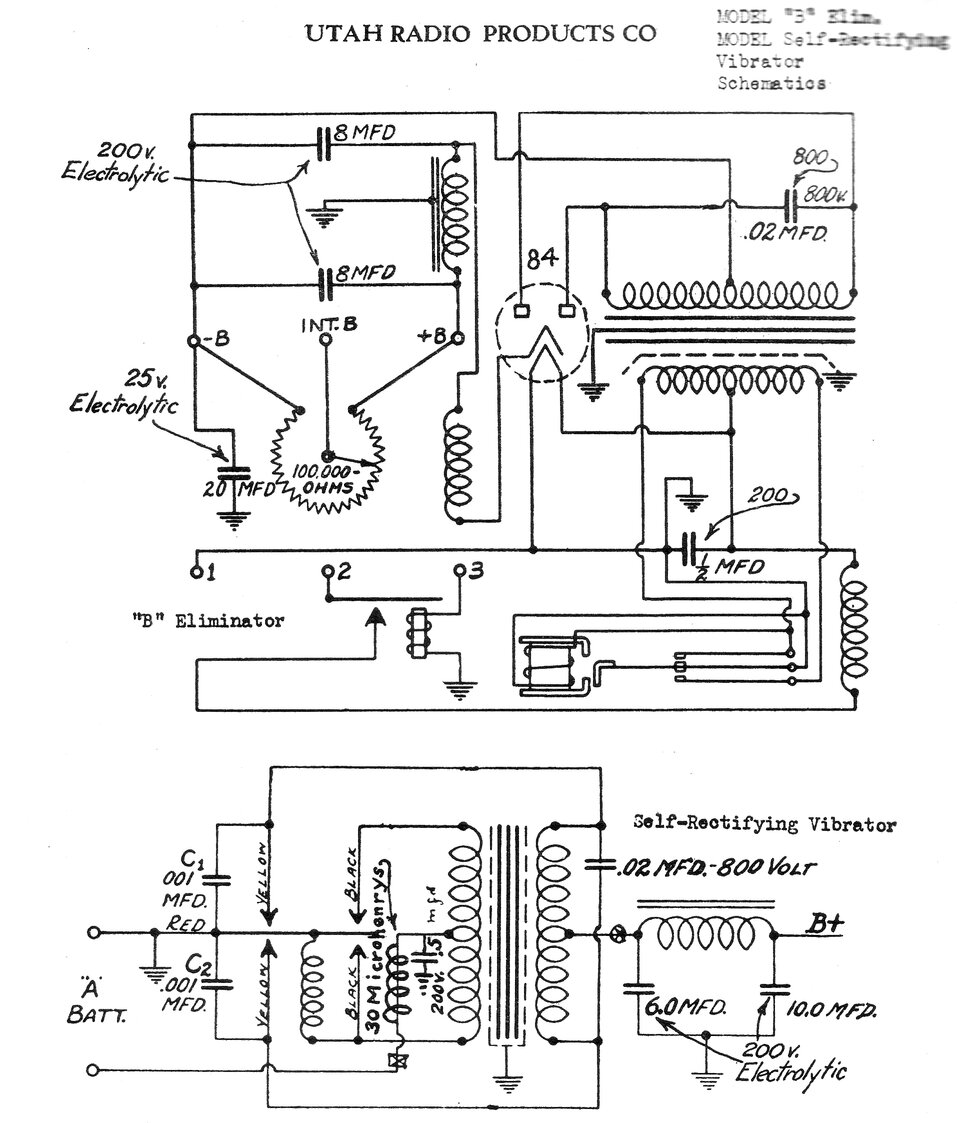
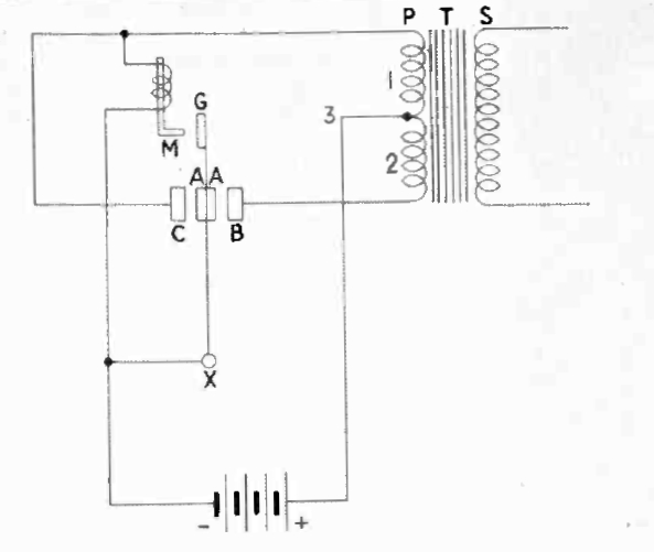
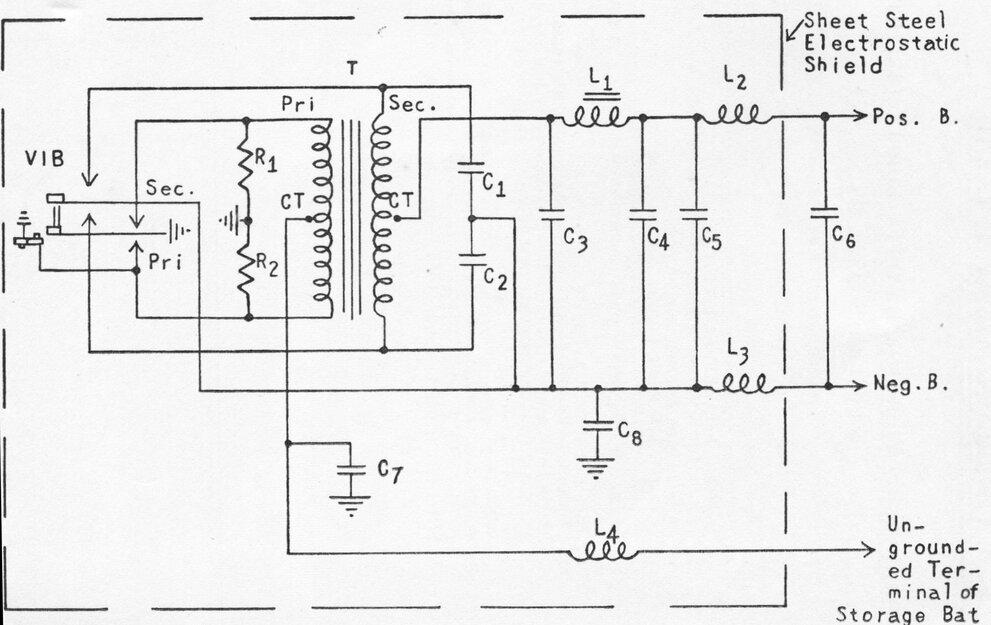
Circuit of the Utah full wave eliminators.
Utah was the first with the full wave and
shunt drive vibrator. Since this is the basis of the modern design, we
will have a closer look at how it works. Ignoring the coil drive arrangements
for now, let us first examine full wave operation.
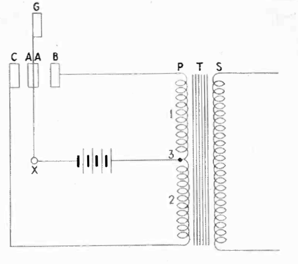
Simplified full wave circuit.
The reed (G) has contacts (A) on both sides. When the reed swings to the left, contacts A and C make, causing current to flow in the lower half of the primary (2), causing a build up of magnetic flux in the transformer core (T). When the reed swings to the right, making connection between A and B, the upper half of the primary (1) is similarly energised, but the winding direction is such that the current, and thus the flux, flows in the opposite direction. The transformer now functions as if it has proper alternating current applied, and the secondary can be full wave rectified to provide DC. This circuit is more efficient, because the transformer is now fed with current on both sides of the reed swing, and core magnetisation is avoided. In short, a greater output is available with a smaller transformer. The next improvement was to make the reed vibration independent of load current.
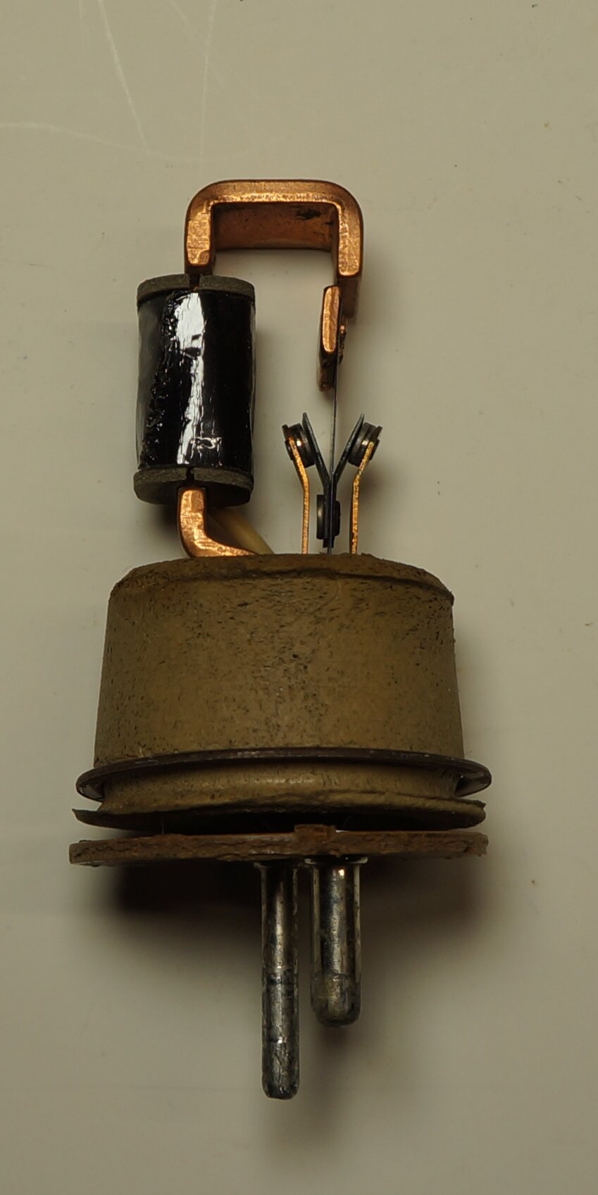
Shunt drive vibrator. Cornell Dubilier C-3 shown.
The drive coil wound on its iron core (M), is now connected between contacts A and C. Instead of a few turns of heavy gauge wire, the coil now has many turns and presents a much higher resistance; typically a few hundred ohms. When the battery is connected, current flows through section 1 of the primary, through the driving coil and back to the battery. The reed (G) swings over to the drive coil (M), causing contacts A and C to make, as before. However, in so doing, the driving coil is now short circuited. With no magnetic attraction, the reed swings back, past its original centre position because of inertia, causing contacts A and B to make. Since the coil is no longer shorted, the process repeats. This method of coil operation is called shunt drive, because the coil is across the supply, rather than in series with it. As such, loading of the transformer has minimal effect on reed vibration. Note that because of transformer action, the drive coil is actually supplied with about twice the battery voltage. A variation of the shunt drive method operates the drive coil completely independently of the transformer and its switching contacts.
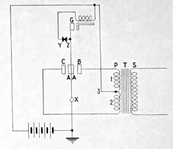
Separate drive vibrator. Oak V4012 shown.
Another set of contacts are provided; Y and Z which are normally closed. When the battery is first connected, current flows through the coil, and contacts Y and Z. As before, the reed weight (G) is attracted to the coil. Contacts A and B make. Additionally, Y and Z are now open circuited, so the coil loses magnetism, and the reed swings back causing A and C to make. Contact is again established between Y and Z and the process repeats. This method is called separate drive but is also often called series drive, despite this term originating from the older Elkonode type of design.
Both shunt and separate drive designs remained
standard until the end of vibrator technology. The shunt drive type is
easier to make and adjust, but the drive coil operation is dependent on
the condition of the power contacts. For this type of vibrator to give
long life, the contacts must be of especially good design, because if the
contact spacing increases, starting becomes difficult.
The separate drive type is more complex,
but more reliable. Drive coil contact wear is largely a non issue because
of the low current (a couple of hundred mA). No matter how worn or dirty
the power contacts are, the reed will always vibrate normally. With this
type of vibrator, imperfect contact condition simply means reduced output,
rather than being completely inoperative.
One of the earliest separate drive (and
synchronous) vibrators was the RCA 7604 from 1933. This was described in
Radio Waves, January 2020. It was used locally by AWA for their R74 car
radio in 1934 (Radio Waves, July 2019).
RCA 7604 vibrator installed in the AWA R74 power supply.
Dual Interrupter Vibrators.
Further to the Synchronous and Non-Synchronous
types, brief mention needs to be made of the Dual Interrupter type. Where
the contact ratings of an ordinary vibrator are insufficient, an extra
set of contacts are provided in the same way as a synchronous type. These
can be paralleled to increase the permissible primary current, or preferably,
by providing the transformer with two primaries; each switched by the individual
contact sets. The latter provides better current sharing between the two
contact sets, since it is impossible to ensure each contact pair makes
and breaks at exactly the same time, every time. This type of vibrator
is used for applications such as transmitters, high power audio amplifiers,
and 240V AC inverters.
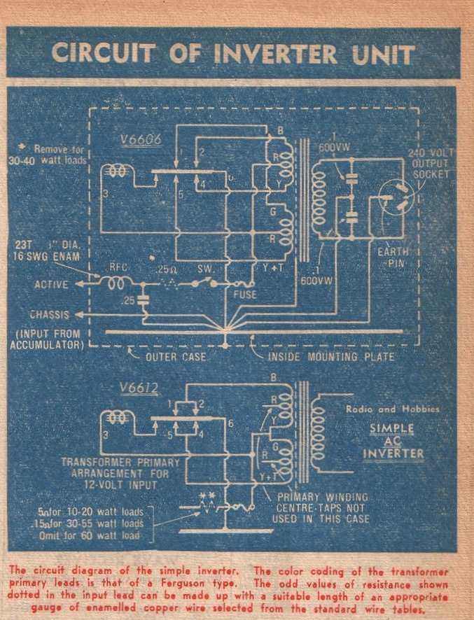
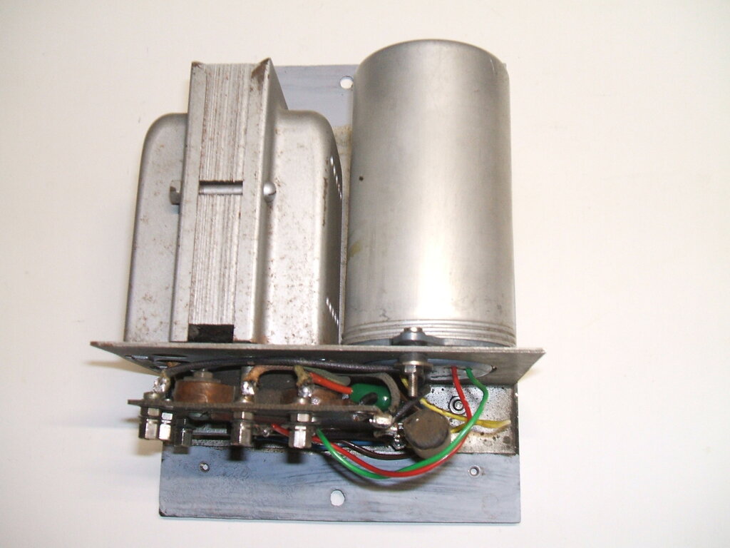
Dual Interrupter Vibrator used in 240V Inverter.
Efficiency.
By 1935, the required performance and
reliability had been achieved by the vibrator. Further improvements continued,
resulting in smaller and quieter vibrators with longer life.
Despite comments often made to the contrary,
vibrators are actually a very efficient method of power conversion. Apart
from the small amount of power required for the driving coil, most of the
losses occur in the transformer. Since the switching is done by physical
contacts, voltage drop is minimal. In fact, the contact resistance is comparable
to a modern MOSFET, with a typical on resistance of 50 milliohms. Efficiency
of a well designed full wave vibrator power supply can exceed 80%.
The motor-generator could not compete
with this, along with the compactness, quietness, and lower cost of the
vibrator. The vibrator had won the Battle of the B Eliminator.

Mallory was the worlds largest vibrator manufacturer, with 80%
of the U.S. market.
Rectification.
Where a vibrator switches only the primary
winding, it is called a non-synchronous or interrupter type. DC output
is provided by a rectifier and capacitor input filter. Half wave rectification
is undesirable with full wave vibrators, since apart from lost efficiency,
wear will be accelerated on one set of contacts. Choke input filters affect
the operation of the timing circuit, and also reduce contact life. An example
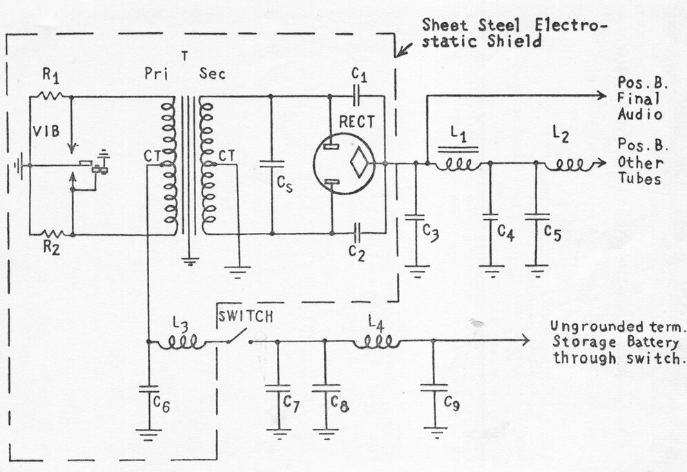
of a valve rectifier circuit is shown below:
AWA 946-AZ car radio power
supply with valve rectifier.
As can be seen, rectification and filtering
is the same as with any other transformer type power supply.
The first full wave indirectly heated
thermionic rectifier was the 84, later known as 6Z4. This valve was specifically
developed for car radio use, and was released in early 1933. It developed
into the octal 6X5, and later, the miniature 6X4.
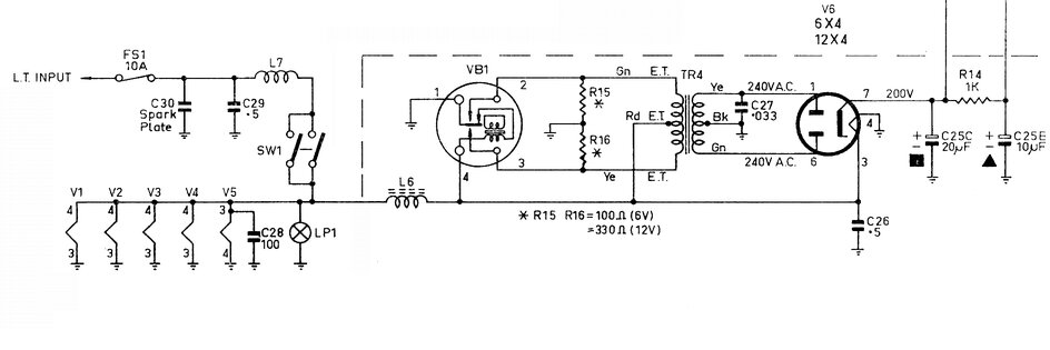
The gaseous rectifier returned again in
1935, in the form of the 0Z4, and was popular in the U.S.
Power supply with 0Z4 rectifier.
The OZ4 can generate RFI, hence the inclusion
of C1 and C2. Otherwise, it is used in the same way as other rectifiers,
except for no heater connection. The 0Z4 was not made in Australia, and
few local sets used it. Selenium and silicon rectifiers have also been
used in their usual configurations.
Note that the supply polarity is unimportant
for full wave non-synchronous vibrators, except in a few cases where ancillary
circuits are designed otherwise. This is because the transformer primary
sees the same AC no matter which way the supply is connected. The other
method of rectification is of course the synchronous type.
Synchronous full wave vibrator circuit and Ferrocart PM104.
The primary circuit works in the usual
way, using the right hand set of contacts. Rectification is carried out
by the left hand (secondary) set. One way to understand operation is to
consider the secondary contacts as diodes, with the cathodes connected
to the secondary winding, and the anodes to earth. The circuit then becomes
a conventional full wave centre tap type, but with the centre tap being
positive with respect to earth. Since the diodes switch in synchronism
with the primary contacts, we can see that output polarity remains constant.
Because the reed is common to both the
primary and secondary contacts, and is earthed, it is not possible to generate
any negative voltage by means of a back bias circuit. The split reed
vibrator solves this problem. The reed is divided in half, with the primary
and secondary contacts electrically isolated from each other, but mechanically
coupled by an insulator. The negative side of the output is no longer tied
to earth.
Split reed vibrator allows
negative output to be isolated from earth.
Car radios mostly use non-synchronous vibrators,
to enable the set to work with both positive and negative earth systems
without modification. The additional rectifier heater current was seen
as trivial for a car electrical system. Where synchronous vibrators were
used, both supply polarities had to be catered for. One method was to reverse
the transformer primary wires by means of a terminal strip. The most elegant
scheme was a reversible vibrator base, patented by Mallory. The vibrator
was simply withdrawn, rotated 180 degrees, and plugged back in. The secondary
contact connections are then reversed, but the primary connections remain
as before, since their connections are crossed over in the socket. This
type of base was not used with Australian made vibrators.
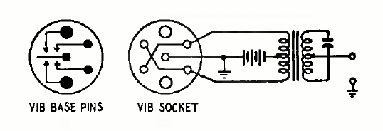
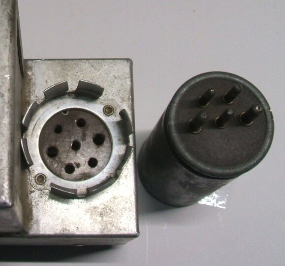
Reversible base for synchronous vibrator.