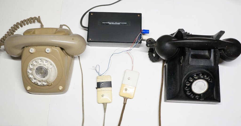
No need for a complicated exchange when only two phones are required.
Use your automatic telephones as an intercom with this simple circuit.
No need for a complicated exchange when only two phones are required.
With the prevalence of automatic (dial)
telephones now left over because: 1) mobile phones have virtually ended
land lines, and, 2) many commercial services require tone dialling, the
question arises, what can you now do with them?
They can in fact still be used as a landline
phone on the internet via a VOIP service. In Australia, that means using
the NBN (National Broadband Network). The NBN modem has a telephone connection
which is activated if you have a home phone plan with your ISP. Since tone
dialling is required with most modems (and to make the phone practical
to use), a Dialgizmo is required to convert the dial pulses to tones.
Home Telephone Exchange.
If you don't wish to use them as a land
line to the outside world, it's possible to set up a domestic exchange
which allows nine phones to call each other.
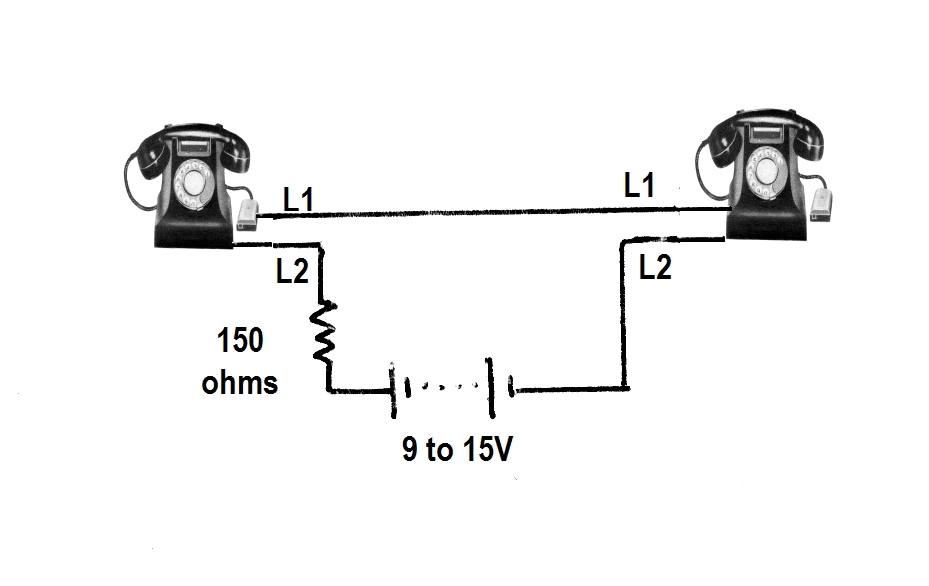
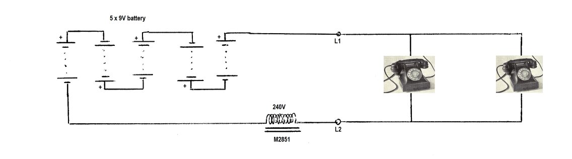
Simple series connection operates the speech circuit, but does not
provide for signalling.
L1 and L2 are the two line connection designations to each phone. Sometimes they are designated as A and B, or L+ and L-.
The method of connection is quite different
to that used with a conventional exchange, but need not concern us here.
When both phones are off hook, about 25mA flows through each phone. The
speech circuitry operates normally, and a conversation can take place between
the two. The limitation is that no signalling is possible between the phones.
The 150 ohm resistor is for current limiting. If, for some reason, the
dials of both phones should be operated at the same time, the power supply
would be short circuited. There is the possibility of damaging the phones
and/or power supply.
In practice this is unlikely to happen,
since operating the dials does not achieve anything with this circuit.
Provided there is no risk of both dials being used simultaneously, the
circuit can be further simplified by removing the 150 ohm resistor. In
this instance, the supply voltage should be 6 to 9V. The resistor is not
required with central battery phones, since there is no dial to short circuit
the supply.
Dry cell batteries are ideal for the circuit,
since they provide hum free operation, and will last their shelf life with
the low current drain. (Best not to use alkaline cells for the long term,
because they're likely to leak - use carbon zinc or lithium instead). Plugpack
eliminators can also be used, provided the output is well filtered. If
experimenting with different power supplies, the current should not be
allowed to exceed about 50mA.
Both automatic or central battery telephones can be used with this circuit. Since it lacks signalling facilities, it has no practical application beyond proving the concept or providing amusement.
Signalling.
Most simple telephone intercom circuits
which have been published over the years use something like the above circuit.
They get around the signalling problem by adding a buzzer and push button
switch to each phone, with the buzzer operating off the low voltage DC
supply. This is a crude solution because; 1) the dial and bell never
do anything, 2) the DC buzzer and push button switch are foreign
objects which detract from the originality of the phone, especially if
holes are drilled to accommodate them, 3) the calling sounds completely
out of place coming from an electronic buzzer, 4) extra conductors
are required between the phones.
However, there is a very simple way to use the phones in their original entirety with functioning bells and dials! And a two wire cable!
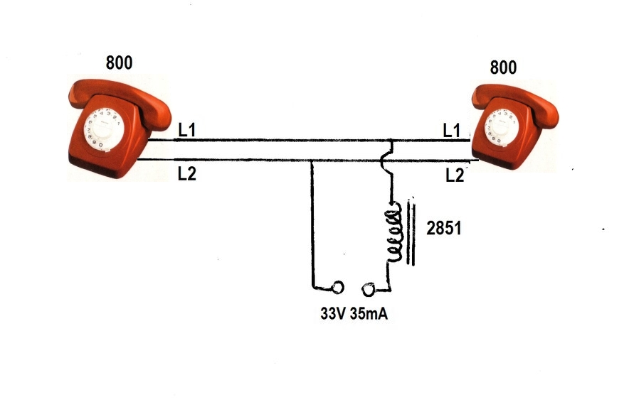
Speech Circuit.
The two telephones are simply connected
in parallel together. They are then connected to a 33V DC power supply
through an audio choke. The choke provides three functions: 1) its
DC resistance limits the current to each phone, 2) the inductance
isolates the speech signal from the power supply, and 3) the back
EMF generated by the inductance during dialling increases the 'ring' voltage
to about 45V. The choke used here is the 240V winding of a 2851 power transformer.
This has a DC resistance of 930 ohms, which limits the short circuit current
to 35mA.
If one phone is taken off hook, about 30mA of current will flow through the choke and the phone. This is slightly less than the short circuit current because of the voltage drop across the phone. AC voltage corresponding to speech will be present across the choke (roughly about 1V), and the line to the other phone. Now, if the second phone is taken off hook, its speech circuit is connected directly to that of the first phone. Speech from the first phone will thus be heard in its receiver. The DC supply current will also be divided between the two phones.
A limitation of this arrangement is that one phone might draw most of the DC current, leaving not enough for the other. Lack of current results in poor transmission. In a 'proper' design, each phone would have its own choke, and the speech circuits would be coupled via a capacitor. This way each phone gets its optimum current without upsetting that of the other. Therefore, the phones used with this circuit should be of the same general type.
Dialling and Ringing Circuit.
Some of you may remember back to the days
when the 300/400/800 series phones were to be seen in every house, and
occasionally may have heard bell tinkling coming from another phone when
someone was dialling out. More than likely, the 'extra' phone had not been
legally installed by the PMG/Telecom. Because, if it had, you wouldn't
have heard the tinkling. The reason being, most such installations were
not done correctly. The extra phone was simply paralleled across the line.
As far as the dialling and speech circuits were concerned, everything worked
normally. However, the problem was that with this two wire connection,
the line being shorted and opened on each dial pulse would cause the bell
capacitor in the other phone to charge and discharge. Since the charging
current flows through the bell, the bell responds by tinkling. The correct
way to have done the installation is with a three wire connection, where
the bell circuitry is isolated from the speech/dialling circuit. More details
on this is covered here.
This 'incorrect' connection is deliberately used in the ETI-291 for the purpose of bell ringing. First, let us examine the dialling circuit:
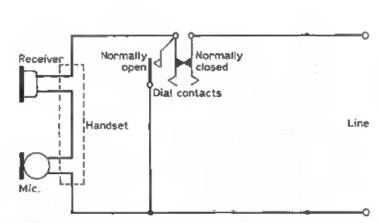
Simplified dialling circuit.
On the back of the dial there are two sets of contacts. The normally open contacts are open at rest, but close as soon as the dial is rotated. They remain closed, in both directions of travel, until the dial returns to the rest position. Their function is to short circuit the speech circuit, since loud clicks would otherwise heard in the receiver during dialling. The speech circuit also needs to be taken out of circuit to eliminate its voltage drop, and the possibility of causing dialling impulse distortion.
The normally closed contacts operate as the dial returns anti-clockwise from the finger stop, opening as the dial passes each digit, until it returns to the finger stop. From this, we can see that when a telephone is dialled, the line is short circuited, and then open circuited a number of times corresponding to the of the digit dialled. The dial return speed is ten pulses per second.
It should now be clear why an automatic
telephone should never be connected directly to a battery or other power
supply, without any current limiting.
Having learned how the dialling works,
the next thing is to examine how this intercom circuit actuates the bells
in the other phone.
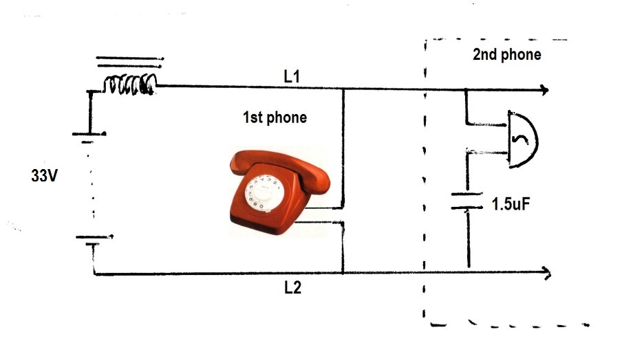
Basic bell ringing circuit.
Looking at the above diagram, we can see the 1.5uF bell capacitor in the second phone is charged to 33V via the the audio choke, and the coil of the bell.
When the dial of the first phone is taken around to the finger stop, the short circuit between L1 and L2 causes the charged capacitor to be connected directly across the bell, causing it to strike the gongs. When the dial is let go, the connection between L1 and L2 is now open for a brief moment. The 33V supply now charges up the capacitor again. Since this charging current flows through the bell, it strikes the gongs again. This opening and short circuiting of the line occurs as many times as the digit dialled.
Suitable Phones.The ETI Design.
The simple circuit shown previously is
perfectly practical to use as is. Indeed, it was used for testing this
design. However, the ETI-291 also included the circuit for a power supply.
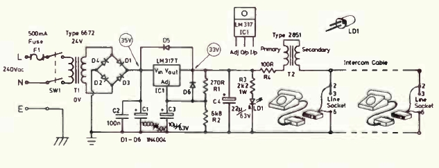
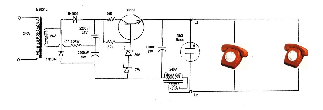
Circuit of the ETI-291.
It could be argued the design of the power
supply was overkill. Firstly, the 6672 mains transformer was vastly bigger
and more expensive than needed, seeing that only about 35mA is required
- or 50mA with the power LED. The 6672 is rated at 1A. As it was, the Jaycar
kit cost $59.95, and this could have been reduced considerably with a smaller
transformer (for example, the Altronics M2854L which provides 24V at 150mA).
The supply did not need the complexity
of the regulator, although it is true that it guarantees a hum free speech
circuit. There isn't much headroom for the regulator as shown, but to increase
the voltage at the input would risk exceeding its rating, without redesigning
the circuit.
The choke was actually a 2851 power transformer.
For those outside Australia/NZ, the 2851 is a very common 240V to 12.6V
CT 150mA transformer. It has been a standard, particularly for magazine
projects, since the late 1960's, and was originally produced by Ferguson
under the PF-2851 part number. As can be seen, the primary is connected
in series with the secondary to obtain more inductance. Obviously, the
windings must be phased correctly. It is not essential to use the secondary
this way, since it has only 1/20th the number of turns as the primary.
This was confirmed in practice. Inductance of the 240V winding of the tested
transformer was 8H.
R4 is a 100 ohm resistor in series with
the choke. Its inclusion is unnecessary, since the 2851 primary already
has 930 ohms of DC resistance (on the measured example).
Of course, a commercially made supply
could be used instead, to reduce the amount of work building the unit.
For example, early HP Deskjet printers used an outboard 30V DC power supply,
which would be ideal for this.
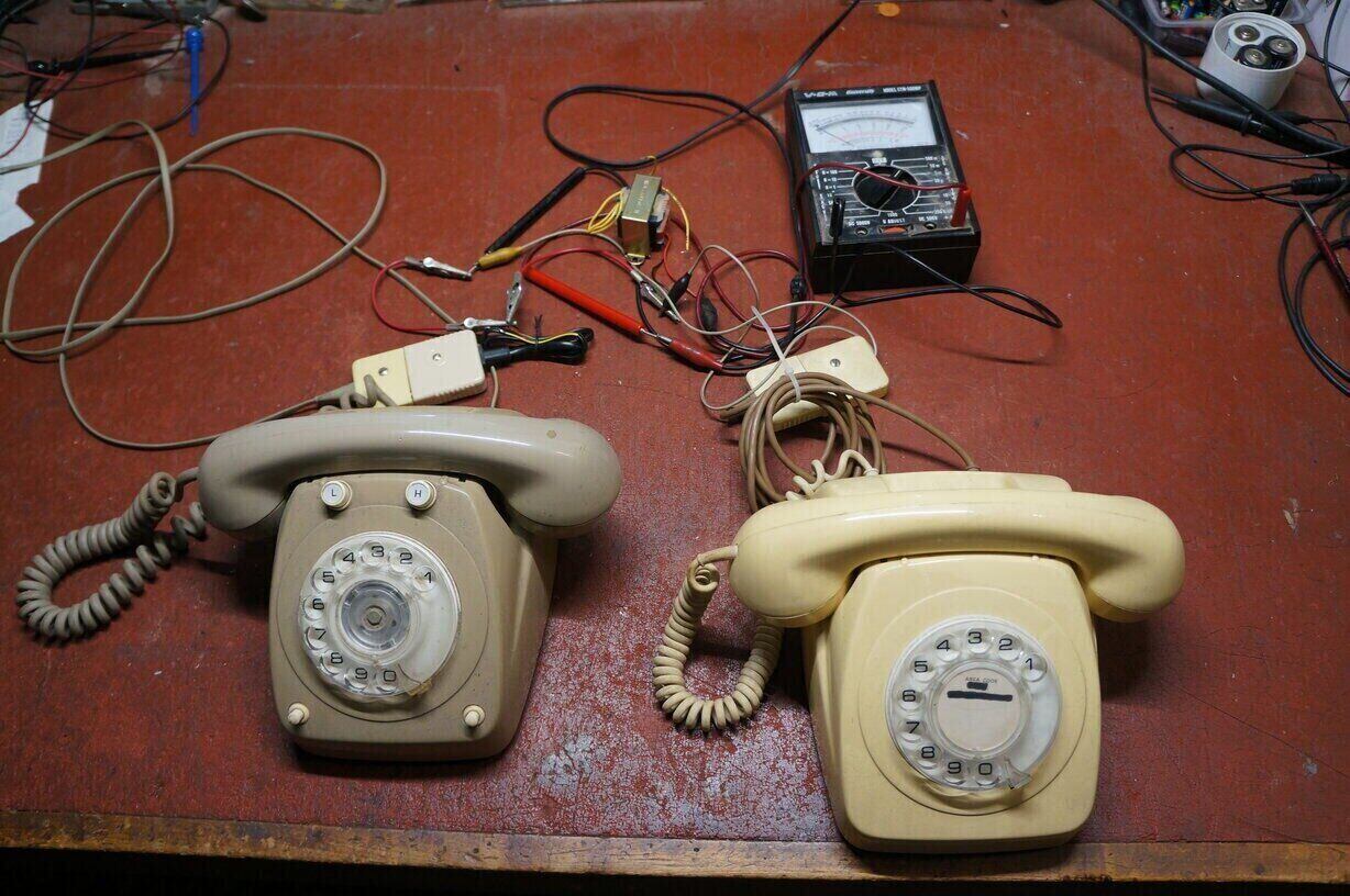
Testing the concept of the ETI-291.
Performance.
How good is it? With a 33V supply, it
certainly works well with series 800 phones as specified. However, it was
found that when other types of phone were tried, the ringing was not always
acceptable.
Presumably, this is because the series
800 bells are more sensitive. We cannot be critical of the design, since
it was specified for series 800 phones. Nevertheless, it was only a simple
matter of increasing the supply voltage to allow other phones to work.
On that note, the original push-button series 800 phone does require a
higher supply voltage.
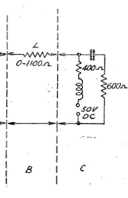
C is the equivalent exchange circuit. 400 ohms is the DC resistance
of the retard coils. B is the subscriber line, with the resistance L.
Transmitter Current.
Notes on the No. 13 carbon transmitter
insert, as fitted to the 300,400, and 800 series phones, indicate a maximum
allowable current of 100mA, and it seems the design centre is around 50mA.
Where the line is short, the PMG recommends fitting a 330 ohm resistor
in series with series 300/400 phones, to prevent transmitter damage. In
this instance, the maximum current flow would be 68mA. Series 800 phones
include a voltage dependent resistor to automatically compensate for short
lines.
The point of all this is that it's quite
in order to use a 48-50V supply with the 930 ohms of the 2851 transformer
(choke). Maximum current will be 54mA, which is actually close to the design
centre of the No. 13 transmitter. Importantly, the ring voltage produced
is much greater.
Remember, mechanical bells are designed
to run from about 75V, so this is a worthwhile improvement.
While I don't actually have a need for such an intercom at my residence (a magneto system is already in place), I found during my tests of the basic circuit, how useful it was for testing telephones. The transmission, receiving, dialling, and bell circuits can all be tested. Indeed, I discovered one of my series 400 phones had an incorrectly connected dial!
Using Both Transformer Windings.
It was then decided to build up a mains
operated version. It was also decided to use both windings of the 2851
transformer, since that extra copper might as well be used, since if you're
buying a transformer, you're already paying for it. With both windings
correctly phased, and connected in series, the inductance of the particular
transformer I used was 9.7H. How to phase the windings is shown below:
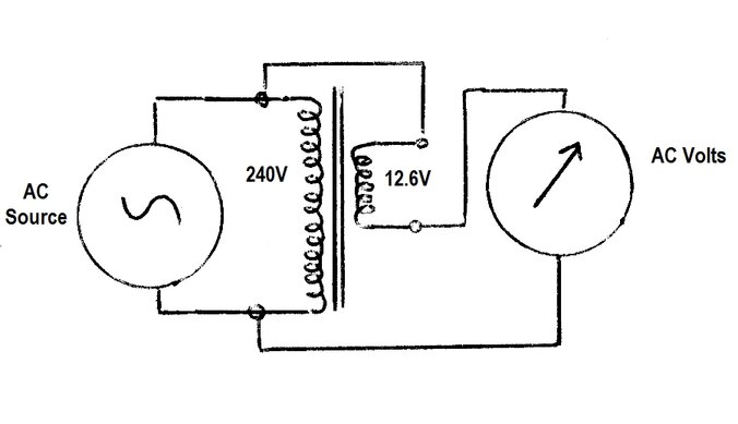
How to phase the transformer windings.
The point of connecting the 12.6V secondary
in series with the 240V primary is simply to obtain more inductance, since
all the windings are now used. However, the direction of the windings is
important. With one winding phased correctly with respect to the other,
the inductance will increase. If incorrectly phased, the inductance is
reduced. There is no way of knowing just by looking at the transformer,
which way round the windings need to be connected, so this has to be determined
experimentally.
Connect up the above circuit. The AC source
could be an audio oscillator, low voltage AC source - e.g. 12V plugpack,
or if care is taken, the mains supply itself. Obviously, if the mains is
used, the voltmeter needs to be suitably rated; e.g. the 500V AC range
on a multimeter.
Measure the voltage and take note. Then
reverse the connections to the 12.6V winding. If the voltage increases,
this is the correct connection. If it decreases, the 12.6V winding needs
to be reversed back. The common connection between primary and secondary
can now be made permanent, simply by soldering the wires and covering in
heatshrink tubing. Similarly, the unused secondary centre tap connection
can be covered in heatshrink since it is not used. (Cutting wires off transformers
is an undesirable practice).
If an inductance meter is available, this can be used instead, simply making the connection that results in most inductance. If this all sounds too hard, just use the 240V winding on its own - the difference is hardly noticeable. Of course, plenty of other transformers could be used besides the 2851. Similarly, valve radio filter chokes or speaker transformers are another option. Typically, an inductance range somewhere around 8 to 10 Henries is suitable. Importantly, the DC resistance must be high enough to keep line current below about 50mA. If not, extra resistance must be added.
First Circuit.
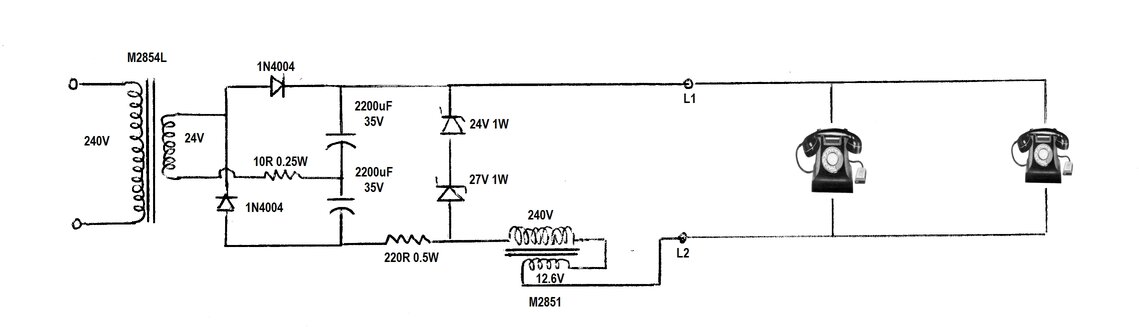
First attempt at an improved mains powered intercom.
The above circuit was built up and worked very well. The first challenge was the 50V DC supply. With the transformers I had available, and taking into account what is easily obtainable if bought new, I decided on the Altronics M2854L. This provides 24V at 150mA. The intention was to use a voltage doubling rectifier. The other type of transformer considered was the Jaycar MM-2007, which provides 30V at 150mA. Rectifying this directly would provide 42V DC. It's a big improvement on the 33V of the ETI-291, and would be quite usable, but the goal was to get the best performance; i.e. 50V. To obtain 50V DC from a simple rectifier and capacitor circuit would require a transformer of 36V, which is not commonly available in low current types.
The voltage doubling rectifier worked perfectly with the 24V transformer, providing about 68V on no load. To provide protection against a shorted rectifier diode, a 10 ohm resistor was included in series. It is rated at 0.25W, to act as a fuse. A conventional fuse of about 250mA - 315mA, could be used instead.
Since 68V is too much to feed into the
telephones, it has to be reduced to 50V. The simplest way is a zener diode
regulator. Choosing conveniently available parts, one option is to connect
a 24V and 27V zener in series to provide 51V. Three 12V, and one 15V zener
would achieve the same result. I used the 24V and 27V zener combination.
Next thing is the series resistor. This
needs to be the highest value that provides 50V across the zener diodes
with normal line current (i.e. both phones off hook). Too low of a resistor
will draw unnecessary current from the power supply, and possibly overload
the zener diodes. Too high of a resistor will provide insufficient line
current.
In this instance, 220 ohms was about right,
with 32mA of zener current with the phones on hook. This means a dissipation
of 1.6W across the zener combination. Per zener diode, this equates to
720mW for the 24V zener, and 810mW for the 27V zener. We can see that a
minimum of a 1W rating is required per zener. I used what was gross overkill,
with a 10W 27V zener, and a 20W 24V zener, since I had them available.
If buying new, 51V 5W zener diodes are a simpler, but more expensive alternative.
With the rectifier now loaded by the zener
regulator, the input voltage was now 57V, which reduced to 55V with both
phones off hook. The zener voltage dropped from 50.4 to 46V with the phones
off hook. The 220 ohm resistor is rated at 0.5W, so it too can act as a
fuse, should one or both zener diodes fail short circuit.
The circuit worked perfectly, as far as
all the required operating characteristics were concerned. Even with three
phones connected, there was no reduction in performance. However, I was
not entirely happy with the regulator circuit, in that the zener diodes
ran hot. Also the continuous current draw, whether the phones were in use
- or not, which is most of the time, seemed wasteful. This is the disadvantage
of a shunt regulator. The power supply operates as though it's under full
load, whether the load is actually in use or not!
Despite the 10W and 20W zener diodes I
used, they still became too hot to touch. I had thought that no heatsink
would be required in view of such high ratings, but this was not so. While
they would have probably been within ratings in terms of the junction temperature,
it's a fact that the hotter they run the less reliable they will be. It
would have been a simple matter to install small heatsinks, but the always
full current draw still bothered me, especially as I now pay 40 cents per
kW. $17 per year for something that might only be used for a few minutes
over that time is hard to justify, when it can be improved upon. Having
said that, if none of that is of concern, by all means build this circuit.
Improved Circuit.
I decided to fix both problems with a
series regulator. Three terminal regulators, such as 7824 and LM317, were
not used because their 37V input rating would be exceeded. Note this limitation
with the ETI-291. It is true that they can be adapted to higher voltages,
taking care to ensure the difference between input and output does not
exceed 33V. I felt this too risky, especially in a circuit with possible
inductive surges floating around. Instead, a simple zener diode - transistor
regulator was chosen. High voltage transistors are readily available.
Series regulator is more efficient.
The rectifier is the same as before, but
the shunt regulator is replaced with a series pass transistor. By doing
so, the zener current is a fraction of what it was before, since it only
has to provide base current for the transistor. The zener current is now
6mA with the phones off hook. This means only 300mW dissipation across
the zener diodes. Half watt types can be used without any heatsinking.
With the phones in use, this of course drops, as the input to the regulator
falls from 66V to 55V.
The transistor chosen was a BD139 in view
of its 80V Vce rating. Plenty of other types could be used instead. Dissipation
is only 150mW with the line shorted, and no heatsink is required. The 56
ohm resistor was included as a precaution. Since 1100uF charged up to 66V
can provide a high discharge current, it was felt best to limit the BD139
current, if anything untoward should happen. The resistor will also act
as a fuse if the transistor and zeners all fail together. It is rated at
0.25W. The 100uF serves to prevent inductive spikes getting into the transistor,
and to present a low impedance to the supply.
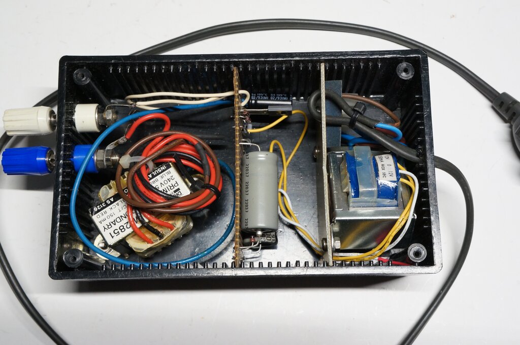
Construction of the final design.
A final improvement was the NE-2 neon bulb
across the line connections. There is quite an inductive spike if the line
is shorted and opened, and although telephones are designed to handle this,
it's best avoided for long term reliability. The neon bulb clamps the line
voltage to 90V (depending on the actual neon tube), which is much higher
than the ringing voltage, and of course the speech voltage (about 1V).
Indeed, the bulb can be observed to flash upon operating the gravity switches.
Actual measured clamping voltage was 120V.
| Line current (off hook) | 38mA |
| Line current (short circuit) | 45mA |
| Line voltage (open circuit) | 50V |
| Ring voltage | 77V p-p approx. |
| Transformer secondary current @ 24V | 90mA AC approx. |
| Rectified DC | 66V (on hook), 55V (off hook) |
Alternative Power Supply.
With the prevalence of Power over Ethernet
equipment, commercially made 48V power supplies are readily available.
This will simplify construction, since only the 2851 transformer, neon
tube, and 100uF capacitor are required.
1) Series 800 (mechanical dial). The common mechanical dial versions are the best performers, and will operate satisfactorily with 30V.
50V is required for types listed below:
2) Series 800 (push button dial - "Touchfone"). Works as per the mechanical dial version, but needs 50V for dialling. Be careful not to confuse with the last generation of 800 which was fully electronic, and will not not ring.
3) Series 300/400. Works well. While not actually tested, earlier types such as 37, 162, candlestick, and wooden phones should also work.
4) Series 700 (706,746, etc). Works well.
5) Ericofon. The mechanical buzzer of an Ericofon does respond, but is not loud enough to be heard except in a very quiet room.
6) Gondola. Two of these were tested, and worked so far as the dialling and ringing were concerned. One rang noticeably better than the other, which could be due to bell adjustment. However, the transmission quality was poor. Like the Gold Phone, the line voltage was too low due to unequal current sharing, and the cure was the same; i.e., a 330 ohm resistor bypassed with a 100uF capacitor, connected in series with the 400/800, etc.. Best results were with both phones being Gondolas.
7) Red Phone. The Red Phone dialled and rang reliably, but you might not hear its bells outside of the room. An interesting possibility would be to include a reversing switch to operate the coin collection mechanism.
8) Gold Phone. Initially, the Gold
Phone worked to some extent, in that its ringer responded reliably, although
quietly - but it isn't very loud with normal ring voltage anyway. Dialling
from the Gold Phone could ring an 800, but not a 400. This is because of
the peculiar dialling characteristics (described
here), which mean less of a 'ring' voltage being generated. The real
problem is due to the limitation of the common choke feed, since the conventional
phone causes the line voltage to drop to something like 4 to 7V. The Gold
Phone cuts off with less than about 12V. In view of this, what if both
phones were Gold Phones? This was successful, with good transmission between
the two. The ringing is quieter than when a conventional phone does the
dialling, because of the 17V dialling offset of the Gold Phone. If you
were sitting at a desk with the phone you'd hear it, but not outside the
room. A separate extension bell of the 800 type across the line would be
an easy way to improve this.
All was not lost, because it was
possible to use an 800 with a Gold Phone. Simply connecting a 330 ohm resistor
in series with the series 800 phone jacked up the line voltage sufficiently
(adding another 10V), so that the Gold Phone could work. The resistor needs
to be bypassed with a capacitor (e.g. 100uF 25V), with attention to polarity.
9) Ericsson/Plessey Portable Linesman's Telephone. This telephone works well, but line polarity is important with the battery feed models. L2 must be connected to the line positive, with the battery connections shown in the phone. This is because the internal battery will subtract from the line voltage with 'incorrect' polarity, resulting in a line voltage of only about 1.5 to 2.5V. The result is poor operation.
Anti-Tinkle Module.
While seldom encountered, some telephones
during the 1980's were fitted with Telecom's Anti-Tinkle Module, to allow
compatibility with two wire operation. Since their purpose is to prevent
the bell responding to dial pulses for two wire working, they should obviously
be disconnected (but left inside the phone for historical purposes). Similarly,
a few 300/400 series phones were fitted with thermistors for the same purpose.
Installation & Earthing.
One convenient aspect of installation
is that the power supply can be located at some distance from the phones,
since the same two wire feed connects to both phones. This means, for example,
the power supply unit can be placed near a power point, and cheap low voltage
cable run to wherever the phones might be, without any shock hazard. The
power supply does not need to be at one of the phones.
For a simple domestic intercom circuit
like this, it is not necessary to earth one side of the DC power supply.
However, if there are long runs of cabling, it may be desirable to do so,
for some degree of lightning protection, or to reduce hum pick up. Normal
telephone practice is to earth the positive side of the supply, since this
is more favourable from a corrosion perspective. In this instance, if an
earth is used, connect it to the L1 terminal.
Obviously, if the unit is built in a metal
enclosure, this should be earthed through the mains cable.
Further Experiments.
Attempts to replace the choke with a resistor
worked, but with a reduction in performance, and is not recommended. The
bells on the series 400 phone were not as loud, although the series 800
seemed largely unaffected. This is not surprising, given the reduction
in ring voltage. For those that want to try it, a suitable resistor is
820 ohms 5W.
Using separate chokes for each phone improved
transmission quality, but detracted from the ringing performance. The coupling
capacitor needs to be non-polarised, and at least 10uF for the ringing
to work. I tried a pair of 100uF 100V electrolytics back to back, but the
ringing performance was still inferior to the single choke circuit. It
appears the problem might be that with two chokes effectively in parallel,
the inductance is halved. All things considered, the circuit as described
works best for its simplicity.
Conclusion.
The circuit achieved the desired results,
and is an excellent performer. It will operate at least three phones. With
an 800, a 746, and a 400 connected together, all phones dialled correctly
and rang loudly. It was also possible to have a three way conversation.
How many phones can actually be connected, with reliable ringing, has not
been tested. In this regard, series 800 phones with their sensitive bells,
would allow the greatest number to be connected.
For more than two phones, coded ringing
as used with party lines could be implemented. For example, dial 0 for
house, 4 for shed, 2 dialled twice for workshop.
Connections.
For the series 800 telephone, the connections
are as follows: L1 (L+) is the white wire connected to pin 2 of the plug.
For the bell to ring, pin 2 must also be connected to the red wire at pin
3. Normally, there is a strap in the socket between pin 2 and 3 for this
purpose. L2 (L-) is the blue wire connected to pin 6 of the plug. The black
wire (if fitted), connected to pin 5 is not used. Some phones might also
have a green and orange wire, which are also not used. Note that if the
telephones used have come from a parallel (three wire) installation, various
jumpers inside the phones will have to be rearranged, to bring the phone
back to single connection operation. Of course, the 891 wall phone does
not use a plug and socket, but is otherwise configured as per the 800 table
phone.