This telephone exchange design appeared
in the February 1975 issue of the English electronics magazine, Practical
Wireless. Corrections were issued in March 1975. It allows for the connection
of nine automatic telephones. The design is a very simple one with limitations,
but it is functional and practical. While it does allow each of the telephones
to call each other, it differs from the normal public exchange in a number
of ways.
In March of 1976, a modified version of
the exchange appeared, which eliminated the reed relays used in the original
version. Corrections to this design were issued in August 1976. See link
at end to download these articles.
The intention of the exchange was to function
as a stand alone system. It is not suitable for connection to the public
network.
Anyone who was a student of Electrical
Engineering at North Sydney TAFE during the late 1970's - early 1980's
may remember the black bakelite 400 series telephones installed in the
classrooms. Several of the PW exchanges had been constructed, and the phones
were connected to these. By the time I started as a student in 1985, the
PW exchanges had been taken out of service and replaced with a Myphone
intercom system.
However, all the remaining 400 series
phones, and two exchanges, came into my possession when I became an employee
of the Electrical Engineering section. One exchange is the original reed
relay version, and the other is the later version with no relays.
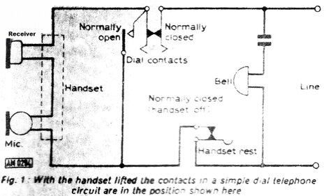
This circuit omits such refinements as
the anti side tone induction coil, but demonstrates the basic features.
The bell is across the line in series with a capacitor so that it does
not normally load the line. The capacitor, of course, appears as an open
circuit on DC, so that the line is not looped. When the approx. 75V 16.66Hz
ring voltage comes down the line, the capacitor allows the AC to pass through
the bell causing it to ring. Typically, the bell is 1000 ohms and the capacitor
is about 2uF.
When the handset is taken off the hook
switch, current of about 20mA flows through the transmitter and receiver,
allowing the transmitter to modulate the line current with the user's voice,
and the receiver also passing the line current, allows sound from the distant
telephone to be heard.
During dialling, the handset is short
circuited by a set of contacts on the dial, which remain closed whenever
the dial is rotated. This is to prevent the resistance of the speech circuit
causing a less reliable dialling function, and prevents loud clicks being
heard in the receiver. As soon as the dial is rotated anti clockwise from
the finger stop, the entire phone appears as a short circuit. When the
dial is released, the normally closed contacts open and close rapidly (typically
10 pulses per second), and the phone appears as an open circuit when the
contacts open. Of course, the number of openings and closings corresponds
with the number dialled.
Simple Intercom.
In the most basic form, an intercom can
be made from two automatic telephones connected together. By connecting
them via a common impedance to a power supply the speech circuits will
be powered, and a crude form of signalling becomes available.
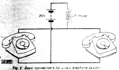
The impedance (designated LF [low frequency]
choke) isolates the power supply from the AC component developed across
the line by the speech circuits. Without it, the speech signals would be
short circuited by the power supply, although the individual phones would
be powered. In most telephone exchanges the supply is 48V, and the DC resistance
of the impedance, along with that of the line resistance between the exchange
and the subscriber, limits the current to around 35mA. Small exchanges
sometimes use a 24V supply.
With the above circuit, when both handsets
are taken off hook, conversation is possible since the transmitters at
each end modulate the line current.
To signal the other phone, a number is
dialled from the calling phone. The actual number dialled is unimportant,
since there is only one other phone, and there is nothing to count the
dial pulses. Each time the line is short circuited and open circuited by
the dial, it can be seen that the capacitor in series with the bell will
charge and discharge in time with the dial pulses. Thus the bell will ring.
Obviously, the bell in the distant phone will only ring as long as the
calling phone is being dialled from. It should also be obvious that if
"1" is dialled, the bell will ring once, and conversely if "0" is dialled,
the bell will ring 10 times. The ringing frequency is also of course the
same rate at which the dial contacts open and close; i.e. 10 pulses per
second. In fact, this circuit exploits the usually undesirable 'bell tinkle'
when phones are connected in parallel across a line incorrectly.
This simple intercom is quite practical if only two telephones are required. Electronics Today International (Australian edition), for February 1988, presented their ETI-291 telephone intercom which operates on this principle.
A two subscriber exchange has also been described elsewhere on this site, but for central battery telephones. Automatic phones can be used for one or both subscribers, but the dial is not used.Multiple Phones.
An expansion of the above circuit allows
for more than two phones with individual signalling.
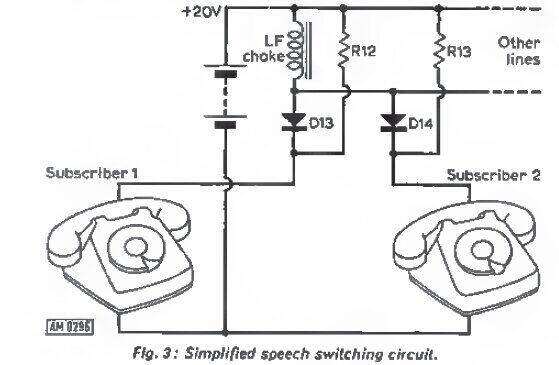
As previously, a common 20V power supply
and choke are used. As many phones as required can be connected.
Each phone is isolated by a diode so that unless it's off hook, the diode
is reverse biassed and appears as an open circuit. The pull up resistors
ensure the diodes are 'off' unless the relevant phone is in use. In this
circuit it can be seen that if both phones are off hook, that D13 and D14
will be forward biassed, and speech current can flow between the two phones.
This circuit is theoretical, since it does not allow for signalling between
the phones - it merely demonstrates speech switching. The diodes are necessary
to isolate the ringing signal between phones, as will be described.
Individual Ringing.
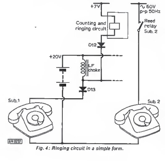
To the speech circuit of Fig. 3, a ring
circuit can be added. When Sub.1 dials '2', D13 and D12 conduct causing
Sub. 2's reed relay contacts to close, feeding 60Vp-p into the phone, causing
the bell to ring. Once Sub.2 lifts the handset, the speech circuit is completed
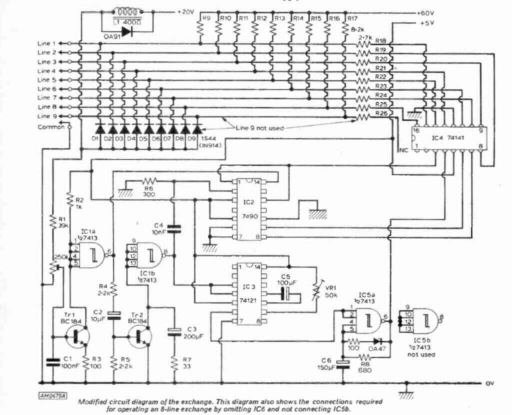
as previously described. Below, the circuit shows the concept expanded
to accommodate nine subscribers.
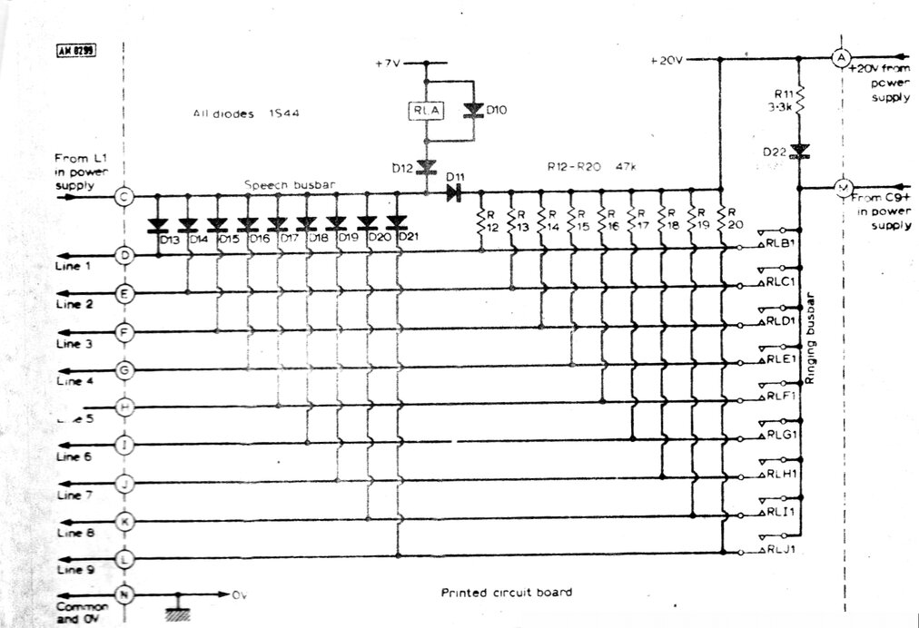
Note that D10 is incorrectly shown connected in reverse. The
line numbers should also be reversed.
The AC ring voltage comes in at terminal
'M' and is switched to any of the nine phones by relays B to J. The diodes
D13 to D21 have been previously described, as have resistors R12 to R20.
RLA is the relay coil which responds to the dial pulses. D12 along with
D13 to D21 function as a nine way OR gate. Any of the nine phones that
is dialled from will cause RLA to respond to the dial pulses. Each time
the dial contacts open (or the handset is on hook) D12 is reverse biassed,
since RLA's 7V supply is less than the 20V speech supply. Therefore, the
relay is de-energised. When any of the handsets are off hook, the voltage
across each phone is high enough (roughly 10V), so that D12 is still reverse
biassed and RLA does not respond. But, when dialling commences, the voltage
across the phone falls to 0V, so D12 becomes forward biassed since the
phone voltage is much less than 7V.
D11 isolates the pull up resistors from
the speech circuit, so that D13 to D21 are turned off unless the relevant
phone has looped the line. D11 appears to be superfluous since there is
already a current path via the choke which is connected across D11, and
indeed the exchange appears to work normally without it. The ring voltage
is isolated by a capacitor (C9). By means of D22, this capacitor is kept
charged at 20V, ensuring that the peak of the ring voltage does not go
below +20V. This prevents any of speech routing diodes to conduct, which
would otherwise put ringing voltage onto the speech busbar.
Dial Counting Circuit.
The next part of the circuit required
is something to count the dial pulses and activate the relevant relay.
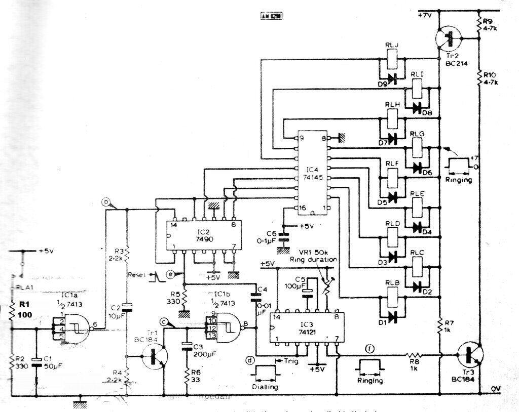
As we have seen from the previous circuit,
RLA responds only to the dial pulses. The contacts of RLA feed the input
of a 7413 Schmitt trigger via an input filter consisting of R1, R2, and
C1. This part of the circuit is necessary, since mechanical dials cause
contact bounce and would otherwise erratically trigger the counting circuit.
Pin 6 of the 7413 provides definite pulses corresponding to the number
dialled from any of the phones.
From the 7413, the pulses feed the input
of a 7490 decade counter. This provides a BCD output corresponding to the
number dialled. This BCD output is converted to decimal by the 74145. Thus,
if '3' is dialled, the corresponding output of the 74145 goes low (pin
4). RLD's coil is actuated, switching the ring voltage to Subscriber 3,
as previously described. (A point of note is that both the 7490 and 74145
could probably be replaced by a single 4017, provided the 4017 can sink
enough current to switch the relay coils).
Relays RLB to RLJ which switch the ring voltage to Subscribers 1 to 9 respectively, can only be actuated when Tr2 and Tr3 are conducting. Tr3 is biassed on when the output of the 74121 goes high. The 74121 is a monostable, which is wired so that the duration of pin 6 being high is determined by VR1 and C5. When the 74121 is triggered after a number has been dialled, the relevant ring relay is activated for a short period set by this RC time constant. VR1 allows the ring duration to be set from 1 to 5 seconds.
The final part of the counting circuit is based around Tr1 and the other half of the 7413 Schmitt trigger. The squared up dial pulses are also fed into TR1 which inverts them and feeds the input of the 7413. Note C3 at the input of the 7413. This prevents it responding to the individual dial pulses, but will allow the 7413 to trigger once dialling is complete. R6 limits the collector current of Tr1 each time Tr1 conducts and discharges C3. In summary, IC2 counts the dial pulses, whereas IC1b determines when the dialling is complete.
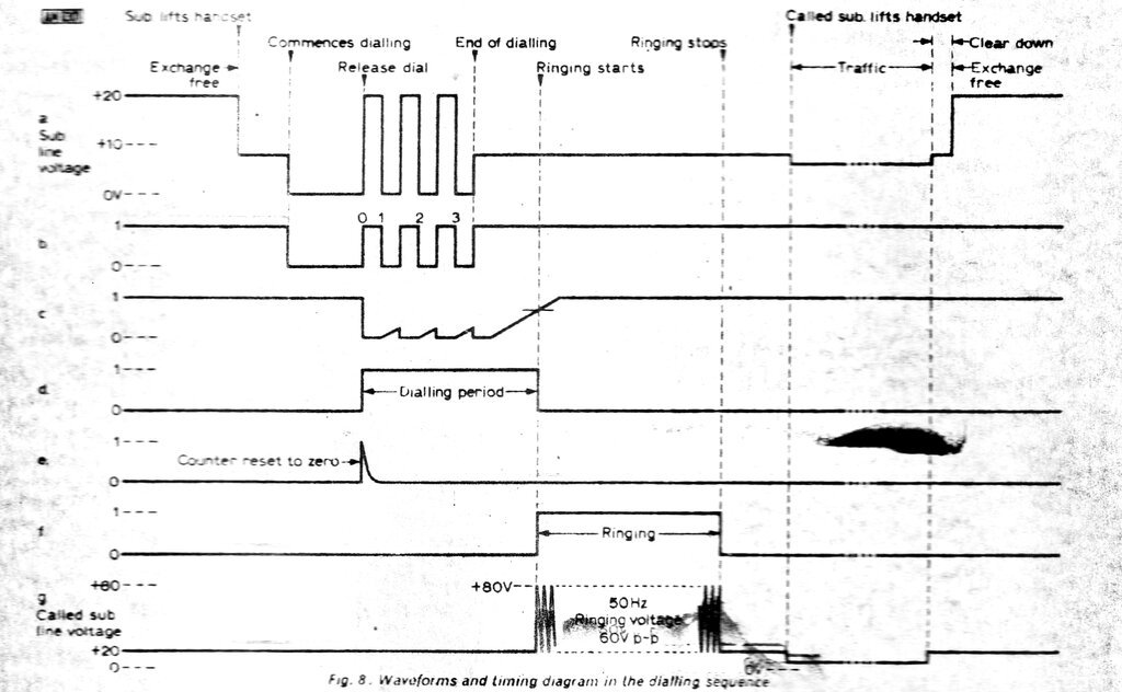
Dialling and ringing waveforms.
The circuit can be basically summed up
as counting the dial pulses, and routing the AC ring voltage to the required
phone for up to 5 seconds, as set by VR1.
An obvious difference to normal practice
is that the called phones rings once for a fixed period, and not continuously
until the called phone is answered. If there is no immediate answer, the
number has to be dialled once again to ring the called subscriber. In practice,
for the applications this exchange would be used for, this should not be
too much of a limitation. To provide circuitry for continuous ringing would
complicate the design somewhat, since more circuitry would be required
to detect when the called phone is taken off hook during the ringing. Since
this simple ringing circuit does not provide for off hook detection, it
can also be seen that ring voltage would be fed into the speech circuit
of the called telephone, if it should be answered within the ring duration.
However, the reactance of the ring isolating capacitor (C9) would be high
enough to prevent any harmful effect.
Power Supply.
The final part of the exchange circuit
is the power supply circuit.
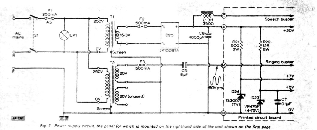
The +20V for the speech circuit is obtained
from rectifying the secondary of T1 and filtering it with C8. The common
impedance for the speech circuit is L1, a 3 Henry choke with a resistance
of 350 ohms. The +7V relay and +5V logic supplies are obtained with simple
zener diode regulators. In my particular exchange, the choke had been substituted
with a 250R resistor. This appears to work just as well.
Ring voltage comes from T2 and is DC isolated
by C9, which is 8uF. With the specified 20V secondary, the ring voltage
is almost 60Vp-p. It should be noted that this is 50Hz and not the 16.6Hz
which telephone bells are designed for. Again, this is done for simplicity.
Most mechanical bells will work from 50Hz;
more so if adjustment is available.
Those familiar with telephone practice
will notice the circuit is negatively earthed, whereas normally, telephone
circuits work with a positive earth to reduce corrosion effects. There
would be little point in modifying the circuit for positive earth for such
a simple design, given the applications it would be used for.
Differences to Normal Practice.
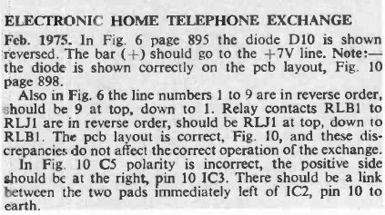
Fig. 10 is the PCB layout, not shown in this article.
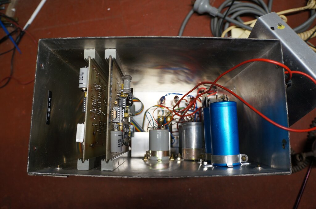
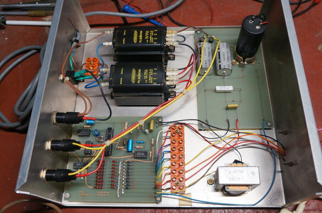
Components of exchange. Wiring for one of the PC boards has been
removed.
Testing the Exchange & Fault
Finding.
Three phones were connected for testing;
a 700, 400, and 800. Since the phones were close together, using different
types makes it easy to identify which one is ringing. The 400 didn't ring
properly on 50Hz (and I didn't want to adjust the bells), so later replaced
it with an Ericofon to make the demonstration video.
It was found that phones with electronic
push button dials would not work. The reason being that the dialling supply
is only 7V, and there's too much voltage drop across electronic phones.
Alas, there seemed to be some problem with
the dial counting circuit. None of the phones would ring when dialled.
The phones could be made to ring by applying current to the relay coils,
so that confirmed the ring supply was present. The 74121 monostable was
working in that the output went high after each dialling attempt. Narrowing
it down, it seemed the problem was with the 7490 and 74145, or ancillary
components controlling the 7490.
It was noticed that the 5V supply dropping
resistor had been replaced with something temporary, which happened to
be 200R. The 5V supply did fluctuate during dialling, so I replaced the
resistor with 120R. This improved regulation, but did not fix the problem.
By removing the 7413 from the board, and
feeding a function generator producing a 5V square wave into pin 14 (clock)
of the 7490, it was determined that the 7490 and 7415 were OK. Furthermore,
by forcing the 7V rail to be on all the time (by shorting Tr3) the phones
would ring in succession as the 7490 counted through the relevant subscriber
number.
This narrowed down the problem to the
7413 and/or Tr1 part of the circuit. The 7413 was tested by substitution,
but of course didn't fix it.
Instead of the function generator, the 7490 input was then restored to the first half of the 7413, (IC1a). The second half (IC1b) was disabled by shorting out the base of Tr1 (short circuiting R4). At this point, each telephone successfully operated the counting circuit. By repeatedly dialling '1', each of the phones could be made to ring in succession. Tr3 was still shorted to enable the 7V ring relay supply.
There was not a lot of parts left to test. Knowing the 7413 was OK leaves Tr1, C3, C4, and R5 and R6. I doubted any kind of design fault as such, because testing the other 'solid state' version of this exchange showed this part of the circuit to work well.
Next thing was to short out R5 which is
at the reset pin of the 7490. With Tr1 and Tr3 restored to normal operation,
the counter worked as shown again by being able to ring each phone in succession
by dialling '1'. So, it seemed we had a reset pulse problem.
Connecting a LED to pin 8 of the 7413
showed it to flicker as the phones were dialled from. This is not correct
since the 7490 is being reset on each dial pulse! As C3/R6 is meant to
filter out the dial pulses, these components were next to check.
C3 and R6 checked OK, and rapidly shorting
the collector to emitter of Tr1 did in fact show the C3/R6 time constant
was working, since pin 8 of the 7413 remained steadily high. Next was Tr1
and it too tested OK. Perhaps it wasn't being driven correctly, and here
I had some luck. C2 measured .082uF instead of 10uF. Obviously, Tr1 wasn't
being driven hard enough to fully discharge C3 during dialling. With C2
replaced, we at last had a steady output at pin 8 during dialling. But,
still no ringing! The 74121 was operating since the 7V ring relay supply
was being switched on after dialling. I soon discovered that pin 8 was
going high during dialling, only if the CRO probe was connected. It turned
out that it was the capacitive loading of the CRO probe which was allowing
it to work, and not the resistive loading. Indeed, connecting a 270pF capacitor
to earth from pin 8 made the monostable and ring supply work correctly.
This shouldn't be needed, and was obviously
covering up some other fault. Furthermore, the 7490 was not counting correctly,
because even though the 7V ring relay supply was activated, the correct
relay was seldom switched on.
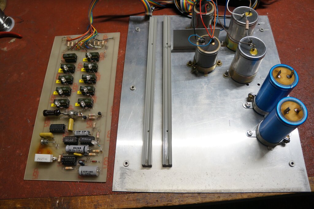
Fault finding LED's added to PC board.
In an effort to make fault finding easier,
a LED with 6.8k resistor was connected across the coil of each relay, and
at the output of the monostable. At a glance it could be seen what the
counter was doing, and when the 7V ring relay supply was present.
An interesting discovery was that counting
and relay operation was correct for lines 4 to 9, even when repeatedly
dialled. 1 to 3 were erratic, as was the 7V ring relay supply. And, it
just so happened that lines 1 to 3 were the ones with phones connected.
Suspicious now, I transferred the phones to 7,8, and 9. The fault went
with them - now lines 1,2,3 dialled correctly, but 7,8,9 were erratic.
Evidently, the loading of the phones was causing some kind of reset.
Perhaps the ring current flowing back through a bad earth connection or something similar was causing the reset. Disconnecting the AC ring supply provided an interesting result. Not only could each number be dialled correctly all the time, including the three lines with phones connected, but the capacitive loading on pin 8 of the 7413 was no longer needed. Aside from the absence of ring voltage, everything was now working.
Looking at the AC ring supply, I then noticed that R11 and D22 were missing from the PCB. They had obviously been there before. Replacing them didn't entirely fix the problem, however. The 400 series phone could be dialled reliably. The 800 some of the time, but the 700 always caused a reset when it was dialled. This was confirming my theory, seeing as the bells are of different impedances. Indeed, connecting a 250R resistor in series with the 700 allowed it to be dialled reliably all the time. Too much bell current?
Ring Voltage Problem.
The power supply, as constructed, differs
from that published. The transformer is a Ferguson PL30-9/40VA. The two
15V windings are connected in series (30V) which is then half wave rectified,
and regulated with a MJ3055 and 24V zener diode, producing about 23V for
the speech circuit. The ringing supply was the 9V winding in series with
the 30V, producing 39V for the ring voltage. As published, the design had
a 20V ring supply. As a test, I took the 9V winding out of the circuit,
dropping the ring supply back down to 30V, and at last all phones could
be reliably dialled. My guess is that the higher voltage, along with the
inductive nature of the bells, was causing enough of a spark at the relay
contacts to interfere with the TTL IC's.
At 30V, the bells don't ring as well,
but it's important to note that they haven't been adjusted for 50c/s. Importantly,
the exchange was now working. I tried restoring the 39V ring supply, but
connecting a 270R resistor in series to reduce the contact arcing. This
seems to work, allowing more ring volume.
A Bit of History.
The file for this project shows that it
was requested by one of the teachers in October 1975. Three PCB's were
requested; it appears two went into the exchange that was built up, since
there's an undrilled PCB in the files.
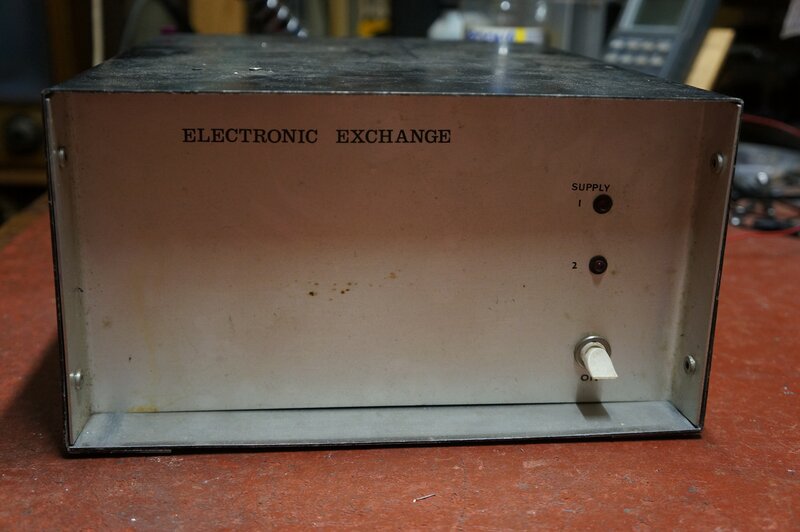
The aluminium enclosure actually holds
two exchanges - each with their own transformer, 250R 8W resistor (instead
of a choke), and AC isolating capacitor. When I acquired it, something
like 25 years ago, I removed the components for one of the exchanges. As
I vaguely recall, the whole thing was very untidy and I suspect one of
the exchange PCB's had been added at a later date. I removed it along with
its ancillary parts, and relocated the remaining transformer to tidy it
up. I think at this time I added the extra 9V into the ring supply, since
it gave a louder ring. I still had the parts removed, which also included
two filter capacitors, so I suspect there had been another DC supply regulator.
This would appear unnecessary since both exchanges could have been
run off the one transformer and DC supply. I decided to put all the extra
parts back, for the sake of originality, but did not reconnect the second
exchange board. This can easily be done if the need should ever arise.
Boards slot into case.
I had been told by a work colleague that
reliability was problematic when these exchanges were in service. Apparently,
there were problems with the reed relays sticking - and indeed one of them
did stick during my fault finding. When this happens, the bell of the affected
phone rings continuously. I could not find any data on the relays, except
to know they have 5V coils.
The speech isolating diodes had all been
replaced with 3A rectifier diodes. I suspect the original 1N914's had been
damaged due to lightning. Some of the lines would have been at least 100m
long, and would be susceptible to nearby lightning strikes.
The wiring between the exchange and the
phones was certainly a departure from normal telephone practice. Single
lengths of hookup and 240V rated wire had simply been run to each phone.
It was a very untidy bundle of wiring when I removed some of it from the
ceiling space. No sockets or terminal blocks had been used at the phones.
Instead, the two wires were run down a length of black plastic tubing from
the ceiling directly into the phones. A Dymo label attached to each phone
stated, "Dial 9 for technician".
The first rooms connected to the exchange
were; 1- BG16 (technicians), 2- BG10, 3- BG15, 4- BG14, 5- BG13, 6- BG12,
7- BG11, 8- BG01 & BG02, 9- BG06.
A remaining label attached to the side
of the exchanges gives room numbers where the phones connected to the 2nd
PCB were; 1- B241, 2- B238, 3- BLG18, 4- BG16, 5- BG36, 6- B233, 7- BG41,
8- BG38, 9- Darkroom.
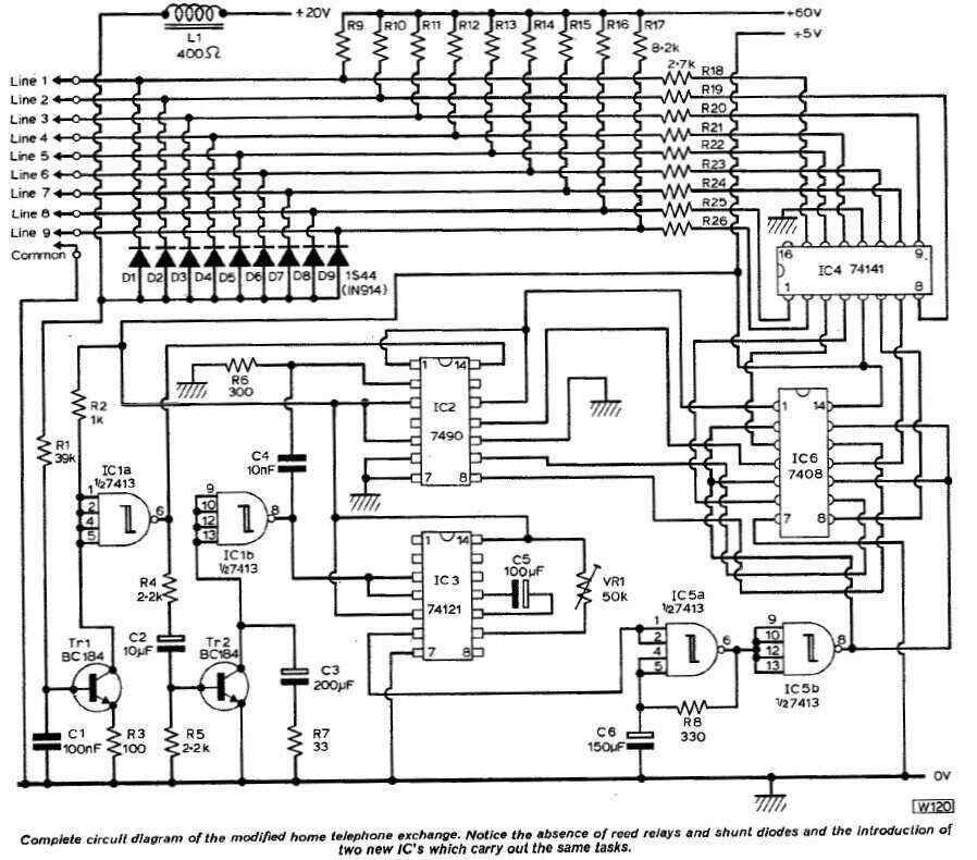
Terminal blocks for connecting the phone lines.
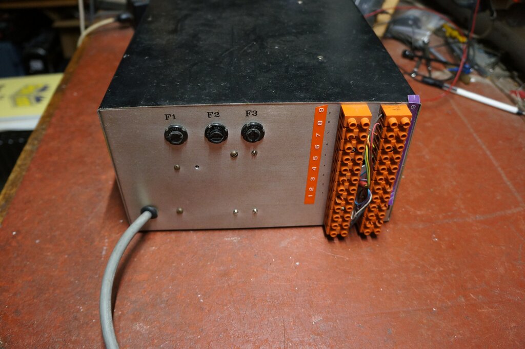
A modification had been done to the ring monostable circuit.
When a phone is answered, point 'M' goes
low which causes the PNP transistor to conduct, connecting 5V into pin
10 where the capacitor is connected. It appears that the intention is if
the phone is answered during the ring duration, the 100uF is immediately
charged, cutting off the ring supply. This prevents the loud AC ring voltage
being heard. I did not analyse this further as the modification had been
removed from the PCB still connected.
The ring period preset pot had been replaced
by a fixed 39k resistor. This is sensible as the need to make the ring
period adjustable seems pointless. File notes suggest the ring duration
is 4.25 seconds.
Self Test.
Though probably never intended by the
designer (and not mentioned in the original article), it is possible to
get any of the phones to ring back to itself by dialling its own number.
For this to work, the phone must be hung up immediately the dial stops.
Possible Improvements.
A 16Hz ring generator would allow any
phone to ring normally. This can be achieved with a simple phase shift
oscillator and power amplifier driving a step up transformer.
The relays should be upgraded, although
they might operate reliably now that the 270R resistor is in series with
the ring supply. An interesting possibility would be to use Triacs to switch
the AC ring voltage.
A loop detect on answering circuit would
allow continuous ringing.
Increasing the supply voltage to the dialling
relay would allow push button diallers.
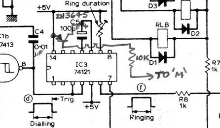
"A Solid State Version - Home Telephone Exchange."
This project appeared in Practical Wireless for March 1976, as a perceived improvement to the previously described design. In the new design, a cost saving and simplification is obtained by eliminating all the reed relays. In September 1976, a request was put in for the new version to be constructed by the technical staff.
This circuit operates on the same principles
as the previous one, but the main difference is with the ringing circuit.
To begin with the dialling circuit, there is no longer the dial sensing
relay, RLA. The input of Tr1 is now fed from any of the phone dials via
OR gate consisting of D1 to D9. As the line is shorted during the commencement
of dialling, the base of Tr1 is taken low. As the dial contacts open during
each pulse, Tr1 is fed base current via R1 and conducts, pulling down the
input to the Schmitt trigger, IC1a. C1 partially filters the contact bounce
of the dial. As before, the output of the Schmitt trigger feeds the 7490
for counting the pulses, and also the 74121 monostable which activates
the ringing mode.
Up to this point, the circuit works the
same but with one relay eliminated.
IC4 is a BCD decoder which is designed
to switch the cathodes of Nixie tubes, and so has a much higher voltage
rating on the output transistor collectors, compared to the usual TTL IC's.
This allows this IC to directly switch the ringing voltage, which now comes
from a +60V supply.
However, between the outputs of IC2 and
the inputs of IC4 is a 7408 quad AND gate. One of each input of the AND
gates is fed from the BCD output of the 7490, and the outputs feed into
the BCD to decimal decoder, 74141. Provided that the other inputs of each
AND gate is taken high, the circuit works as before, and the 7408 simply
conveys the BCD output to the decoder.
But, the other AND gate inputs are fed
from IC5. This is another 7413 Schmitt trigger wired as an astable multivibrator.
By means of C6 and R8, it oscillates at about 16Hz - which happens to be
the ideal bell ringing frequency. IC5 oscillates only during the ring period
which is controlled by IC3.
Now, it should be clear that the BCD to
decimal decoder is actually gated by the 16Hz signal, so that instead of
permanently going low during the ring period, it goes high and low at 16Hz,
for whatever output has been activated according to the number dialled.
Ringing Circuit.
This is where the ringing circuit becomes
quite unconventional, since the phone bells are no longer fed with 50Hz
from the mains transformer. Instead, it is based on the simple two phone
intercom design which exploits the 'dial tinkle' effect to make the called
bell ring.
Consider the telephones on hook. The 60V
supply (actually 68V) is fed into each phone via an 8.2k resistor.
At this point, the outputs of the 74141 are high and have no effect. The
bell series capacitors charge up to 68V, since the bell completes the circuit.
As each of the 74141 outputs is taken high and low at the rate of 16Hz,
it can be seen that during the low period, the line is now taken to earth
via a 2.7k resistor. Using the voltage divider formula, we can see that
the line voltage will oscillate between +68 and +17V. Thus, the open circuit
ring voltage will be 51Vp-p at 16Hz. However, because of the bell resistance
being typically 1000 ohms, the actual bell voltage will be much less than
this. The article does in fact admit that the ringing volume is less than
the original circuit. Nevertheless, it's a clever simplification. One advantage
is that if the handset of the called phone is lifted during the ring period,
the current through the speech circuit will be much less due to the 8.2k
resistor. One could surmise a greater ring voltage by shorting out all
the 2.7k resistors. There's two reasons this would be undesirable; 1) the
discharge current of the bell capacitor might exceed the rating of the
74141, and 2), if the output is taken to ground, the dial counting circuit
will mistake the 16Hz ringing for dialing pulses.
Power Supply.
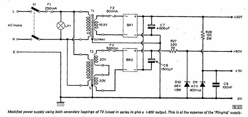
The AC ring supply is no longer used,
but in its place is the +68V supply. Otherwise, the +20V and +5V supplies
are as before. Since there are no relays, the +7V supply is also omitted.
There are two DC supplies created from the power transformers. One is 20V
and the other is about 56V. The 20V supply is used for the speech circuit,
and via R128 and D11 for the 5V TTL supply. The 56V supply is connected
in series with the 20V supply, creating 76V, which is regulated to 68V
by R27 and D10. It is strange that 60V is quoted when the zener diode is
68V.
Inside of the NSTC built exchange.
Modifications.
In August of 1976, a short article described
some improvements and modifications.
Firstly, there is now a 250k preset pot
in the base circuit of Tr1. The article does not say what this is for,
or how to adjust it. It would appear that due to line resistance, or other
small internal resistances in the phones, the base of Tr1 might not always
be taken to less than 600mV during dialling. The counting circuit would
be fed with erratic pulses. Presumably, the 250k is adjusted for reliable
dialling from all phones once the whole system is set up.
Next, the author thought the duty cycle
of the 16Hz generator could be improved, and to do this a 100R resistor
and 0A47 diode have been added between the input and output of IC5, along
with changing the 330R to 680R. Evidently, the inverting function of IC5b
was no longer required.
It will be noted that IC6 is missing. This IC can be eliminated if only eight lines are required.
The purpose of the 0A91 diode across the choke is not explained, but would appear to be used to clamp the back emf developed across the choke during dialling. Quite possibly there was a problem with the 74141 being damaged due to excess voltage on its outputs. The line voltage would be limited to 20V during dialling with the diode in place. However, in this position it would appear to also clip the speech voltage developed across the choke, limiting it to 250mV in one direction.
Testing the "Improved" Exchange.
It was a disappointment in terms of ringing
ability. This was to be expected, given the high pull up and pull down
resistors (8.2k & 2.7k). Even so, it did seem something was not right.
Three phones were connected; a series
700, 400, and 800. None of them would ring.
It was noticed that the 330R in the ring
circuit multivibrator was actually 180R. Whether this was deliberate or
a constructional mistake is not known. Replacing it with the 'correct'
330R lowered the ringing frequency which did help. The 400 series phone
would ring most of the time in a weak manner, but the 700 still remained
silent. The 800 could be heard to buzz from the bell motor, but it wasn't
strong enough for the armature to actually operate and strike the gongs.
Knowing that there had been a modification
issued for the duty cycle, this was experimented with next. Rather than
desolder and resolder components, the 7413 was unplugged, and a function
generator set for 5V was connected to pin 8 of the IC socket.
It was found that best ringing occurred
with a 50% duty cycle - the original circuit provides for a lot less than
this. Depending on the phone, best results were between 15 and 22Hz. It
was noticed the BCD to decimal decoder was a 7441 instead of a 74141. These
are pin compatible and have only minor differences in ratings.
The duty cycle was altered using an 820R
where 680R had been specified, and a 150R instead of the 100R in series
with the diode. A silicon diode was tried first, but the series resistor
was very critical. A germanium diode fixed that - obviously due to the
lower voltage drop across the germanium type. Operating frequency is now
22Hz with an approximate 50% duty cycle. The phones now ring reliably,
although not as loud as they normally would. An Ericofon did not ring at
all. Therefore, if this exchange is ever put into use, it will be with
300/400 or 800 series phones.
An electronic phone did not work at all.
Not only was its dial pulses ignored, but it did not ring. This was not
surprising given the different electrical characteristics which specifically
eliminate bell tinkle, and the higher voltage drop during dialling.
A useful self test feature discovered
is that by dialling a phone's own number and hanging up, it will ring.
It would appear that this exchange had never actually been put into use. The enclosure looked a bit unfinished; unpainted and unlabelled - which was not the norm with apparatus built at the college. At a guess, it was probably just put to one side when it was found it didn't ring the phones and was forgotten about. The updated article with modifications was in the project file, but none of them - most importantly the duty cycle improvement - had been implemented. Also, the external terminal block had only been wired to the PCB to allow for four subscribers. This suggests that it was never used for the classroom phones. It would appear the intention was for student demonstration - this seemed likely from the wording of the teacher who requested its construction.
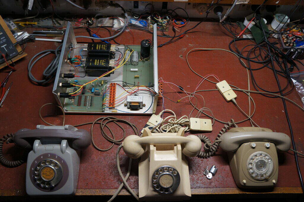
Testing with three phones; a series 700, 400, and 800. Note the
dial lock for the 400.
The exchange had been constructed largely
as per the PW article. The PCB was designed and etched by the electrical
engineering staff who built it - no PCB design was given in PW.
Measuring the power supply, it was found
the ring supply was actually 80V. The 68V zener was missing, but was obvious
where it had been. Perhaps it had been removed in an attempt to get a higher
ring voltage. In any case, 80V is better than 60V for this purpose, although
it appears the 70V collector voltage rating of the 7441 is being exceeded.
The two transformers used were a pair
of Ferguson PL30/60VA types. These are very much much overkill for the
current required, but they would have been used since they were already
a store item, and the voltages were about right. One 15V winding is rectified
and filtered for the 20V supply, and the three other 15V windings were
in series (45V AC) which when rectified (63V DC) and added to the
20V supply, provided a little over 80V. Simply bypassing one of the 15V
windings allowed the ring supply to return to the specified 60V.
The choke is an ordinary 14H 60mA filter
choke as used for valve radios.
Line current was measured and found to
be about 35mA with the 400 and 800 series phones.
The missing zener diode was replaced with two 36V 2.5W types in series (72V 5W). Ring voltage is now actually 75V due to the zener diode current. It's pushing things a bit in terms of the 7441 rating, but the 8.2k resistors would go a long way to getting away with it.
Using the exchange is straightforward. Upon lifting the handset there is no dial tone, but the presence of side tone indicates that the line is connected, and the exchange is powered up. Since there is a limitation of nine phones, only a single digit is dialled. When a number is dialled, the ringing waveform can be heard in the calling phone. The called phone is answered, preferably once the ring stops, and conversation can commence. The phones are hung up in the normal way at the end of conversation.
While there is a certain elegance about
the simplicity of this exchange design, it was not usable in its original
form. At the minimum, the duty cycle and frequency for the ring oscillator
had to be corrected. It's possible that bell adjustment would give a louder
ring.
Perhaps the pull up and pull down resistors
could be altered for improved ring output, but the 7441 data would have
to be studied to see if this was possible. Including buffer transistors
and a higher ring voltage would certainly allow this, but would start to
complicate the design.
This exchange is limited to phones with mechanical bells and dials. Nevertheless, for the simplicity of what it does, it is an ingenious design.