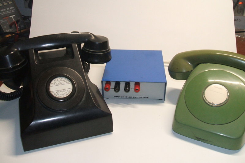
Connect your vintage CB phones together with this simple exchange. Shown here are a 300 series and 800 series types of phone.
Connect your vintage CB phones together with this simple exchange.
Shown here are a 300 series and 800 series types of phone.
When a simple point to point telephone is required, magneto telephones are the first choice. No exchange or interface unit is required. The hand generator in each phone can ring the bell in the other directly. As magneto telephones are local battery, there is no requirement for a DC supply for the line between the phones.
The unit described here allows central battery telephones to be used for the same purpose; i.e., a simple point to point intercom. As manual telephone exchanges are no longer extant, except in museums, about the only thing that CB telephones can be used for, in the modern day, is as an extenstion on an automatic line, to take incoming calls. It should be noted that automatic (dial) telephones are identical to CB types except for the dial connections. In fact, the same chassis is used in both types, with the loop disconnect contacts in the CB version bridged out. It is of course possible to use an automatic telephone on a CB exchange, but the dial is not functional.
Because of the simplicity of the circuit,
certain types of telephone equipment will not work. The phones must have
a mechanical bell. Electronic ringers, or opto coupler circuits used in
answering machines, modems, fax machines, etc. will not respond to the
ring current produced by this exchange. However, given that all vintage
CB telephones do use a mechanical bell, this is not seen as a limitation.
The most common types of CB telephone in Australia are the series 300,
400, and 800 types. There is no reason the circuit wouldn't work with British
700 series and U.S. 500 series types, among others. It has also been tested
with Ericofons, but the ringing buzz is slightly subdued compared to that
from a normal exchange.
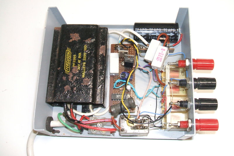
I built this unit in the late 1980's and
it was used in a large house that I then lived in.
Design.
The exchange operates entirely off 40-50V
DC. This could come from batteries, since there is no drain with both phones
on-hook. Here, a 32V transformer provides the supply via a half wave rectifier.
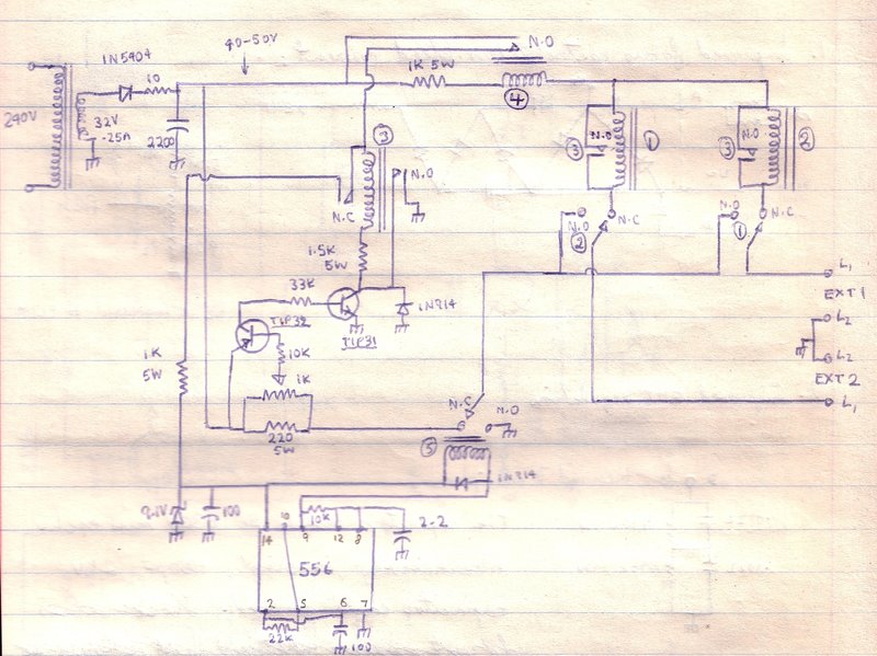
The circuit comprises three sections; 1)
the speech circuit, 2) the ring circuit, and 3) the off-hook-when-answered
detector circuit.
When the phones are both off hook, they
are directly connected to each other, with the RLA4 coil and 1K 5W resistor
providing the necessary impedance to allow the speech voltage to be developed
across the line. There is no DC isolation between the phones when they
are both off-hook and in use.
All the relays are 9-12V types, with a coil current of around 30mA. RLA1 and RLA2 are SPDT types. The line current is set to around 25-35mA by means of the 1K 5W resistor and RLA4's coil resistance. Higher current can be damaging to the carbon transmitters. If RLA4 has sufficient resistance, and a high enough voltage rating, the 1K can be reduced or even eliminated. For example, it should be possible to use a 48V relay with 2000 ohm coil on its own.
RLA3 is a 4PDT type, since it requires three sets of N.O. contacts and one N.C contact. (See 'Modifications' below to eliminate one N.O. contact set). A higher voltage relay can be used here by reducing the 1.5K 5W resistor. RLA4 is SPST with N.O. contacts.
While it is normal in the telephone world to use a positive earth, this unit was built with a negative earth. It makes no difference to telephone operation. Positive earth is used to reduce corrosion effects, and it is easy enough to adapt the circuit if it is felt this is preferable. As the circuit is earthed through the mains supply, it is simple enough to earth the positive rail instead.
How it Works.
Now to describe the sequence of operation:
The two transistor circuit could conceivably be replaced by yet another relay. If such a relay had its coil replacing the 220R resistor, it could be made to detect when the called phone went off-hook. It may be necessary to shunt the coil with an adjustable resistor to set the sensitivity, and a capacitor might be beneficial across the coil also to prevent the ring current actuating the coil.
Alternatively, some simplification could be had with the existing circuit, by replacing the TIP31 with an SCR. The N.O. latching contacts on RLA3 would be made redundant, along with the associated 1N914.
It could be possible to improve the ring
generator with a proper 17Hz 90V inverter circuit. Such a circuit could
consist of a sine wave oscillator, an audio amplifier IC, and a step up
transformer. RLA5 would be deleted. The secondary of the transformer would
connect between the N.O. contacts of RLA1 and RLA2, and where the N.C.
contact of RLA5 was. The ring voltage would therefore be superimposed on
the 50V DC supply.
The 556 could then be replaced with a
555, since it is only required to provide the ring cadence. The 555 output
would switch the 17Hz oscillator. Some thought would have to be given towards
the transformer and the DC supply to its driver.
Of course, such a modification will increase
the complexity, and will be getting away from the present simple minimalist
design.
DC isolation between the phones is actually
desirable, because it prevents one phone sucking out all the current, depriving
the other, if one phone should draw more current. This is not a problem
with the stadard 300/400/800 types of phone, but it can be problematic
when an exotic phone is used.
To improve current sharing, the coils
of RLA1 and RLA2 could each have 1.8K-2.2K resistors in series with them,
and the 1K in series with RLA4's coil deleted. A non polarised capacitor
of at least 3uF would need to be connected between the N.C. terminals of
RLA1 and RLA2. This is required to maintain the AC speech path between
the two phones, since too much audio voltage would otherwise be lost across
the 2.2K resistors.