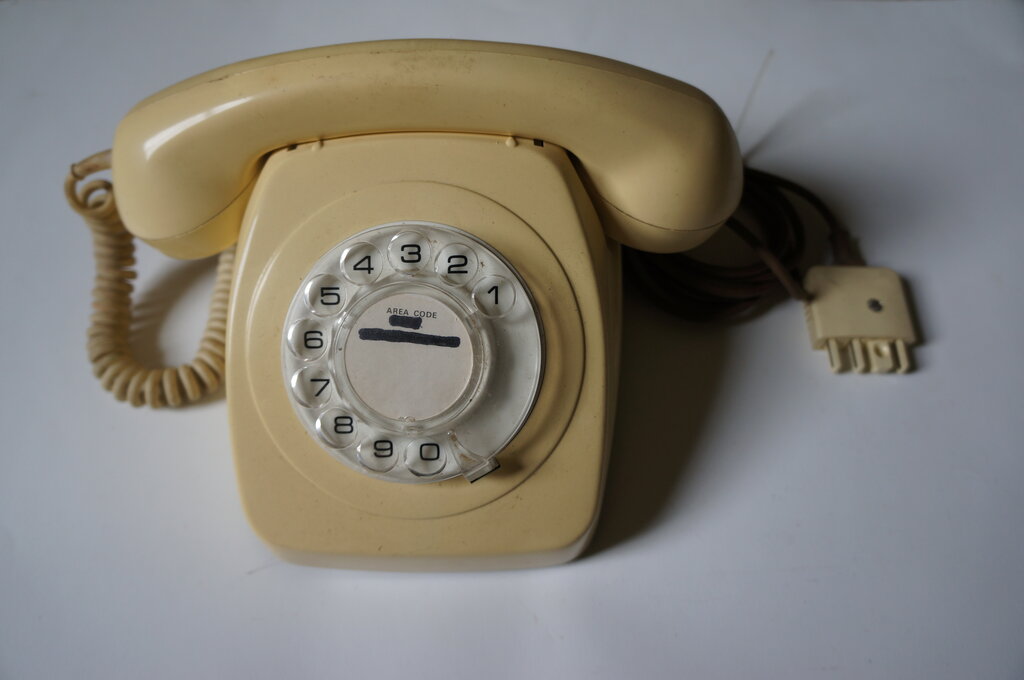
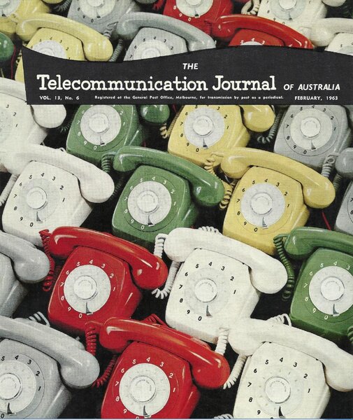
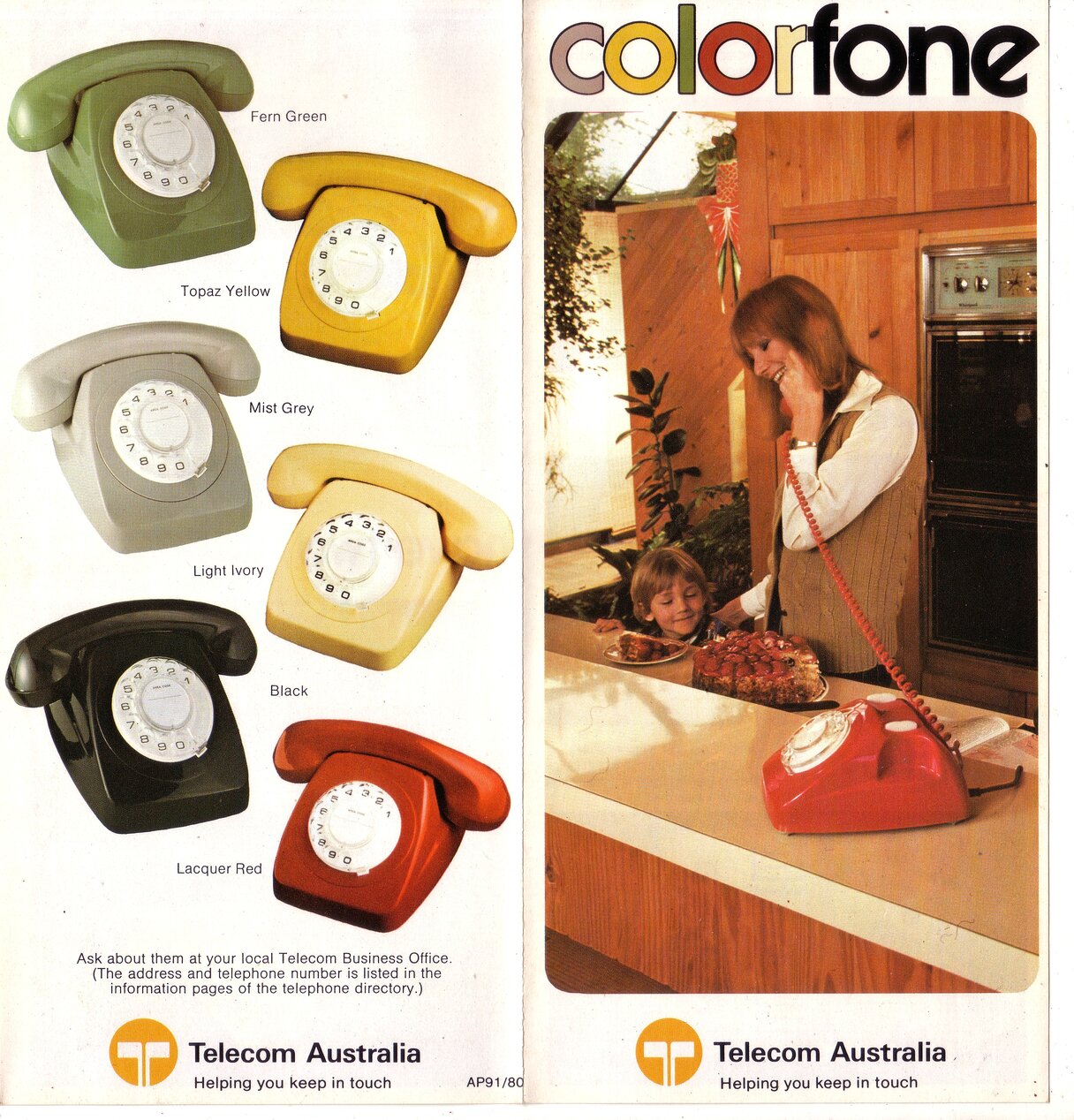
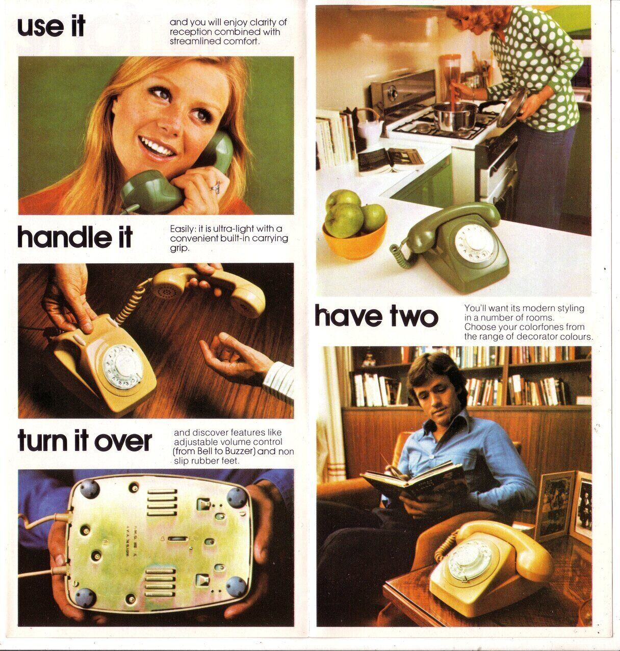
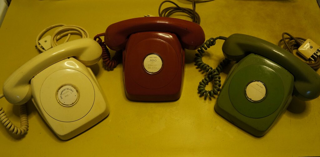
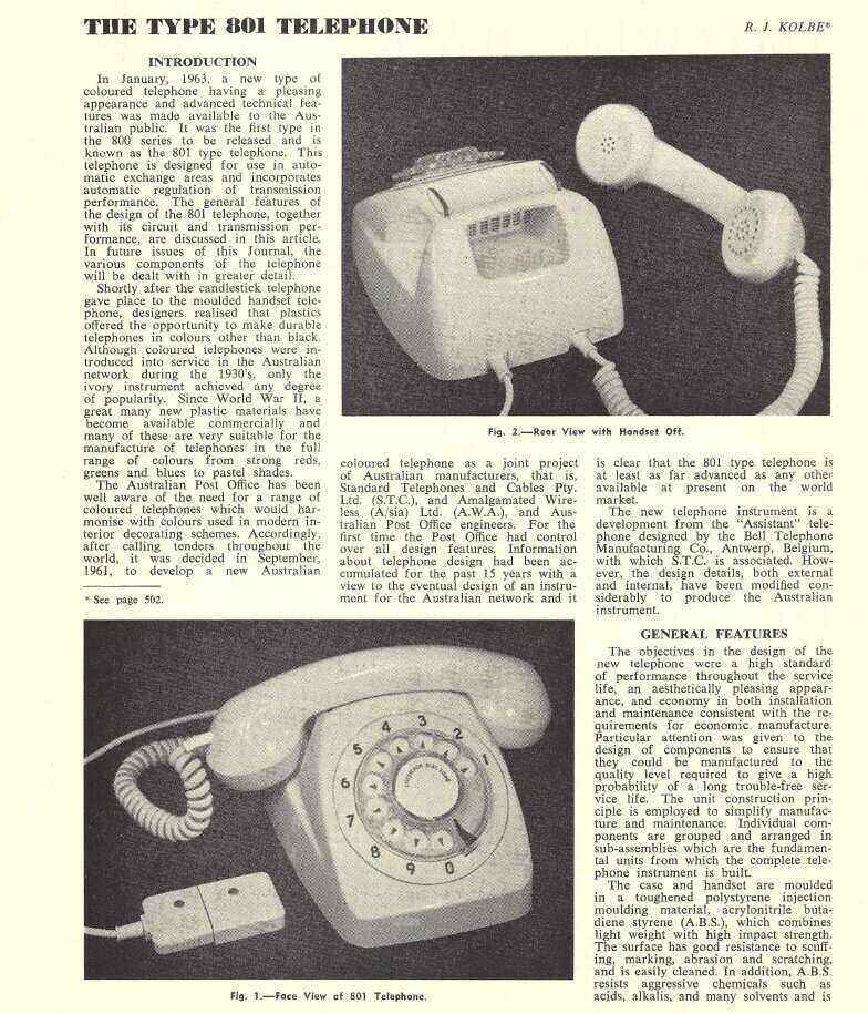
The Series 800 phone was released in Australia in 1963 and was issued until the mid 1980's. It was a replacement for the existing bakelite series 300 and 400 phones which had been standard issue for many years. The external design of the 800 was taken from a telephone used in Belgium, but the internal design is entirely Australian. With the casing made of plastic, it was possible to produce the phone in various colours at no extra cost. The PMG, and later, Telecom, advertised it as the "Colorfone". The 800 was only ever made for automatic and C.B. working. There was never a 'modern' telephone for magneto services, with existing instruments retained and reconditioned right up until the end of manual exchanges.
Electrically, it had several improvements
over the bakelite 300/400 series instruments. Automatic current regulation
was incorporated so that the phone could be used on long and short lines
with no modification. Prior to this, it was necessary to connect a 330
ohm resistor in series with the phone on short lines to keep transmitter
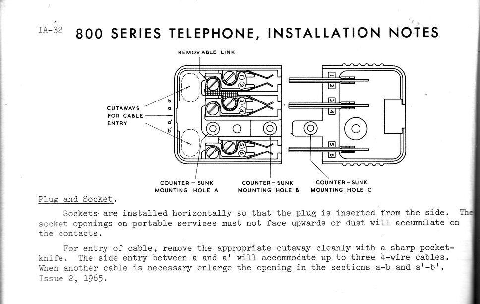
current to a safe level. A six pin plug (type 603) and socket (type 610)
was used with the new design. This allowed greater flexibility with configuring
the phone to work with different wiring plans, compared to the previous
four pin plug and socket - which was only used with portable services.
Until now, the 300/400 series phones were connected permanently to the
line via a 20/4 terminal block, unless a portable service was installed.
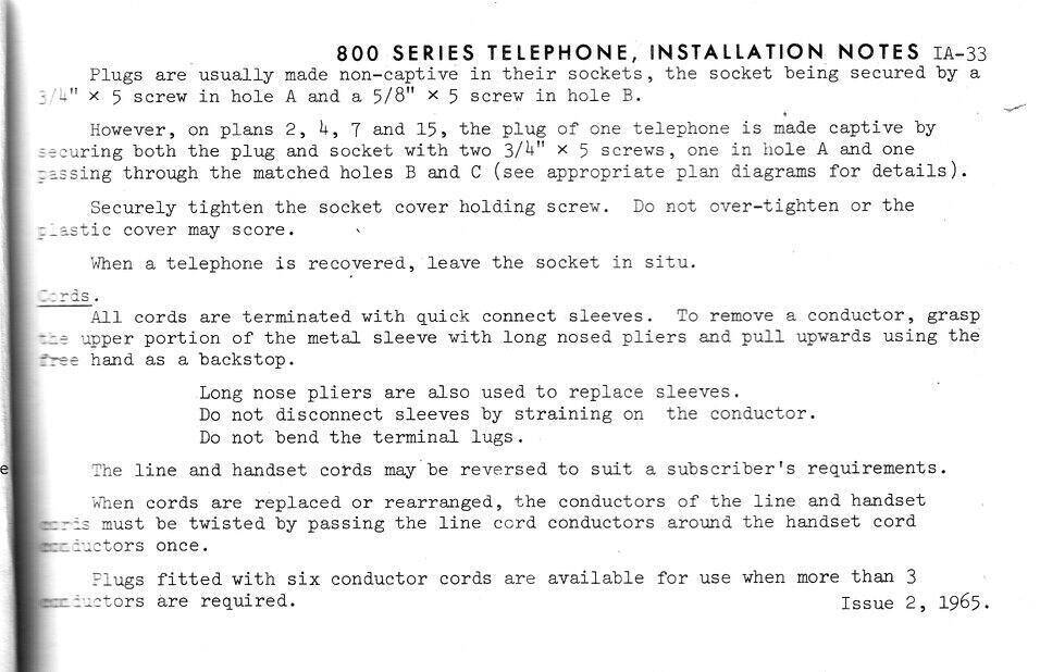
With the introduction of the series 800,
all phones would be connected via plug and socket. If for some reason the
connection needed to be made permanent, the design allowed for the plug
to be made 'captive'.
Previously, the 300/400 series used screw
terminals with links to configure the phone for its intended wiring plan.
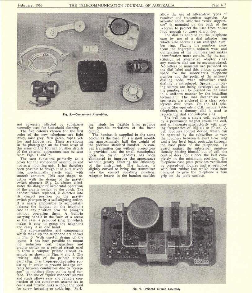
The 800 series was built on a printed circuit board and used miniature
quick connect lugs.
The plugs and sockets, patented by AWA,
were made by Transpro (TP), and the cords were made by Bly. Until 1975,
the line cords were three conductor as standard, and of the same colour
as the phone. From 1975, cords were 'teak' coloured and four conductor.
Six conductor cords were available when required.
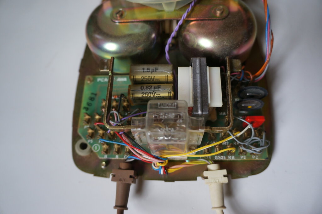
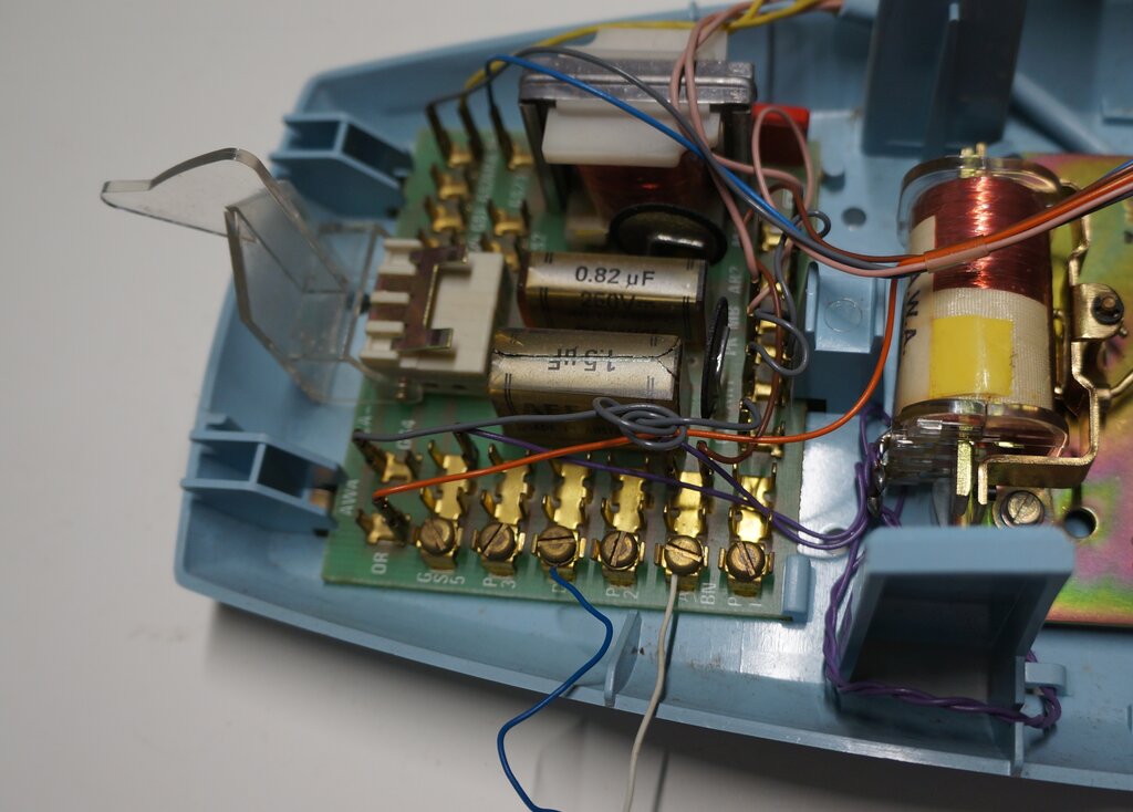
Internal wiring. Connections are made with quick connect lugs onto
a PCB.
Several dials were used, initially made
by STC, and finally by AWA. The handset cord anchorage was improved in
later instruments. Commonly seen would be an 800 series phone with the
individual handset conductors exposed when the clamp lost its grip. This
was just a simple clamp relying on friction against the cord grommet, and
was not very effective. Later design provided a special moulded grommet
which engaged in slots in the clamp.
The transmitter was the same No. 13 type
used previously, but now fitted with quick connect terminals. Towards the
end of the 800 series, an NEC manufactured solid state replacement had
been developed, using a condenser microphone. The receiver was the 4T rocking
armature type, previously used with the 400 series handset. However, a
back to back diode assembly was now wired across it to prevent loud acoustic
shock.
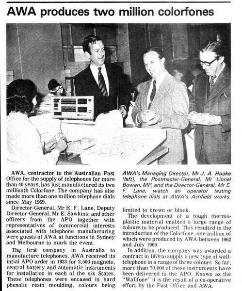
From Electronics Australia, October 1973. Two million 800 series
phones had been produced in 10 years.
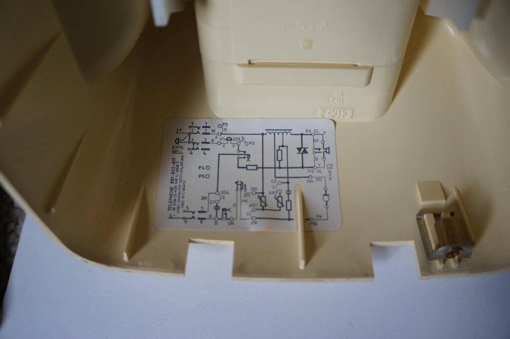
Circuit label inside phone casing. Note that this is a later model
(from 1982) and has a four conductor line cord.
There were many wiring plans and configuration
for the 800 series phone. There were several types of parallel working,
instruments fitted with recall buttons, hearing aid amplifiers, multi line
variants, and so on.
In this article, we'll concentrate on
the typical domestic instrument used on its own. For parallel working,
some description is given here.
Getting your 800 Series Phone Working.
Since the days of the exchange line coming
into a house are now on their way out, most users of the 800 phone will
be using it on a VOIP service, from a modem or ATA (Analog Telephone Adaptor).
In Australia this is typically provided by the NBN. This is where a lot
of owners of 800 series phones have encountered problems.
There are two things to deal with. The
most obvious is that VOIP services do not work with decadic dialling. They
are DTMF only. That means the loop disconnect pulses generated by a mechanical
telephone dial are ignored, and it's only possible to accept incoming calls.
Therefore, an adaptor is required which
converts the dial pulses to DTMF. The best known of these is the Dialgizmo,
which is described further here.
With a Dialgizmo installed between the
phone and the modem or ATA, it's now possible to dial out. The Dialgizmo
counts the dial pulses and generates the required tones. No modifications
are required to the phone, and for all practical purposes, what comes out
of the Dialgizmo simulates an old fashioned automatic exchange line.
The Phone Doesn't Ring!
So far so good, but a very common complaint
when attempting to use an 800 series phone is that it no longer rings on
incoming calls. To see why this is, and what to do about it, we need to
look at the circuit of the phone.
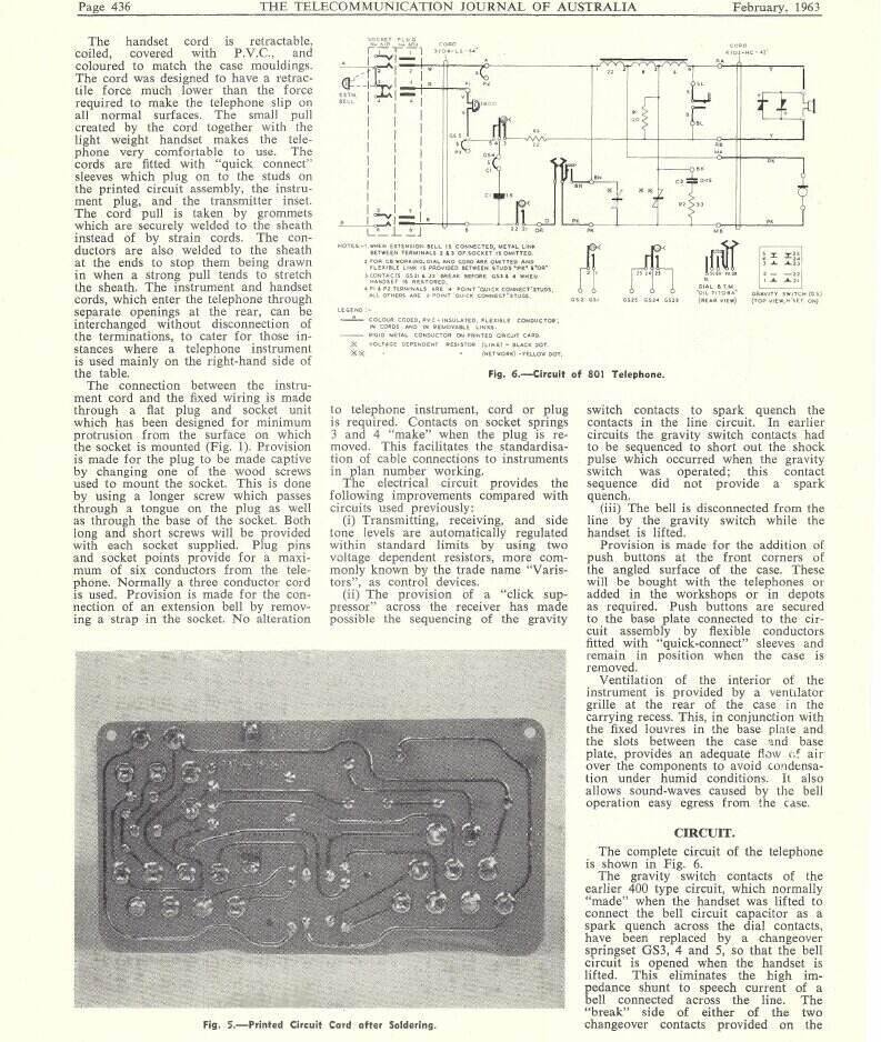
Looking at the wiring plan below, we can
see there's a three conductor cord:
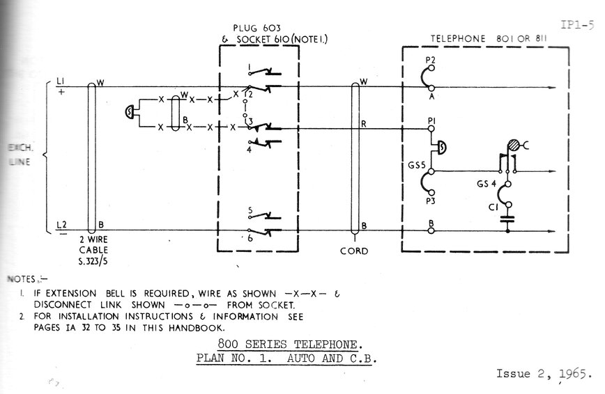
Plan No.1. Basic exchange line to single instrument wiring plan.
Where a four conductor cord is fitted, the black wire connects to GS4 and
pin 5 of the plug.
By default, there is a link in the socket between pins 2 and 3. We can see that ring current flows from pin 2, through the link to pin 3, then to the bell via the red wire to terminal P1 inside the phone. From the bell, current flows through the gravity switch contacts (closed with the handset on hook), through terminal C1 to the DC blocking capacitor, and out via the blue wire connected to terminal B and thence to pin 6 of the socket. Where an extension bell is fitted, the link between pins 2 and 3 is removed, and the bell connected in its place. Connected thus, the extension bell is in series with the telephone bell.
The problem of the phone not ringing occurs
because of two possibilities; 1) the phone was previously configured for
parallel working, or 2), there is no connection between pins 2 and 3 of
the socket.
If the phone has been set up for parallel
working, it will either be as the first phone, or a second phone. For parallel
working, one phone (the first phone) provides bell current to the second
(and/or third) phone.
In the case of the first phone, the link
between A and P2 will be moved from A to P1. The red wire previously connected
to P1 will now connect to GS5. The link between pins 2 and 3 in the socket
is removed, and the red wire is connected to pin 3.
If this phone happens to be plugged into
a socket where the link exists between pins 2 and 3, the bell will be short
circuited and the phone will not ring. Aside from that, the DC blocking
capacitor will be connected directly across the line, resulting in muffled
speech.
If the phone was configured for parallel working, but as a second phone, the link between C1 and GS4 will be removed. A and P1 will be linked, and the red wire will connect to GS4. Again, this phone will not ring when plugged into a socket wired for a single phone, whether or not pins 2 and 3 of the socket are linked. With the DC blocking capacitor out of circuit, no current can flow through the bell. See here for more on parallel operation.
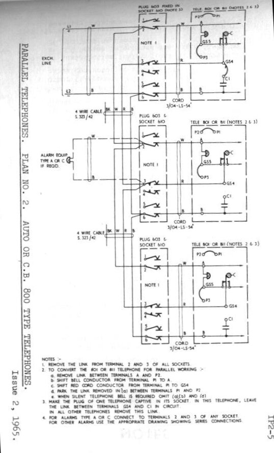
Plan No.2. Wiring for parallel connection of 800 series phones.
Note the different configuration for the first and subsequent phones.
So, the first thing to do when using a single 800 series phone is to ensure the internal configuration is as per the label inside the casing (or Plan No.1). The phone will then suit a 'normal' two wire service, as a single phone.
RJ11 to 610 adaptors.
Invariably, with a modem/ATA/Dialgizmo,
or any other modern phone accessory, RJ11 connectors become involved. This
is the U.S. standard "modular" connector which has also been adopted in
Australia in recent years. So, to use your 800 series phone, you'll need
an adaptor. And, this is where problems occur.
Most RJ11 to 610 adaptors assume a modern electronic phone will be used, and only pins 2 and 6 will be connected in the 610 socket for the incoming line. However, if you have closely observed the previous wiring diagrams, it will be seen that the 800 series phone also has a connection to pin 3, which feeds the bell. Not surprisingly, without this connection, the bell won't ring.
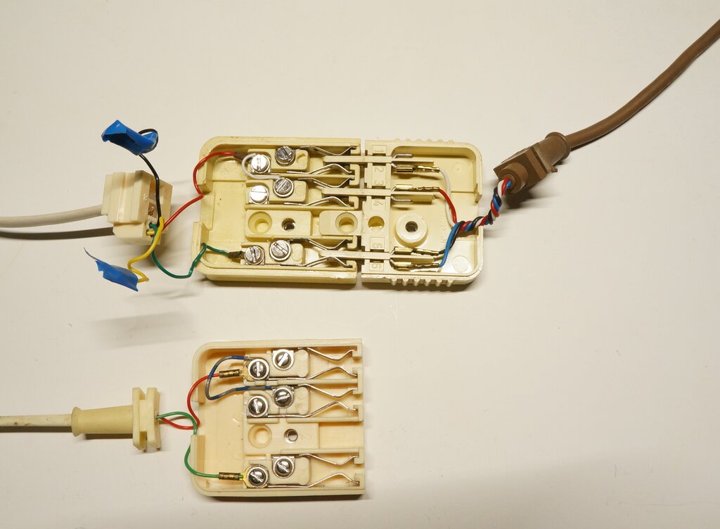
Adaptors modified. Note the wire added between pins 2 and 3. Phone
will now ring.
All that needs to be done is to connect
a link between terminals 2 and 3 of the socket, as shown in the photo above
(white wire in top adaptor, blue/grey wire in bottom adaptor). If there
are yellow and black wires present coming from the RJ connection, these
should be disconnected, as shown with the adaptor in the top of the photo.
Some 610 sockets used with such adaptors
are sometimes missing the pins at terminals 3 and 4. If so, it's possible
to lift out pin 1 and move it to the pin 3 position. Ultimately, the socket
should be configured as per the photo.
Later series 800 phones with the brown ('teakwood') line cord have a black wire connected to pin 5 of the plug. A few phones will also have green and orange wires. None of these are used in this application.
Alternatively, if it's desired to configure an 800 series phone for genuine two wire working, this can be done by opening the phone and moving some connections around on the circuit board. Move the violet bell wire from P1 to A, and connect the red wire of the line cord to P2 (an unused terminal). In this way, the phone will work in any 610 socket as long as the line is connected to pins 2 and 6. No connection to pin 3 is required.
If the phone has a recall button, it's highly likely that the red wire will connect to pin 1. In this case the red wire is for the recall button, and the phone has been reconfigured to do away with the pin 3 connection. The adaptor won't need modification in this instance.
Some 300 and 400 series phones were fitted with 603 plugs, and the wiring patterns follow that of the 800, although of course with different terminal designations inside the phone.
Note that while the Ericofon also uses the same plugs and sockets as the 800 series, the configuration is again quite different. See here for further information on using the Ericofon.
Intercom for Series 800 Phones.
If you haven't got an exchange line or
VOIP service, you can use a pair of series 800 phones as a very effective
intercom.
Central Battery Series 800.
Series 800 Central Battery.
The CB version of the 800 is of course internally the same as the automatic version, except that the dial is omitted and the loop disconnect contacts are jumpered. It can be used to take incoming calls in the normal way, and in this regard a Dialgizmo is not required. As previously described, the socket connections and internal jumpers need to be correct for the bell to ring. CB telephones can also be connected together to form an intercom.
An interesting project would be a voice recognition circuit connected across the line, so that the phone could be used to make outgoing calls to an automatic line, by reciting the required number, as one does with a manual exchange. In other words, an 'electronic' operator. When the handset is lifted, a synthesised voice would say, "number please". Then the user says the required digits, which the voice recognition circuit converts to DTMF tones.
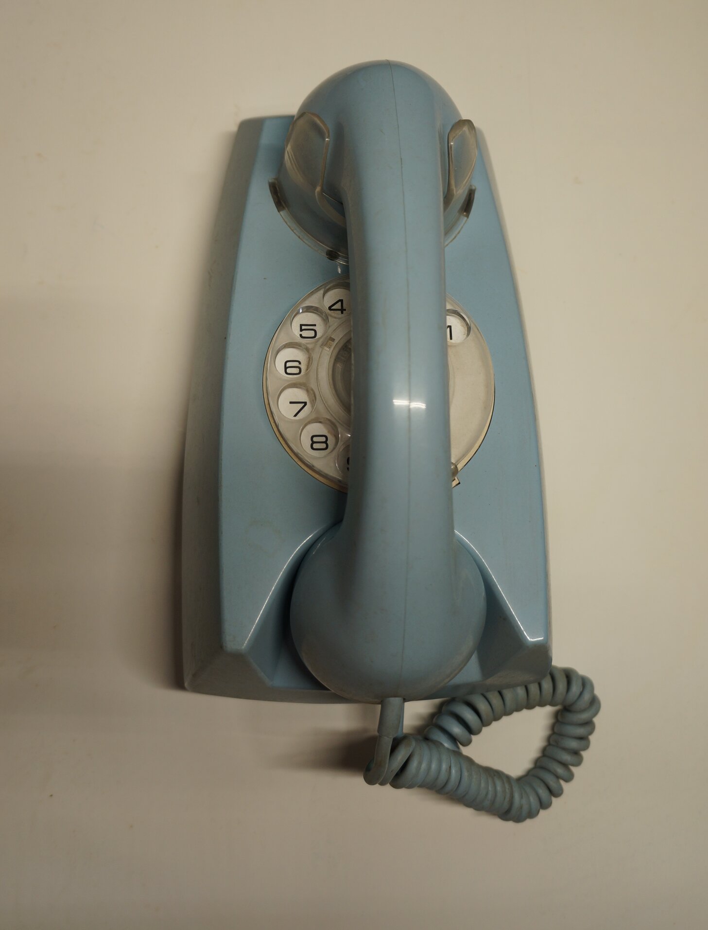
891 Wallfone.
The wall version of the 800 series was
introduced in 1970 as the 891 "Wallfone". It is electrically the same as
the table models, but has different terminations in view of being permanently
connected to the line.
The line conductors are connected directly
to screw terminals on the PCB.
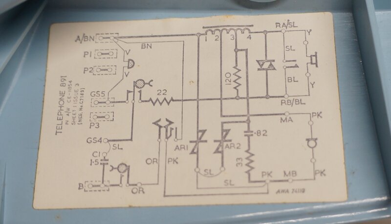
Circuit diagram of the 891.
Exchange line connected for single working.
For a single phone connected to the exchange
(or VOIP adaptor), connect to terminals A (white/L1) and B (blue/L2). If
using a U.S. colour coded cable, red to A, and green to B.
Unlike the table model, there is no extension
bell link to be bridged.
Parallel connection is electrically the
same as the 800 series. Where the 891 is the first phone, the bell feed
(red wire) can be connected to P3 which in turn connects to GS4 via a link
which has to be provided and installed. If you're lucky a spare link will
be stored on one of the unused terminals inside the phone.
Where the 891 is the second phone on a
parallel service, remove link SL from between C1 and GS4, and use it to
connect P3 to GS4. The red wire connects to P3.
.jpg)
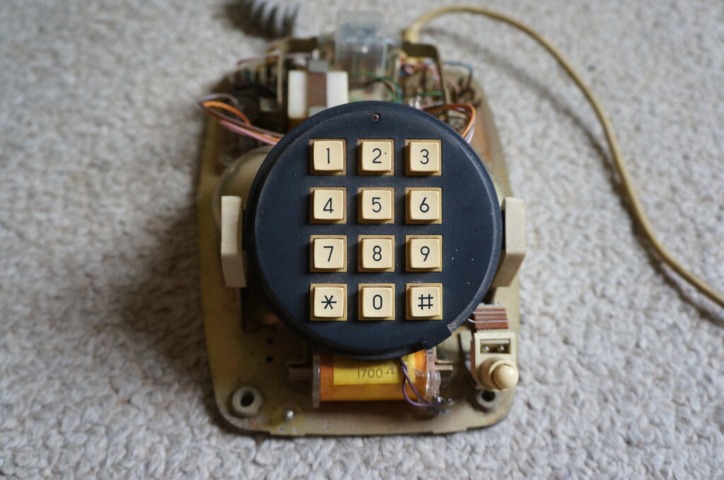
This example has the DSE pushbutton dialler fitted.
Occasionally, chrome plated series 800 phones appear. These were never officially issued, and it seems most were done as a 'foreign order' in the PMG/Telecom workshops. The example shown here was very kindly supplied by a fellow HRSA member.
Inside the phone. It's an STC chassis from 1973.
It does appear this phone was originally of the "Topaz Yellow" colour, judging by the line cord, and the plastic visible under a few small chips on the chrome plating. The handset cord has been replaced by a later grey type which is a more suitable match for the chrome. This is dated 1983, and is a likely time that the phone was plated and modified. Note that this phone is fitted with a recall button, which suggests it was installed in a commercial situation.
Safety Concerns.
I had seen mention that Telecom wouldn't
actually approve these chrome plated phones because the plating is conductive.
The chances of a shock hazard are greatly increased. I tested this, and
indeed, there was continuity from the chassis to the handset resting in
the cradle. One might be hesitant to use this phone during a storm, particularly
if it was fed from an aerial service. Holding a conductive handset, and
against one's ear, where the only isolation is the thin insulation of the
wires, is something to contemplate.
.jpg)
Conductive path exists from the chassis screws to the outside of
the casing.
.jpg)
Plating extends to inside the handset and transmitter and receiver
cups.
We can see that the only isolation between the phone line and the user's body is whatever insulation exists inside the 4T receiver.
The Dick Smith Push Button Dialler.
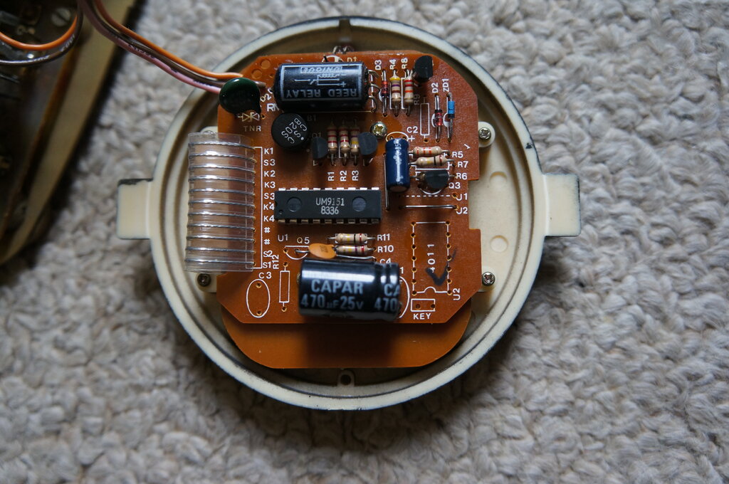
Dialler is decadic only and uses a UM9151 IC. This one appears to
be from 1983.
Quite a number of series 800 phones were retro fitted with a push button dialler, which was sold by Dick Smith Electronics. Whilst Telecom did issue a push button 800, the rental was more than the standard dial version.
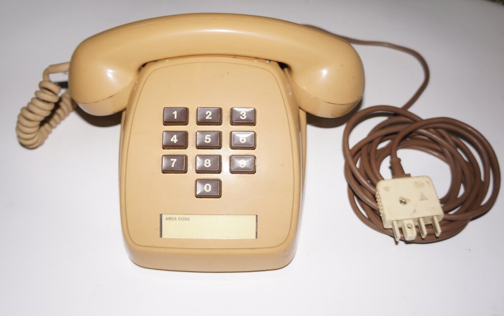
Series 800 push button phone. Rental charges were higher than the
standard dial phone.
The enterprising genius of Dick Smith had
a drop in equivalent produced, so one could have push button dialling,
but without paying extra rental. The dialler itself is based around a UM9151
IC. A reed relay performs the loop disconnect for dialling. There is a
LED at the top of the dial which illuminates when the phone is off hook.
It presumably shows the presence of line current, since it flashes in time
with dialling. Since this dialler is decadic only, it's necessary to use
a Dialgizmo where DTMF is required. This particular dialler has a black
facing, which is the first I've seen. All the others have been cream. Possibly
it had been painted for this specific installation.
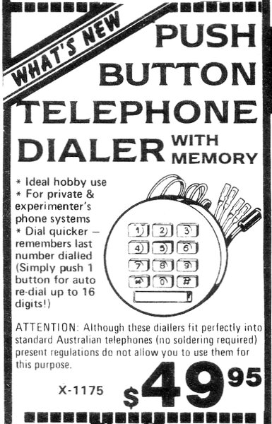
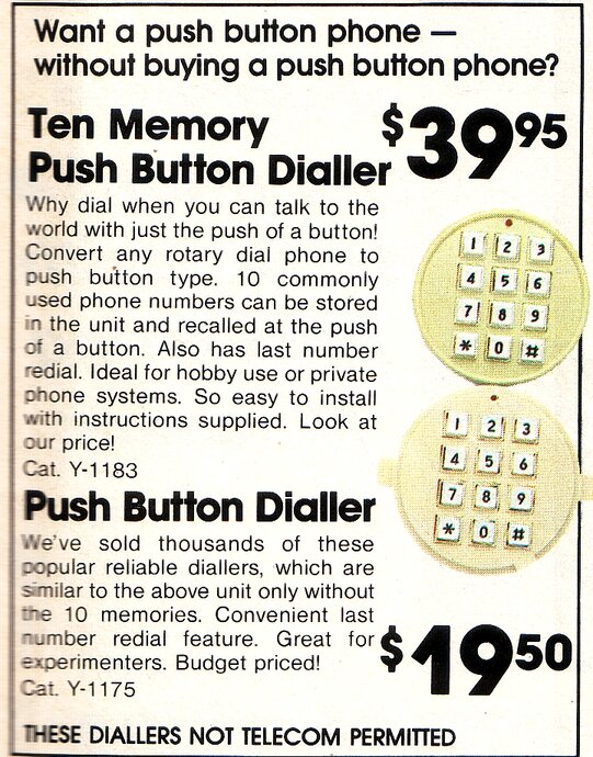
Advertisement in Electronics Australia, June 1979 (left), and from
the 1984 catalog (right).
The diallers first appeared in June 1979,
and were last shown in the 1984 catalog. Not surprisingly, they were not
Telecom permitted. In fact, Telecom was horrified at the idea of people
taking apart their phones, and replacing parts inside them. This was the
era when Telecom was very strict about what could be connected, and used
with their service. Essentially, the only instruments allowed were those
supplied by Telecom, or which had been approved from other suppliers, and
installed by Telecom.
Dick Smith caused much controversy around
this time, because they started importing not only these diallers, but
a range of phones (push button and cordless), and answering machines, from
Hong Kong. The reality was, Telecom couldn't offer anything like this range.
You were basically limited to the 800 series table and wall phones, or
the Ericofon. The only push button phone available was the expensive series
800 table phone. All of these were available as rentals only.
Telecom naturally, didn't like this 'competition', but couldn't do anything about it. DSE's disclaimer was simply that they were not Telecom permitted, and should only be used for 'private networks' or 'experimental' use. Of course, we all know that's not what happened, and these telephones and accessories were extremely popular. It was this proliferation of more modern looking and functional phones, which you could buy outright, that showed up how conservative Telecom was. It's understandable; being a government organisation, set in their ways with no competition. As a result, Telecom was pressured to introduce a range of feature phones by the mid 1980's. Then deregulation came in, and it was now officially permitted to buy your own phone, and cease paying rental for the Telecom supplied instrument.