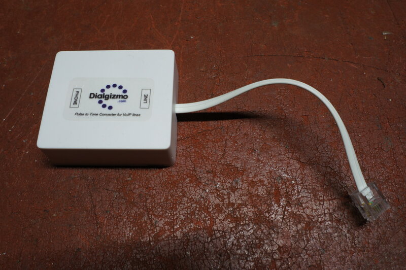
Entire unit is built into an RJ11 wall socket.
To many people, connecting to the NBN infers
giving up their previously used phone(s), whether DTMF (tone dialling),
or decadic (rotary/pulse/loop-disconnect) dialling. This, in actual fact,
is not true, and this article explains how I was able to restore full operation
of all my phones.
But first, for non Australian readers,
what is the NBN? It's a national fibre optic broadband system (National
Broadband Network) that is intended to replace the existing copper telephone
cabling which also supports the ADSL internet. There is so much written
about it, I won't go into further detail, but the important point is that
once fully implemented, the existing copper cable from the exchange to
the house will no longer be available. In other words, one is forced to
subscribe to the NBN, with no choice to retain the existing exchange line.
The NBN reaches the consumer in a number
of different ways, depending on the technology available at the time, cost,
and existing infrastructure. Typically, there is FTTN - Fibre To The Node,
FTTC - Fibre To The Curb, FTTP - Fibre To The Premises, and HFC - Hybrid
Fibre Coaxial. The initial plan was for all premises to be fed with fibre
optic cable (FTTP), but politics (cost and speed of installation) caused
the more outdated methods to be implemented instead, for most installations.
As a result, the NBN is the laughing stock of Australia and is seen as
already outdated. Problems abound with dissatisfied customers; reports
of which are readily available in any relevant forum, social media, etc.
Telephones and the NBN.
Knowing I would have to face up to it
one day, I had already devised plans of how I'd deal with the loss of my
exchange line, and how to keep all my existing telephones working. The
NBN service provides a telephone service as well as the internet. It uses
VOIP (Voice Over Internet Protocol) for the telephone; something which
has been around for some years now. Effectively, telephone communication
is done over the internet, and as such, VOIP phones have an IP address
etc. You can use a conventional domestic phone with VOIP too, by use of
an ATA (Analog Telephone Adaptor). This small box is set up the same way
as a VOIP phone, but provides an output which simulates a normal exchange
line; e.g. 50V line and 75V ring voltages. Outgoing calls are made in the
normal way, and the phone rings normally on incoming calls.
The NBN modems supplied by the ISP actually
work on VDSL, and typically, as well as providing a 4 port router for the
internet, also have an inbuilt ATA which provides an analog telephone output.
At this point, one may plug in a phone to this socket, and a computer to
one of the LAN sockets, and everything will function as it did before.
However, a major stumbling block is the
ATA built into the modems. These only respond to DTMF dialling. If you
connect a decadic dialling phone, the ATA will ignore the dial pulses and
it is impossible to make outgoing calls. The phone still rings on incoming
calls, and the speech circuits function normally. There are a few stand
alone ATA's that do work with decadic dialling, and if the VOIP settings
are known, one could be used instead. Some ISP's, such as iinet, will not
reveal the VOIP settings, so one is forced to use their modem for the phone.
What is the difference between DTMF and
decadic dialling? DTMF is Dual Tone Multiple Frequency, and each time one
of the keypad buttons is pressed, two tones are generated. The tone frequencies
were carefully chosen to be outside those used in normal speech. The system
was developed in the 1960's in the U.S. but did not become commonplace
in Australia until the late 1980's. Tone decoders in the exchange determine
the digit transmitted. Decadic dialling has been around since the first
automatic exchanges at the beginning of the 20th century. It transmits
one of ten pulses by repeatedly interrupting the line current. It is also
known as loop-disconnect, or sometimes pulse dialling. 'Rotary dialling'
is a term used by less technical people, since it relates to a mechanical
dial, but it is not entirely correct, since there are many push button
diallers that are decadic dialling only. The advantages of DTMF apart from
being faster to dial, is that dialling information can be transmitted where
it is difficult to retain the DC component, such as over a radio link.
The Dialgizmo and DTMF to Decadic conversion.
Entire unit is built into an RJ11 wall socket.
Obviously, to use a decadic dialling phone
on the NBN or any other VOIP network, a decadic to DTMF converter is required.
While I have contemplated designing and building one myself, I had a look
at what is already available. There are two different methods used with
commercially available devices. One is the Rotatone
or
similar device, which connects directly to the telephone dial inside the
phone, and produces the DTMF signal. In effect, the telephone becomes a
DTMF type despite the mechanical dial. There are also plans on the internet
for homemade devices based around an Arduino or other microprocessors,
which operate the same way.
The other method is to convert the decadic
pulses to DTMF externally to the phone. This is used by the Dialgizmo
and a similar Chinese device available from eBay.
Where multiple phones are in use, each
would require its own Rotatone, whereas with a true decadic to DTMF converter,
only one is required to feed all the phones. Furthermore, installation
of a Rotatone requires modifying the phone and detracts from originality.
The line is still DTMF only.
In my situation, with eight phones in
use, the choice was obvious and a Dialgizmo was purchased and tested. The
idea was to connect it at the phone output of the modem, and thence into
the phone wiring of the house. This would restore the ability of using
decadic dialling on any phone as previously.
A quick look at the Dialgizmo.
The unit is tiny. It's actually built
into an RJ11 wall mounted socket and has a short lead to plug into the
DTMF line.
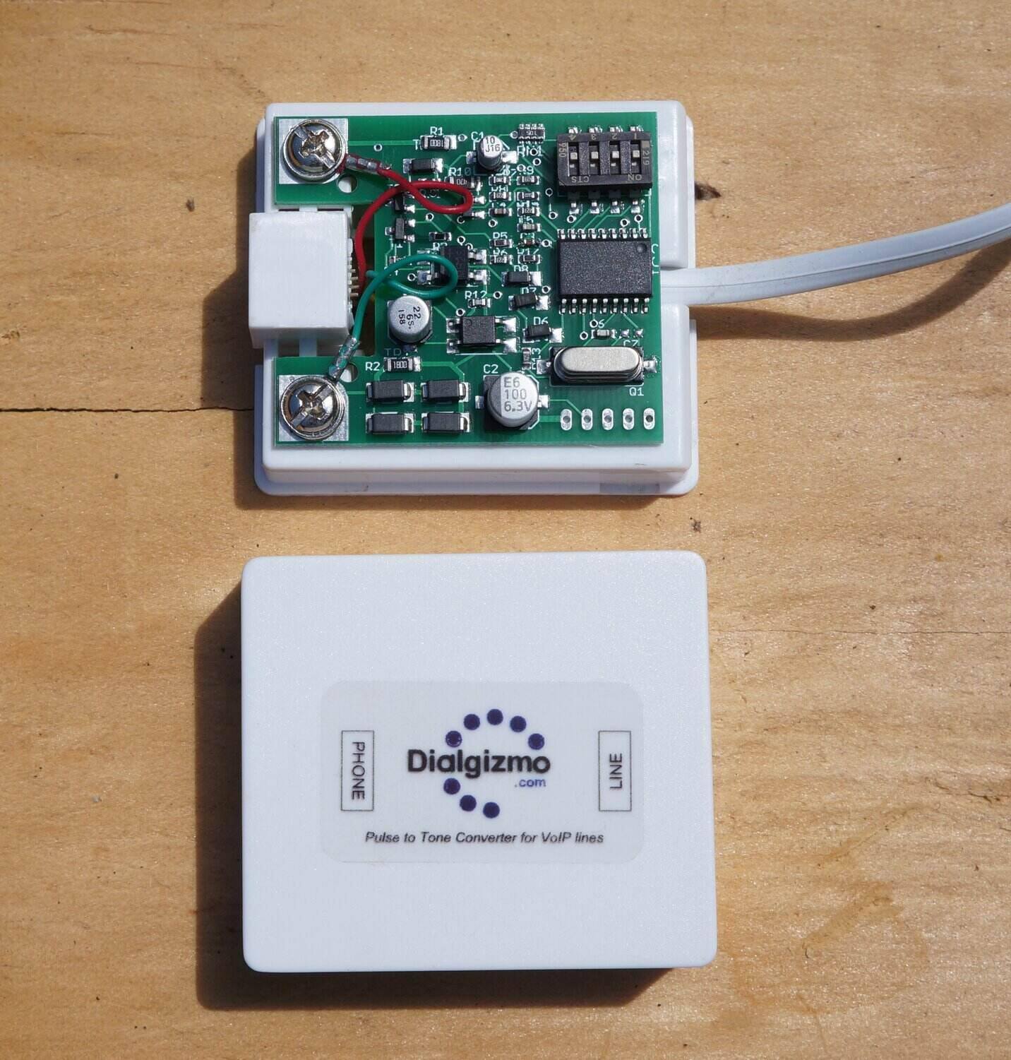
Inside the Dialgizmo. Note the configuration switches.
Inside is the expected microprocessor and
crystal to count the pulses and generate the tones. There's also a set
of DIP switches to set the configuration for different dials and to enable
or disable some of the other features. Not all dials in use around the
world have the numerals from 0 to 1 in a clockwise direction. For example,
NZ dials are the reverse. The dip switches allow for these differences.
Conveniently, it's also possible to dial # and * by holding 1 or 2 against
the dial stop for two seconds. There is also a last number redial, and
it's also possible to store numbers. Unless one is always using these latter
features, it would be to easy forget the sequence since it is not intuitive.
In any case, they didn't exist before so I do not feel I am missing out
on anything.
The Dialgizmo certainly works, and works
well!
An Important Note about the Dialgizmo.
The Dialgizmo requires a certain minimum
line voltage to function when the phone is off hook. The line voltage appearing
across the Dialgizmo is a function of the line current and the resistance
of the phone. It appears that the minimum voltage across the phone must
be 2V, or the Dialgizmo will not produce the DTMF tones. The problem may
arise when a modem/ATA is used which provides a lower than normal line
current, and a load with a very low resistance, such as a line isolating
transformer. If this happens, insert a resistor in series with the load;
typically 100R 1W. See the article on the Gold
Phone interface for more information.
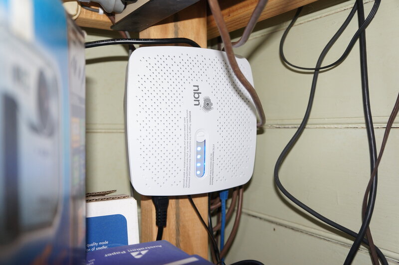
NBN Connection Device.
The NCD feeds 60V into the copper pair
out to the street pit and powers the optic fibre transceiver installed
therein. Disadvantage - the NCD operation adds to my power bill, and unless
I use a UPS or power it from my solar DC system, it stops working during
a power failure.
From the NCD comes a VDSL signal which
then feeds the modem. I was supplied with a TP Link Archer VR1600v. It
has four LAN ports as well as both 2.4GHz and 5GHz Wi-Fi.
I can only assume it's for political reasons
the NCD and modem are separate boxes. There is no technical reason they
could not be in the one unit, which would be a lot tidier.
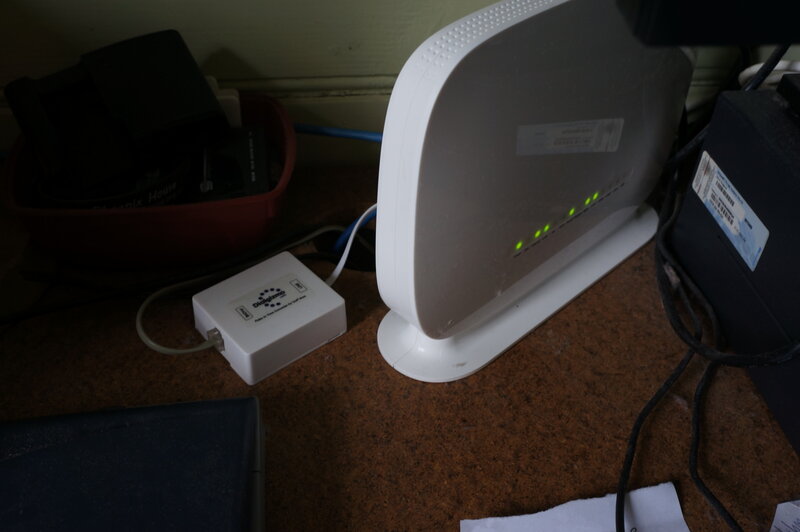
Modem and Dialgizmo.
The cut-over is an interesting process.
While I was away and did not see it, it seems the optic fibre transceiver
was installed in the pit on a Saturday. On the Sunday morning I received
an SMS to say I could connect the NCD and modem. The existing phone and
ADSL were still working normally. The warning is given that once the NCD
is connected, the exchange line is permanently disabled. My knowledge of
this technology is not great, but my guess is that there are fuses in the
optic fibre transceiver, between the exchange line and my house line from
the pit, and once the NCD is plugged in, the 60V blows the fuses, thus
disconnecting the exchange, and powering up the transceiver. So, cut-over
is done by the consumer at their convenience.
Anyway, as soon as the NCD and modem booted
up, I had full internet and a dial tone. I could make outgoing calls, but
incoming calls had not been enabled until the Tuesday. Temporarily, I was
using an 800 series phone with the Dialgizmo, until I sorted out the rest
of the cabling.
Apart from deletion of my website hosting
by iinet, without warning, it was actually a very easy and straightforward
process.
Phones at the House of Cool386.
Now to the interesting part - how did
I get all my old phones working? I have eight phones in use, and an answering
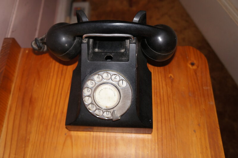
machine. Here's an introduction to them all:
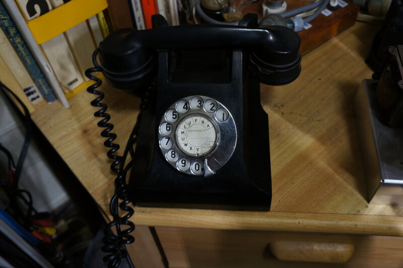
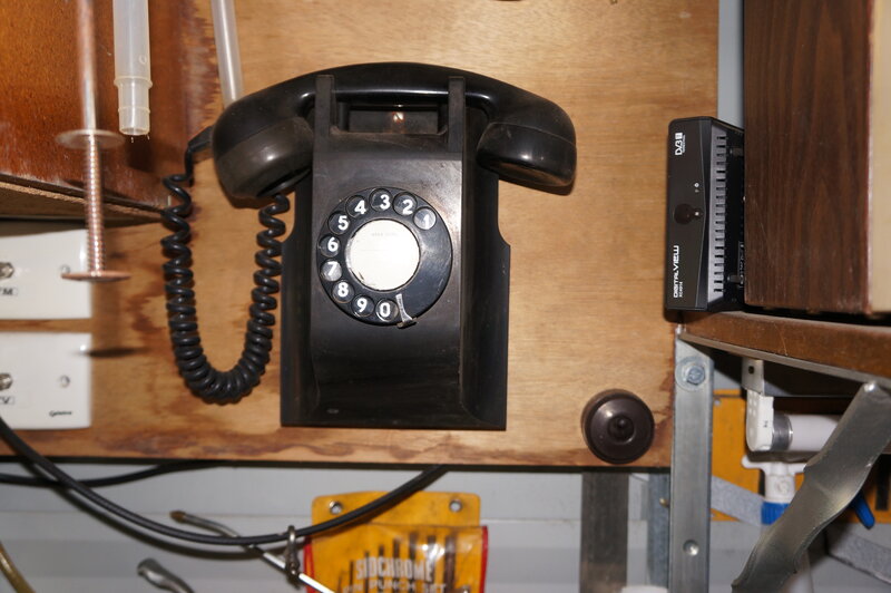
Workshop phone. 332AT. Three wire operation, bell disconnected.
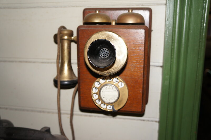
Hall phone. An ersatz 37AW. Three wire operation. Bell capacitor
supplies the other three wire phones.
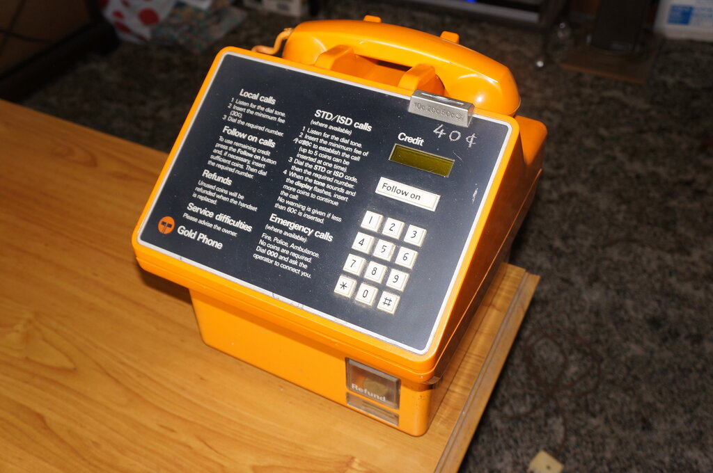
Living room phone. Telecom Gold Phone. Two wire working.
Bedroom phone. 400APKO. Three wire working; bell disconnected.
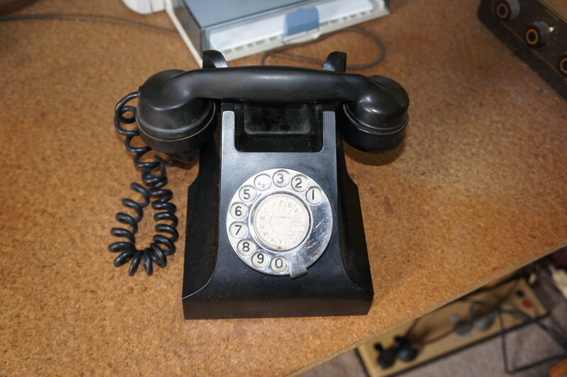
Computer room phone. 332AT. Three wire working; bell disconnected.
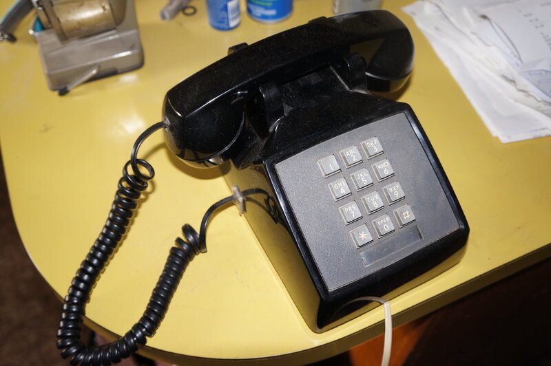
Kitchen phone. DTMF only 2500 from the U.S. Two wire working.
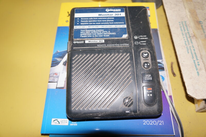
Answering machine.
Garage phone. 400AW. Three wire working; 2.2k in series with bell
to reduce volume.
Shed phone. 891. Three wire working. 4.7k in series with bell to
reduce volume.
Boosting the Ring Current.
Theoretical plans were immediately thought
of and drawn up for a unit to boost the ring current from the modem. Officially,
PMG and Telecom literature stated that a maximum of three bells were allowable.
Modern terminology would say this is an REN of 3, where REN stands for
Ringer
Equivalent
Number.
If this number of bells was increased, there would be no guarantee they
would ring properly due to increased ring current.
In practice, I've never had any problem
with six bells on the line; I've not tried more, and since I'm not far
from the exchange, the line resistance would have little effect.
In my present installation, there are
three bells fed directly from the line, with another two at reduced
power through series resistors, and one opto-coupler in the answering machine.
The main bell in the house is the one in the 237AW in the hall. Since the
gongs are exposed, and it's mounted on a hollow wooden wall, the ring is
very loud. For this reason, all the other three wire phones in the house
have the bells disconnected (and it lightens the ring current).
I was under the impression that the REN
of the modem would probably be only 1 or 2, with the assumption electronic
ringers with their low current would be used, hence my plans for an REN
booster. Such things are commercially available, but cost a ridiculous
amount. Hence, the decision to design my own.
So, just what did we need to ring my system?
I fed an audio oscillator into the line and obtained a normal ring volume
with a 50Vrms sine wave at about 20Hz.
Out of curiosity, I then measured the
output of a stand alone LinkSys ATA and found it provided about 97Vp-p,
or 34Vrms at 25Hz. Thinking it would have a fairly low REN and probably
go into current limiting, I connected it into my phone system and was quite
surprised to find it had no trouble ringing all the phones.
Calculating the actual ring power required,
with a current of 22mA, it came to about 750mW. Surely the modem could
supply that amount of power I thought.
Thus inspired, I tried with the modem,
and likewise all bells rang successfully. I had just saved myself a considerable
amount of work! Evidently, the REN is a conservative rating.
What about the Dialgizmo and ring
current?
The instructions quote an REN of 2. Again,
I could not see how only 22mA of ring current could do any harm, and tried
it - yes, complete success! It seemed that the recabling of my house would
actually not be very involved after all.
Cabling Modifications.
The original first socket now feeds the
NCD only. The wiring to the rest of this house was disconnected from this
socket, and instead connected to another socket. All that needed to be
done was feed the modem output, via the Dialgizmo, into this new socket
(or any of the other sockets throughout the house). The sockets are, of
course, the Australian 610 type, patented by AWA in the early 1960's in
preparation for the release of the series 800 Colorfone. The wall phones
are permanently connected without plugs and sockets.
I had previously had an ADSL filter/splitter
connected before the first socket, and this was removed.
The Gold Phone.
Everything was seemingly back to normal,
until I tried the Gold Phone. Two problems - the Dialgizmo did not respond
to its dialler, and it would disconnect after three seconds. Since the
Gold Phone has lived on my coffee table for 23 years, I was not going to
give up with it.
The Gold Phone is more computer than phone,
and has a number of peculiarities. Truth be known, it was never meant to
be used as a domestic phone, which is what I'd been doing for all these
years. Rather, it is meant to have a special exchange line, an earth connection,
and the line must be of a certain polarity. Nevertheless, I had successfully
used it, albeit with no coin collection and metering pulses, of course.
As it happened, I was able to design and
build an interface which was completely successful. Due to the complexity,
it's necessary to devote a separate article to it which is available
here.
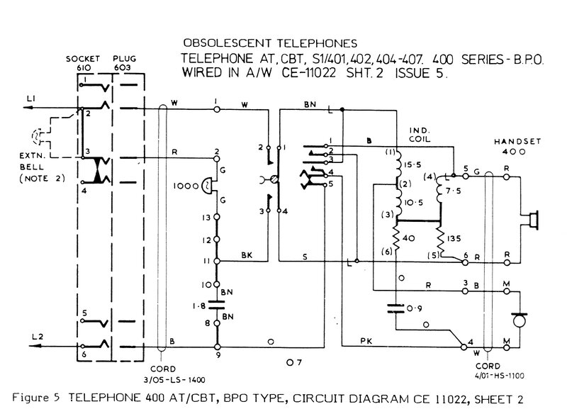
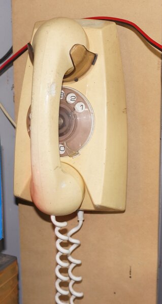
Typical circuit of an Australian telephone of the bakelite era.
Brief Operation.
In the above circuit of a 400 series phone,
we can see the bell connects across the line via a 1.8uF capacitor. Thus,
the bell responds only to the AC ring current, and ignores the 50V DC supply.
Furthermore, the capacitor prevents the resistance of the bell looping
the line when the phone is on-hook (i.e. handset in cradle).
Now a quick look at the speech and dialling
circuit. When the phone is off-hook, the gravity switch contacts make.
Tracing through from the L1 terminal, current flows through the anti side
tone induction coil, between its terminals 1 and 2. From terminal 2, current
flows via the carbon transmitter across terminals 3 and 4, through the
dialling contacts 4 and 5, and out to the L2 terminal. Thus, the phone
loops the line and speech current flows.
The dial contacts at 4 and 5 are normally
closed of course, but open and close when a number is dialled. Thus, the
loop is disconnected a certain number of times depending on the number
dialled. To prevent loud clicks being heard in the during dialling, contacts
1 and 2 of the dial short circuit the receiver.
When dialling occurs, it can be seen that
the line voltage will go from almost zero to the full 50V. Since the 1.8uF
capacitor is charged to 50V, during dialling when the line is effectively
shorted out, the capacitor discharges through the bell, causing it to tinkle
as the capacitor charges and discharges. This would happen, except for
the bell being loaded heavily by the induction coil resistance, because
of the previously mentioned contacts 1 and 2.
Contacts 3 and 4 short circuit the speech
circuit, so that during dialling the phone presents no resistance when
the dial contacts are closed. Leaving the resistance of the speech circuit
in series with the line would cause unreliable dialling on long lines.
An important feature is that the 1.8uF
and resistance of the speech circuit form an RC time constant across the
pulsing dialling contacts. This gives the correct dialling waveform, and
due to the inductive nature of the supply from the exchange, prevents damaging
voltages building up each time the dial contacts open.
Parallel operation.
Now, what if more than one phone is connected
across the line? When ring current is applied, the bells will all ring
as before, each supplied via their own capacitor. When the handset is taken
off-hook, the speech circuit will function normally. The dialling will
also function - but now the waveform will have changed shape because of
the extra bells and capacitors across the line. This is termed "impulse
distortion". Depending on circumstances, dialling might become unreliable.
A more obvious problem is bell tinkle.
As one phone is taken off hook and dialled, the bells in all the other
phones will tinkle in time with the dialling pulses. This is because the
dialling is shorting and opening the line, causing the bell capacitors
in each of the other phones to charge and discharge through their associated
bell.
This is not the correct way to connect
parallel telephones, and when bell tinkling is heard, it usually indicates
the extra phones were installed by someone unfamiliar with the correct
procedure.
Three Wire Operation.
The way around the problem is to supply
all the bells from one capacitor only. This requires a third wire.
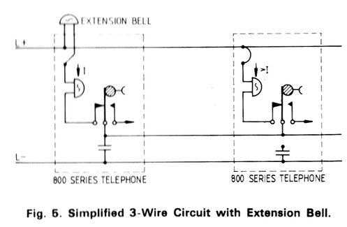
The extension bell is optional and shorted out when not required.
One of the phones is wired conventionally, but the bell capacitor in all the other phones is disconnected. All bells are linked by the third wire, and since this third wire is also loaded down during dialling, bell tinkle is prevented, regardless of which phone is being dialled from. Furthermore, since the capacitance across the line is that of one capacitor only, the correct dialling waveform is maintained.
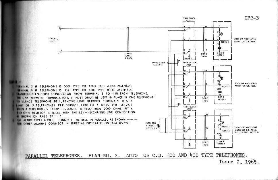
Wiring plan for parallel 300 or 400 series phones.
The above wiring plan shows in practice
how it's done. The individual phones can be configured various ways with
links on their internal terminal blocks. Here we see the bell capacitors
disconnected in the 2nd and 3rd phone, by removing the link between terminal
10 and 11.
Thus, the capacitor in the first phone
drives all three bells in parallel. As mentioned previously, with my installation,
some bells have been disconnected. This is done by removing the link between
terminals 11 and 12. In some phones, I have connected a resistor across
these terminals so that the bell works at reduced volume. In any case,
this does not affect the impulse distortion or bell tinkle suppression.
The previous description applies to Australian telephone wiring used up until the 800 series phones were phased out in the mid 1980's. Since Australian telephone practice was initially based on that in Britain, it will be noted that British telephones were used in the same way. However, when they introduced a plug and socket system for portable telephones, the bell capacitor was mounted in the first socket, with all telephones wired the same, with their bell capacitor disconnected.
Once electronic telephones came into being,
their ringers were by default not responsive to bell tinkle, and did not
cause impulse distortion. Of course, impulse distortion does not occur
with DTMF. Thus, all modern phones are two wire only. In my installation
there are two phones with two wire configuration; the Gold Phone and the
2500 series.
Since the Gold Phone was only intended
to operate as a single phone, three wire operation was not required when
it was designed. And, by this time, a clever Telecom technician had developed
an "Anti Tinkle Module" for the purpose of using newer two wire phones
with existing 800 series phones. Phones from the U.S., such as the 2500,
have always been two wire. By means of mechanical arrangements, their bells
are made unresponsive to bell tinkle.
Prior to the NBN, in my installation,
bell tinkle was heard if the Gold Phone was dialled from, and similarly,
the Gold Phone would tinkle when other phones were dialled from. However,
the bell in the Gold Phone is a soft and subdued sound, and was not annoying.
Since the 2500 is DTMF, it does not cause bell tinkle on dialling; only
when the handset is lifted. And, as the Dialgizmo keeps the line looped
when dialling, bell tinkle is no longer heard from, or caused by the Gold
Phone. The occasional "ding" from the 237AW bell is heard when a two wire
phone handset is lifted, but that is all. The bell capacitor for three
wire working is that in the 37AW; all others in the three wire phones are
disconnected.