As described in this article, converting to the NBN for my phone service entailed a number of modifications. Most significant of these was the installation of a Dialgizmo to restore decadic dialling capability to the new service. All the vintage phones could then make outgoing calls. That is, except for the Gold Phone. This problem was overcome, and the following article describes the development of a plug in interface to achieve normal operation once again.
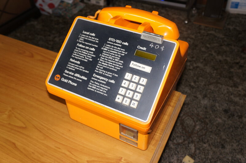
Introduction to the Gold Phone.
There is a key switch on the side of the phone with three positions; C is normal operation where the caller is required to insert coins on Chargeable calls. D does not require the insertion of coins, but the Display shows what the call charge was. This is used in situations where the caller is billed by the owner of the Gold Phone after the call; e.g. added to a restaurant bill. L is the Lessee position, and the display remains blank at all times. No coins are required to be inserted to make chargeable calls, and is used by the owner when the only phone on the premises is the Gold Phone.
Using a Gold Phone at Home.
Contrary to what has been said on various
forums, it is possible to use a Gold Phone on an ordinary exchange line,
but of course without the call charging capability. It will allow outgoing
calls and receive incoming calls normally. The key switch can be in any
of the three positions, but I keep it in the C position - the display
comes up with $0.00 when the phone is off-hook. It is not necessary to
earth the phone, but correct line polarity is important. In fact, attempts
to earth the phone resulted in hum on the line, evidently due to some leakage
causing the line to become unbalanced. While the earth connection is partly
for surge suppression, the fact that I got away without this for 23 years
would indicate it wasn't that important. Yet, the Gold Phone was exposed
to the same surges that damaged my answering machine numerous times. I
have two Gold Phones; one fitted with a 3m cord and 603 plug. This is the
one in use. The second one has a 30cm cord with a terminal block, fitted
with a surge arrestor.
Why the Gold Phone won't work with
the Dialgizmo.
After some measurements of the dialling
waveforms were taken, it became evident why the Gold Phone cannot dial
out using the Dialgizmo. The problem is essentially how the Gold Phone
loops the line, and dials. It is different to a 'normal' phone as the waveforms
show:
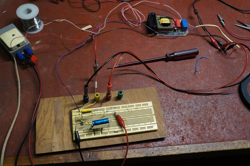
For the test, a 30V power supply was used,
with resistance to limit the current to around 30mA. While the normal telephone
supply is -48V, the difference is irrelevant for the purpose of testing.
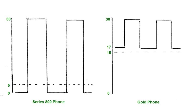
Starting with a 'normal' phone (a series
800 with mechanical dial), we can see that when the phone is off hook,
the line voltage falls from 30 to 5. When the dial is rotated to the finger
stop, the voltage falls to 0, and as the dial returns, the voltage rises
to the full 30V when the contacts open, then back down to 0 when they close
again. At the conclusion of dialling, the voltage rises back to 5V and
the speech circuit is operative again.
When the Gold Phone is tested, there is a marked difference in operation. When the phone is taken off hook, the line voltage falls to 15V. Then, when dialling commences, the voltage rises slightly higher to 17V while the dial contacts are closed, and then up to the full 30V when they open.
This is not a problem for a loop disconnect
exchange, since it senses dialling by the absence of line current. However,
the Dialgizmo operates by measuring line voltage, rather than line current.
Since the Dialgizmo was designed for mechanical dials (and the electronic
equivalent thereof), it is expecting to see something close to 0V when
the dialling commences, and each time the dial contacts close.
Hence, the Gold Phone dialler is invisible
to the Dialgizmo.
It should be noted that the Gold Phone
cannot work, even momentarily, with less than about 12V line voltage. It
will disconnect from the line, and not reconnect until the line voltage
is increased, and the phone is reset by replacing the handset.
Ideas of simply shifting the DC voltage
by connecting a 15V supply of opposite polarity in series with the phone
won't work therefore. Instead, the phone has to simulate a 0 to line voltage
during dialling, while at the same time being continuously fed with at
least 15V.
Interface allows Gold Phone to work on NBN phone lines.
Dialling Interface - proof of concept.
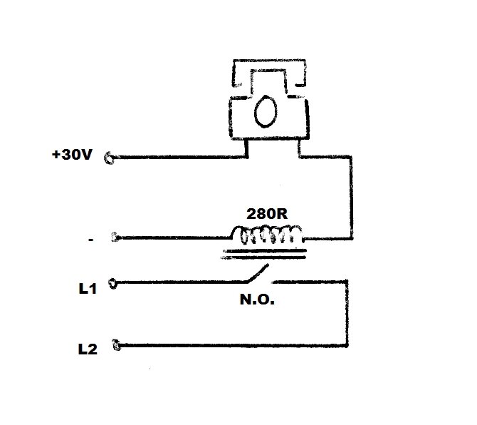
A relay coil was connected in series with
the phone and the 30V supply. 30V was chosen for convenience, since it's
what my regulated bench supply provides. It's a suitable voltage as most
phones are designed to work down to at least 24V, which is what some PMBX's
and PABX's provide. The normally open contacts were connected across the
line.
The relay responded as expected to the
Gold Phone line current, looping the line with the handset off hook, and
actuating the contacts in time with the dial. The Dialgizmo was completely
happy. So, dialling with a relay was proven. However, it's obvious there's
no way for the speech circuit to be coupled between the line and the phone,
so that although a number can be dialled, no conversation is possible.
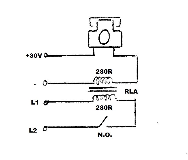
The next step was to use the second coil
on the relay as a transformer, so as to couple the speech circuits. (Some
relays are made with two coils on the one armature). Now, we had dial tone
clearly audible in the phone. Unfortunately, it was impossible to dial.
I realised what was happening. Once the contacts made, the second coil
was being magnetised with the line current, and so the relay would not
release, either by dialling or putting the handset back on hook.
It occurred to me that if the polarity
of one of the coils was reversed, the magnetism of one coil would cancel
out the other, and allow the relay to release. This looked promising, because
the on-hook and off-hook operation now worked. And numbers could be dialled
- but to a point! If any numbers greater than 6 were dialled, the relay
would stop operating. In fact it looked like it was getting weaker the
longer the pulsing occurred. Evidently, the cancelling of the magnetic
field was not quite enough. It's possible that loading one of the coils
with a resistor might have fixed the problem, but transmission would be
reduced.
In any case, the concept had been proven,
and should work if a separate transformer and relay were used.
Line Isolation Unit.
The kind of transformer suitable for this
application would be a 600R to 600R isolating type, commonly used for telephone
equipment. Looking through my cupboard of phone parts I came across a couple
of line isolation units. These were commercially made and used for isolating
things like music on hold systems, or modems, from the phone line. In the
olden days, the PMG, and later Telecom, were very strict about what could
be connected to their lines. Line isolation units prevented the risk of
240V finding its way back into the phone line, as well as preventing the
line voltage finding its way into the external equipment.
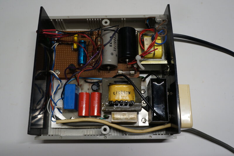
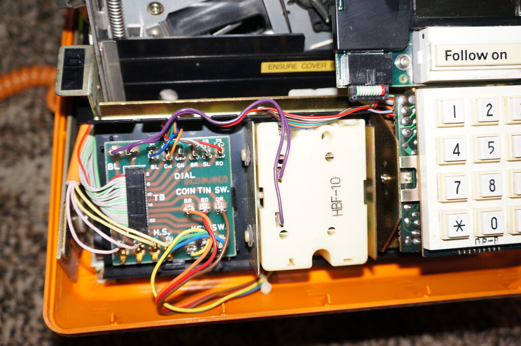
One of the LIU's looked very interesting
since it also contained three relays, as well as the right kind of transformer.
Time to trace out the circuit:
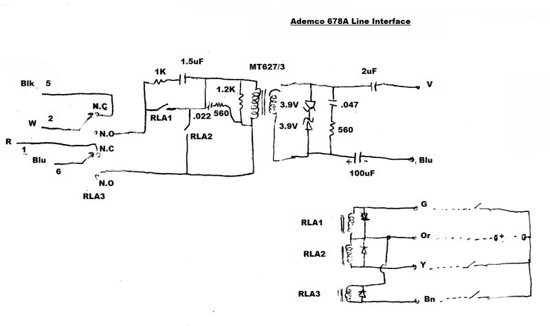
Rough sketch when I first traced the circuit.
Looking at the circuit, I could see that
most of what I needed was here and it would only take a few modifications
to convert this into the new interface. Let's first have a look at the
circuit. RLA3 switches the phone line to either the LIU or to the normal
phone. The incoming line is the usual pins 2 and 6 of the plug, and the
outgoing line to the existing telephone feeds pins 1 and 5. Unless RLA3
is actuated (the LIU is not in use), the incoming line is switched out
to the telephone which works normally. When RLA3 is actuated, the line
is switched to the LIU and the telephone is inoperative.
The line connects to the transformer primary
via RLA1. With the 1.5uF and 1K across its contacts, it was obviously used
as a dialling relay; the RC network protecting the contacts as well as
providing a suitable dialling waveform. RLA2 short circuits the transformer
to prevent pulses being transmitted across the transformer, into the following
equipment during dialling. In effect, RLA1 and RLA2 simulate an ordinary
telephone dial in this regard.
Across the transformer secondary are a
pair of back to back 3.9V zener diodes, intended to limit the audio voltage
fed into the phone line from the external equipment. There is a 2uF 440VAC
capacitor which couples the transformer to the following equipment. It
provides isolation in case the equipment under fault conditions allows
240V to be fed into the LIU. The 100uF is puzzling and appears superfluous.
The secondary is already isolated from DC by the 2uF. As it stands, the
100uF will never receive any polarising voltage anyway. It may have been
included more as a theoretical thing, to make both legs of the transformer
balanced, but in that case should be the same as the other capacitor. The
isolated signal is available from the violet and blue wires.
There are a couple of RC networks across
the transformer windings which would appear to be for frequency correction.
Each of the three relay coils is fed from
12V from the orange wire, and switched by the green, yellow, and brown
wires.
Initial Test.
By connecting the 30V supply through the
Gold Phone and through RLA1's coil, it would be possible to loop and disconnect
the line, and dial out, as previously described. But, also by connecting
the output of the LIU to the relay coil, there would be the necessary speech
circuit coupling. The unit was wired up thus:
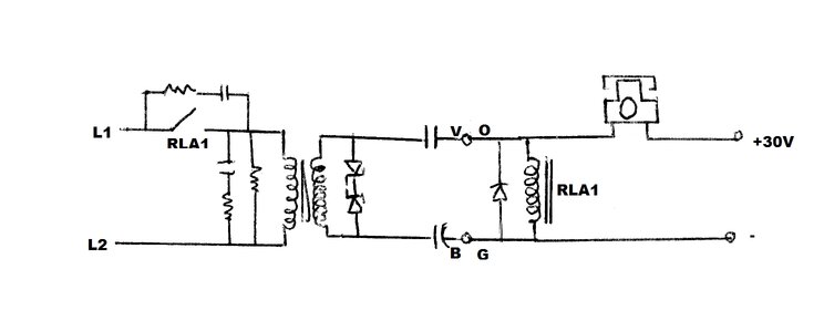
RLA1 (and RLA2) are reed relays with a
coil resistance of 650R. This is an ideal coil resistance for shunt feeding
the speech signal into the LIU. The line current through the Gold Phone
was 22mA which is quite suitable. The circuit was completely successful,
with good audio transmission and reliable dialling. The back EMF shunt
diode across the relay coil had no noticeable effect. RLA2 was not used,
since the transformer windings have a DC resistance of only 33R and would
not impair the dialling. Loud clicks would be eliminated anyway by the
dialling circuit already in the Gold Phone.
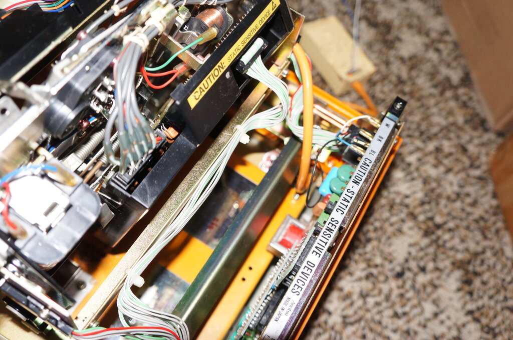
With the basic design proven, there were
some things to tidy up before making a final version.
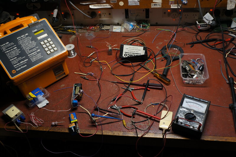
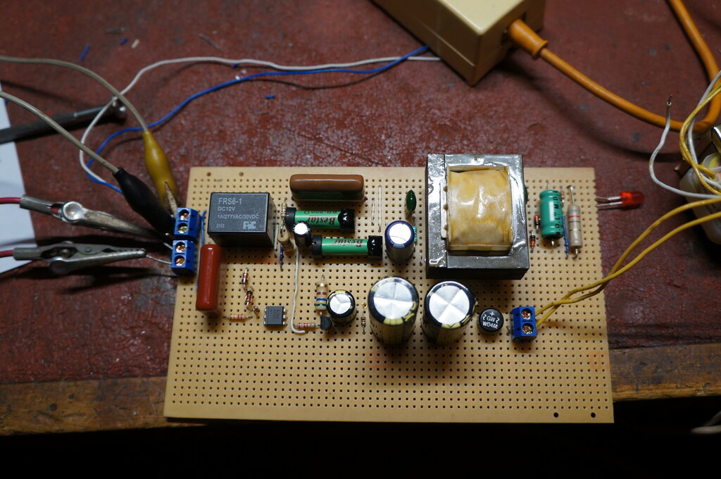
The interface under development. Many of my designs start like this.
Ring Circuit.
Since the ring voltage can't be transmitted
through the LIU, it would be necessary to switch the phone over to the
line when there was ring voltage. The hitherto unused RLA3 would be ideal
for this since it is a DPDT type. It could be actuated by a simple opto-coupler
ring detector.
I found a suitable opto-coupler on the
first PCB I pulled out of my collection of dead power supplies. It was
a Liteon LTV-816A. Because the coil of RLA3 is meant for 12V, a 560R 1W
resistor was used to allow it to work off 30V. The opto-coupler transistor
was capable of switching the relay directly, but to do so would require
more LED current than I'd like, which would load down the ring current.
Instead, another transistor was added, effectively making a Darlington
pair. This provided reliable relay switching with very little ring current.
The opto-coupler LED is driven off the phone line via a .47uF capacitor to block DC, a 22k resistor to limit the LED current, and a pair of back to back 22V zener diodes which prevent the LED responding to any low level noise. Furthermore, there is no loading of the speech circuit since the 22V is much higher than any audio voltage on the line. A 1N914 diode across the LED prevents it seeing reverse polarity when fed with AC. The circuit worked perfectly first go, and for the first time on the NBN the Gold Phone worked normally.
Ring circuit under test.
Power Supply.
The final part of the design was to provide
30 to 50V for the Gold Phone. The idea of running it off my DC solar supply
was briefly investigated, but the switchmode converter I tried caused an
audible tone in the line. Since I wanted to get the Gold Phone back in
service quickly, I just settled for an ordinary 240V powered supply. The
first likely transformer I pulled out of the drawer was a Jaycar MM-2007,
30VCT type. Rectified and filtered, it provides about 42VDC with the phone
on-hook. With one 2000uF filter there was some hum audible, which was reduced
when a resistor was connected in series with the rectifier output. It was
completely eliminated with a second filter capacitor. I may have another
look at the possibility of running the interface off 12VDC at a later date.
Given the low current required, the only challenge is eliminating noise
on the phone line. Powering the whole thing off the phone line is something
I might also give some thought to.
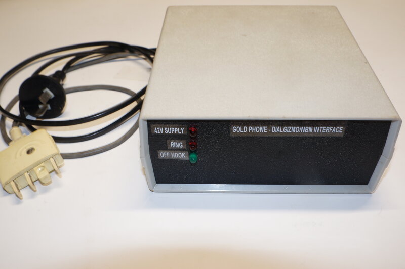
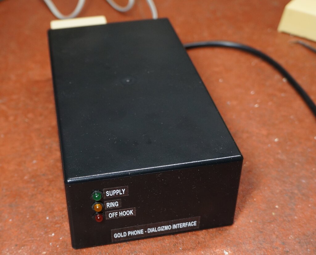
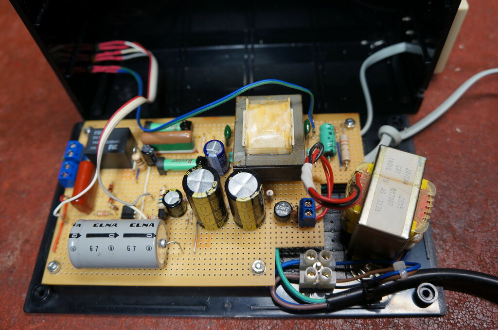
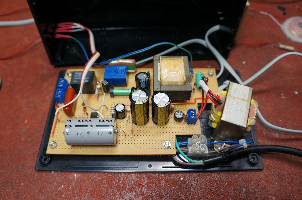
Final Assembly.
Conveniently, as most of the circuit was
already on a PCB, I only had to make up a board for the ring detector and
power supply. I also added some LED status indicators. The whole thing
was housed in a plastic instrument case.
Interface completed and working perfectly.
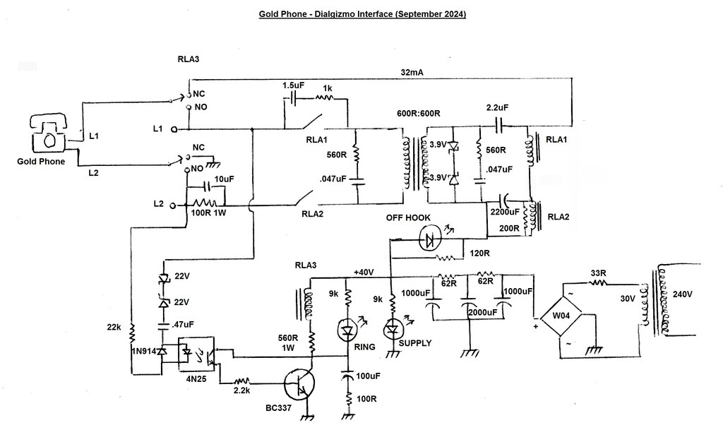
Circuit and Operation.
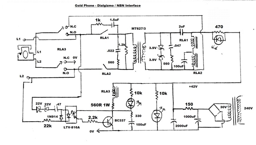
Complete circuit of the new interface. See notes further down concerning
the installation of a 100R resistor in series with the RLA2 contacts.
The open circuit line voltage to the Gold
Phone is around 42V, which is the rectified and filtered voltage from the
30V transformer. An LED shows the presence of this supply. The Gold Phone
polarity is important, and the L1 connection must be positive.
When the Gold Phone is taken off hook,
current flows through the coils of reed relays RLA1 and RLA2, through the
normally closed contacts of RLA3 and into the L1 connection of the Gold
Phone. From the Gold phone, the current leaves via the L2 terminal, through
the other set of N.C. contacts on RLA3, and to the negative of the power
supply.
In series with the reed relay coils is
another LED which simply shows current flow, indicating the phone is off
hook. It's shunted by a 470R since the line current can be higher than
the LED ratings. Current is about 25mA off hook, and not much higher if
the line is actually shorted. It therefore has a kind of constant current
characteristic.
RLA1 and RLA2 contacts now close. Current
from the L1 connection of the incoming phone line flows through RLA1 contacts,
through the transformer primary, and back to the L2 connection via RLA2's
contacts. Thus, the line is now looped and dialling can commence.
Since the Gold Phone dial interrupts the
coil current of RLA1, its contacts interrupt the line current flowing through
the transformer primary, and the line sees this as dialling pulses.
In conjunction with this, the 1k and 1.5uF
RC network across RLA1's contacts suppress any excess voltage due to inductive
components on the line, and provide a suitable pulse waveform.
RLA2 does not, however, respond to the
rapid dialling pulses. Across its coil is a 100uF capacitor which keeps
the coil energised during the loop disconnect period when dialling occurs.
RLA2 functions as the equivalent of the gravity or hook switch on a phone
- it loops and disconnects the line, but is not used for dialling. The
purpose of it is to prevent the 1k and 1.5uF loading the line when the
phone is not in use.
Since the transformer is carrying the line
current, speech signals are coupled across to the secondary. These signals
find their way into the Gold Phone via the 2uF and are shunt fed across
RLA1. Since RLA1 has a high inductance and resistance, it does not impede
the speech signals. The 2uF also prevents the low transformer winding resistance
upsetting the RLA1 and RLA2 operation, as it isolates the DC conditions.
Because the power supply has a low impedance (due to the 2000uF capacitor),
all the speech signal across RLA1's coil goes into the Gold Phone.
Conversely, speech signals from the Gold
Phone are coupled to the phone line in exactly the reverse manner.
At this point, the circuit can make outgoing
calls. Across the incoming line is a ring detector based around an opto-coupler.
The AC ring voltage causes the opto-coupler LED to pass current, via the
two 22V zener diodes, the .47uF capacitor, and the 22k resistor.
When the LED illuminates, the photo transistor
conducts, causing base current to flow in the BC337. This switches on the
coil of RLA3, which has a 12V coil drawing about 37mA. The 560R resistor
allows for 42V operation. Another LED shows the relay is being actuated,
and indicates the presence of an incoming ring signal. Because of the low
frequency ring signal, the relay would chatter during every half cycle,
when the LED in the opto-coupler is not conducting. To prevent this, a
100uF capacitor connects across the BC337 collector-emitter circuit. The
100uF holds the relay closed whilst the transistor loses conduction on
every half cycle. In series with the 100uF is a 330R resistor to limit
the capacitor discharge current when the transistor conducts. A 100uF capacitor
charged to 42V would be capable of damaging the transistor on its own.
When the ring signal is received, and RLA3 actuates, it switches the Gold Phone directly to the phone line, and the ring voltage feeds its ringer in the usual way. When the phone is answered and taken off hook, line looping occurs as described previously, the ring signal is stopped, and conversation can commence. If the Gold Phone is answered part way during the ring cycle, it will loop the line directly to cancel the ring. RLA3 will switch off, switching over the Gold Phone to the interface, which will then immediately loop the line. For this reason, the polarity of the interface power supply, and incoming phone line must be the same.
In summary, the Gold Phone is effectively being used as a local battery phone with a current and voltage that it's compatible with. The outside line conditions are now unimportant. Similarly, true dialling is made possible because the dialling relay provides a full loop disconnect.
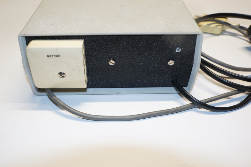
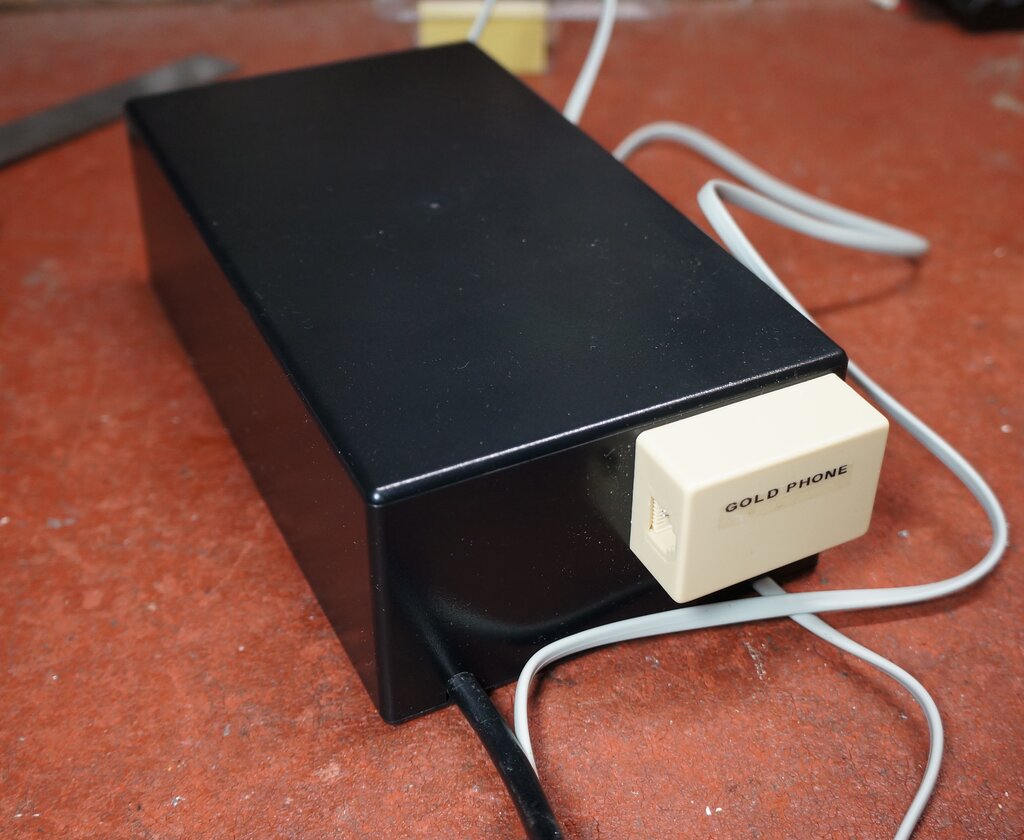
Gold Phone plugs into socket at rear of interface.
Surge protection has been installed at the phone output of the Dialgizmo, to protect it and the modem. A 90V gas arrestor is used along with 500mA fuse in each side of the line. The arrestor is earthed through the mains.
New interface constructed with readily available parts.
Circuit of new interface using new parts.
Initial testing of the 2nd version revealed a few modifications
were needed. Both relays in the speech circuit were at this stage of development
5V 500R reed relays.
Some initial difficulty was had with the interface dialling wrong numbers. It was assumed that RLA1 would be the problem, since this creates the dial pulses seen by the Dialgizmo. Looking at the dialling waveform showed a very slow release time. Reed relays are supposed to be able to switch very fast, so it was at odds with what was expected. For testing, a conventional 12V relay was substituted, and this dialled perfectly. So why wouldn't the reed relay work? The relay was tested with a square wave function generator driving the coil through a diode. It easily switched up to at least about 200Hz. 10Hz from a dial should be no trouble!
First thoughts were that because the two relays were mounted close to each other (as in the above photo), the line looping relay (RLA2), was leaking enough magnetic field to the dialling relay (RLA1), to slow down the release time. Strangely enough, inserting a piece of steel between the relays to shield them from each other seemed to fix the problem. I then relocated RLA1 further away, but the problem was still there.
It was then found that the line current
through the Gold Phone (about 25mA) was excessive for the relay coil, which
should have only 10mA passing through it. Reducing this was achieved by
connecting a 560R resistor in series with the reed relay coils. Since the
line current was now inadequate for the Gold Phone, a 820R shunt resistor
was connected across the relay coil circuit, giving about 35mA line current.
It was felt that the 25mA used in the first interface was at the lower
limit of being acceptable, and with the particular Gold Phone being used
for testing (not the same one as the first), 25mA gave less than satisfactory
speech performance.
With the line current now increased to
35mA, the resistor shunting the red "Off Hook" LED was reduced to 120R
from the original 470R.
The hum from the power supply was felt to be higher than it should be, and was probably caused by the increase in line current. To improve this, a three stage filter for the 40V supply was implemented. Further reduction in hum was obtained by including the 33R resistor in series with the AC input of the rectifier. This reduces the input capacitor peak charging current. The supply drops to around 31V when the phone is off hook. An active filter/regulator could have been used, but it was felt the extra complexity was not justified.
The capacitor across the RLA2 coil was
increased from 100uF to 220uF, since with the relay specified the hold
in time was insufficient. This resulted in RLA2 responding to the dial
pulses, whereas is should stay closed throughout the dialling period..
The ring relay (RLA3) holding network
required the 330R be reduced to 100R, to prevent this relay responding
to individual pulses of the ring voltage.
First lot of modifications were still not reliable.
Unfortunately, operation was still unreliable.
It seemed the current through RLA1's coil was just too critical for dialling.
A slight change in supply voltage was enough to cause erratic performance.
At this point I decided to change this relay to a conventional type. This
also resulted in an improvement with speech quality, because it had a higher
coil inductance than the reed type used. This allows more audio voltage
to be developed across its coil.
The relay chosen was a 12V SPDT type with
a 300R coil. It is of enclosed construction, so it is felt that the contact
reliability should be good enough. Certainly, the dialling performance
is far superior. To restore the correct line current for the Gold Phone,
the 560R between relay coils was removed and shorted out, and so that RLA2
is fed with correct voltage and current, a 200R resistor was connected
in parallel with its coil. Line current is 32mA. Voltage across the Gold
Phone off hook is 16V.
Yet again, wrong numbers were sometimes
dialled. This was quickly narrowed down to the fact that RLA2 was no longer
holding in long enough, and was also contributing to dial pulsing. Connecting
the CRO across its contacts showed the contacts opening during dialling.
The reason was that with 120R now in parallel with the coil, the time constant
was much reduced. To restore this, the previously used 220uF was increased
to 2200uF.
Final version working as it should. Note the dialling reed relay
has been replaced by a conventional type.
RJ socket connects to Gold Phone. Grey wire to Dialgizmo.
 *I
appreciate the interest this article has created but, unfortunately, I
am unable to manufacture and sell these interfaces. I can only provide
constructional information.
*I
appreciate the interest this article has created but, unfortunately, I
am unable to manufacture and sell these interfaces. I can only provide
constructional information.