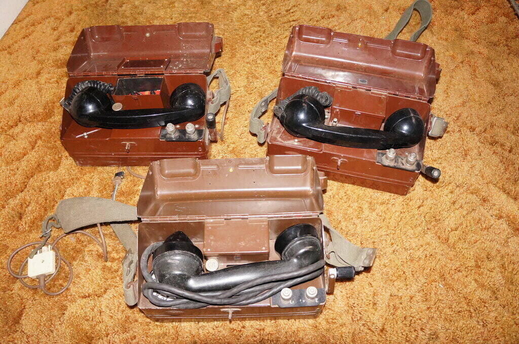
Some of the collection.
Some of the collection.
These telephones were used by the PMG as
a portable linesman's phone. Although they are not particularly uncommon,
I have not found any relevant Australian literature. Initially, they were
made by Ericsson in the UK, with the last examples branded Plessey.
Fortunately, I was able to track
down some useful information on the British
Telephones site. In that site is a section concerning Ericsson,
and here I was able to find information on the models used in Australia.
The model of interest is the N1845, and in this article we will look at the variants used by the PMG in Australia.
All Exchange Types.
One version seen is for magneto or CB
(Central Battery) exchanges. More commonly, a dial is also provided, which
allows automatic working.
This version could thus work on any type
of exchange; magneto, central battery, or automatic. The phone always operates
as a local battery type, regardless of exchange. Transmitter current is
provided by a 3V battery. They can, of course, be used as field telephones
in the usual way, with magneto calling between units.
The telephone is based on the earlier
J and L types, used by the military. It is constructed in a steel box with
hinged lid, and can be operated with the lid closed, since cable entry
points are provided. This would provide some weather protection when working
outdoors. Two nickel plated brass binding posts connect to the line. The
magneto handle can be folded down when the instrument is being carried.
A woven shoulder strap allows fully portable
operation, such as up a pole. The strap also allows for holding an earth
rod. No earth rods have yet been sighted.
From what I have collected, it appears there are three variants, spanning from the 1950's to the early 1970's. My first encounter with these phones was in 1980, when a neighbouring friend and I linked our houses together, using an aerial line and earth return.
Background.
The general design originated in the UK,
it seems as far back as 1932, with a magneto only version, designated N1843.
Circuit
N66906 here.
Next was the military Type
L which works on magneto and CB.
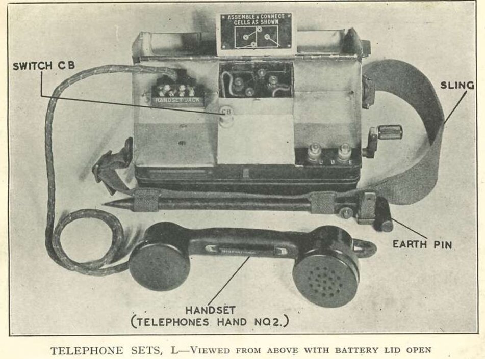
Taken from https://fieldphones.org/009-british-fieldphones/
this shows the earth rod secured to the shoulder strap.
Type
J which appeared in 1946, has a permanently attached handset cord,
along with terminals for an extra receiver. It is also for magneto and
CB. Circuit
N69106 here.
Mistakenly, the PMG issued telephones
are often being sold as WW2 artefacts (with a suitably inflated price),
no doubt due to their appearance, being similar to the L and J type. However,
the military version was not painted brown and did not include a dial.
1) Early Type (P.M.G. 51.611P).
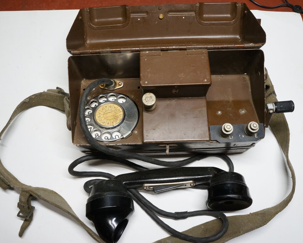
Although not actually stamped on the instrument
anywhere, the circuit N69166 identifies it as an Ericsson N1845. This model
appeared in 1946 (in the UK at least).
As the photo shows, it uses a variant
of the 184 handset, as used with series 300 telephones. This contains a
No. 13 transmitter and 2P receiver. The difference is the addition of a
"Pressel" switch (press to talk) mounted in the handset. This is necessary
since there is no gravity or hook switch, to disconnect the transmitter
battery when the phone is not in use. The handset connects to the instrument
via a heavy duty rubber cord.
For one of this type of telephone in my collection, the transmitter was constantly operating regardless of the Pressel switch. The result was of course continuous battery drain. The fault turned out to be leakage in the bakelite handset itself. The wires moulded in the bakelite are not insulated. To fix it, I drilled into the side of the bakelite, removing it all which surrounded the switch wires, and then used car body filler to fill it all back in. I never found exactly what the leakage was from, but the repair was completely successful.
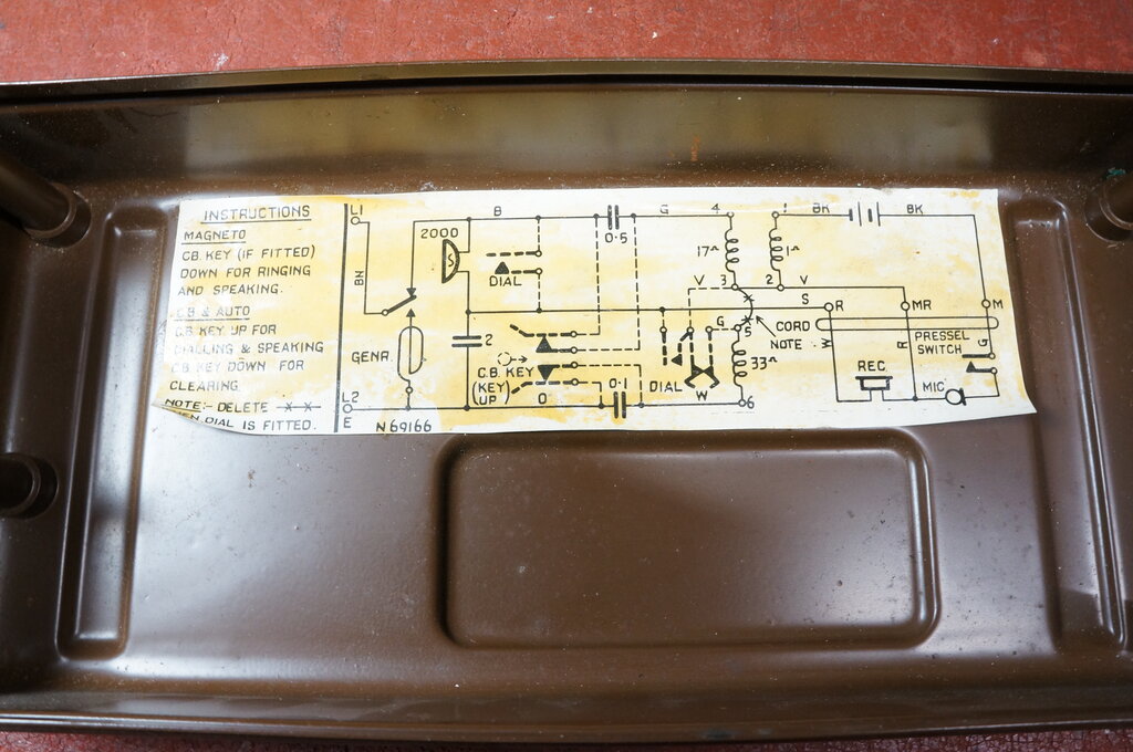
Circuit N69166 of early type.
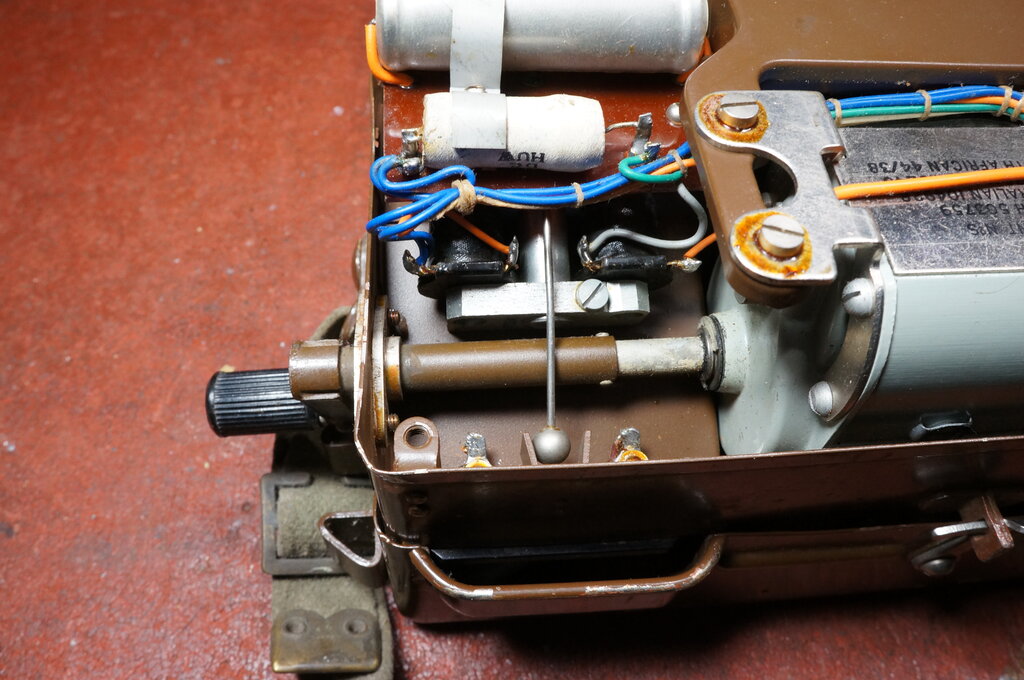
Details of the bell.
The bell motor is similar to a domestic series 300 instrument, but without gongs. Instead, the clapper strikes a bracket on the front of the case. The effect is a loud clicking sound.
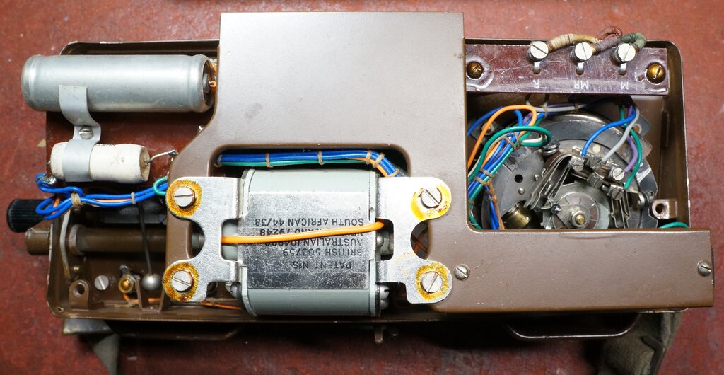
Capacitors, magneto, and dial.
Electrically, it is really a magneto telephone which has been adapted for CB and automatic working. The ASTIC (anti side tone induction coil) is similar to the type 21A, but does not contain the 900 ohm resistance. The magneto is a type C, which is same as used in the Ericsson series 300 instruments. Dials are type 10 or 12. Unlike the domestic series 300 and 400 magneto telephones, the magneto is connected so that the telephone does not have to be on hook to call out. This is simply achieved by altering the connections to the switch on the back of the magneto.
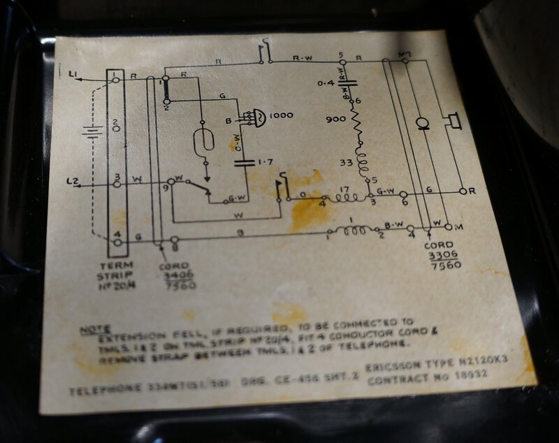
Circuit of domestic series 300 magneto phone, for comparison. Note
the difference in magneto switch connections.
There is no gravity switch for the handset, so for CB and automatic working a key switch is provided. This connects between the line and speech circuit. The key is pulled out to loop the line, and pushed in to disconnect it. Note the 0.1uF and 0.5uF capacitors, which are in circuit when the key is pushed in (i.e. "on hook"). This allows the line to be monitored without creating a DC loop, and signalling the exchange. The dial is the same type as fitted to series 300 automatic instruments.
For the magneto only version, there is no key switch or dial.
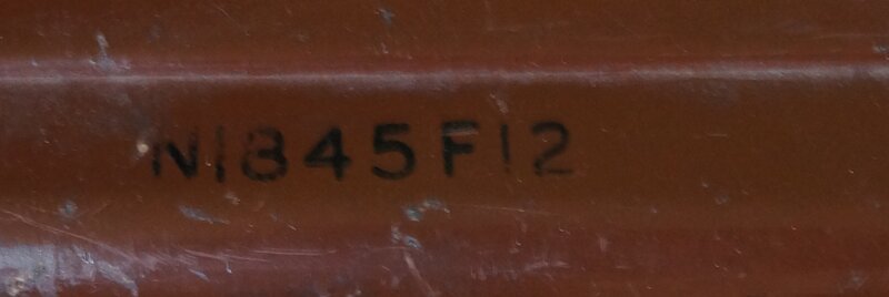
2) Second Type N1845F12
Changes are:
For magneto working, the current path through the bell identifies a continuous line to the exchange or other phone being called, since the local bell rings on outgoing calls. Presumably, only one bell coil is in circuit so as to minimise loss of magneto current. When calling out, the bell is quieter than for incoming calls.
Battery Feed.
The other significant change is that the
telephone now provides line current when calling a remote CB or automatic
telephone. Previously, it would be impossible for a two way conversation
to take place. A scenario might be the linesman wanting to communicate
with a CB or automatic subscriber on a disconnected exchange line. The
subscriber's phone would ring, and they could hear the lineman, but the
lineman would not be able to hear them.
The battery feed operates whenever the
CB key switch is lifted, regardless of the Pressel switch. It can be seen
that depending on line polarity, the battery will either discharge or recharge
accordingly. The purpose of the 330 ohm resistor is not entirely clear,
but my guess is it compensates for the higher efficiency of the 4T receiver,
since this is more sensitive than the older 2P type. That is to say, it
restores the correct level of sidetone. This circuit appears to be based
on the Ericsson type N86997, which differs in that has no 330 ohm resistor,
and the magneto current does not pass through the bell.
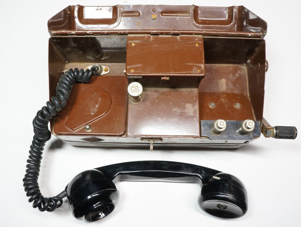
Handset now a No. 6, and dial cover added.
The circuit is CE11192, issue 4, implemented 19/4/1966.
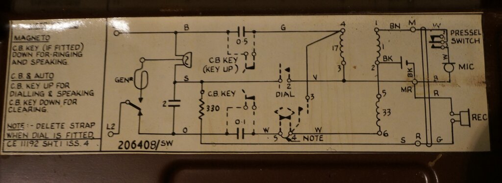
Circuit modifications include battery feed and a 330 ohm resistor
in series with the receiver.
It can be seen that when the line is connected and the CB key is up, battery current flows through the 17 ohm and 33 ohm windings of the ASTIC, and into the line. Effectively, the windings function as retard coils (audio chokes).
An interesting feature, though no doubt unintentional, is that with an auto or CB line, the transmitter will function without the battery. The Pressel switch must be held down to loop the line. In this configuration, line current flows through the 17 ohm winding, through the transmitter, the Pressel switch, the 1 ohm winding, and then the 33 ohm winding back to the line.
Because of this characteristic, the battery is subjected to about 50mA charge current, or discharge current, depending on line (or battery) polarity. This occurs when the CB key is up and the telephone is connected to an exchange line. Battery current when the line is short circuited is about 75mA. On its own with the CB key down, the transmitter current measured on two examples was about 4 to 18mA. This varies with the condition and position of the transmitter.
Line Polarity:
During testing with the Simple
Telephone Intercom, it was noted that operation was sometimes quite
poor. At other times, it was normal and quite good. The fact that the battery
was in circuit caused suspicion to fall on line polarity. After all, the
battery is the only polarity dependent component in the telephone. Indeed,
this turned out to be the case. Measuring the line voltage with an oscilloscope
revealed a marked difference, from when line polarity was changed from
one to the other.
With the battery connected as shown, L2
must be connected to the positive side of the line. An easy way to remember
this is L2 is also designated E, and that telephone systems operate with
a positive earth.
Connected thus, the battery current direction
is such that it charges. The cause of the problem was that with 'incorrect'
polarity, the line voltage was falling to about 1.6V. This is because the
battery voltage (3V) was being subtracted from normal off hook line voltage
(about 4.5V).
This is an important point to observe,
if using one of these telephones with a simple type of line feed, where
both telephones share the line current. If operation seems poor, reverse
the line polarity. Even with a 'proper' feed, it's worth using correct
polarity just to lengthen battery life.
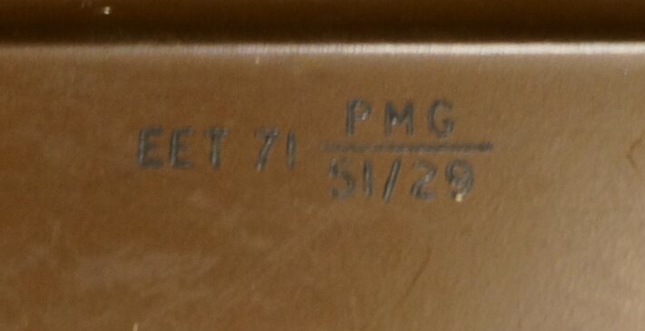
Under the case is printed EET 71 PMG S1/29. This was manufactured
in 1971. EET would be the manufacturer code; presumably one of the "E"s
stands for Ericsson.
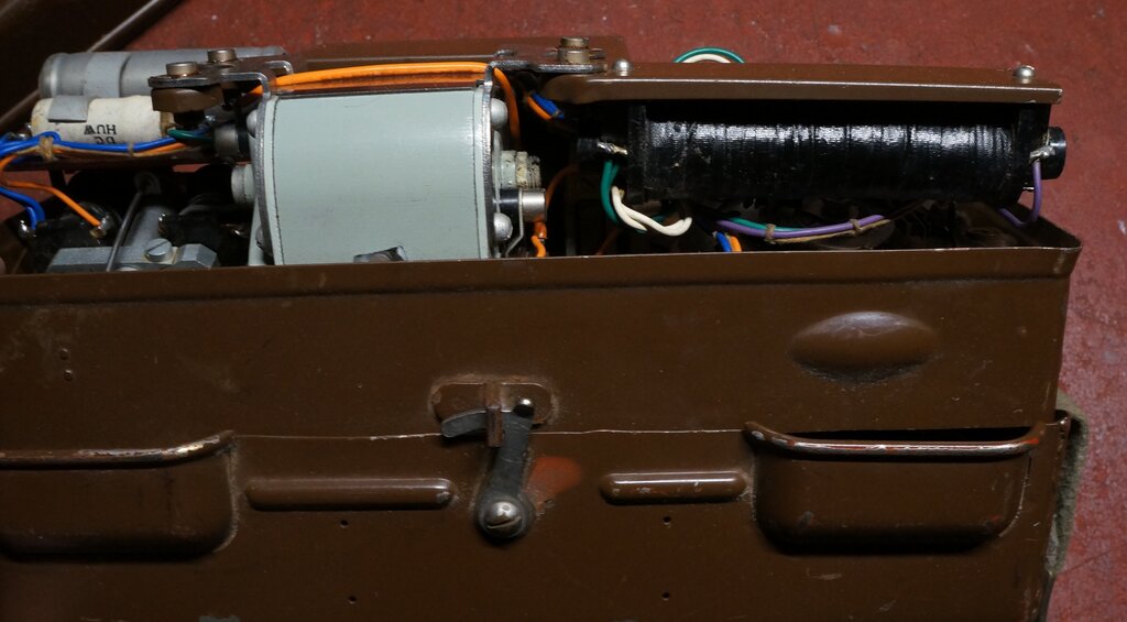
Magneto and Anti Side Tone Induction Coil shown here.
3) Third Type (N1845F23T).
This looks the same as the second type,
with the 700 series handset and dial cover, but with two additional points
of difference. There is a Plessey logo on the inside of the lid, and the
battery wiring diagram is now black on white, instead of the previous black
on red.
There is no stamping under the case as
per the N1845F12. Battery feed is also incorporated. One unit examined
contained a No. 16 transmitter.
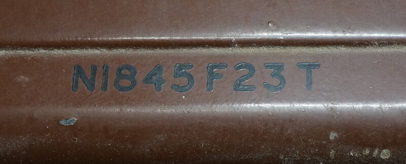
Number on lid designates this as the third type. N1845 variant.
F signifies Auto, CB, Magneto.
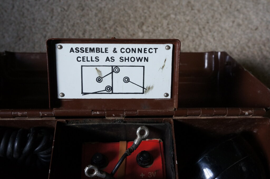
Wiring diagram for battery is now black on white.
Internally, the ASTIC has been changed to one of different physical construction, and with lower resistance windings.
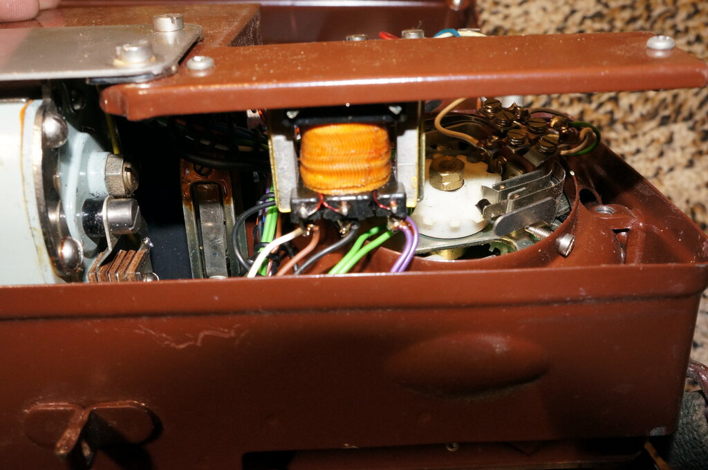
ASTIC is now much smaller.
The circuit is CE11192, issue 5.
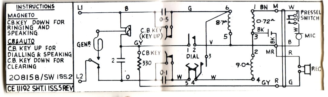
Note the lower resistance for the ASTIC windings.
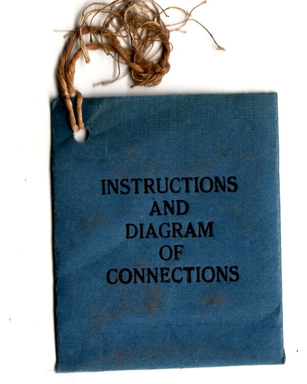
Paper bag to store circuit diagram. This was found in the battery
compartment.
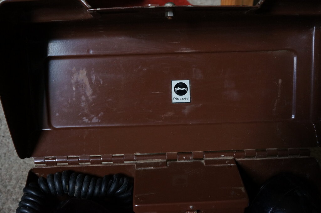
Plessey logo in lid.
From an internet advertisement, this lists the changes over production.
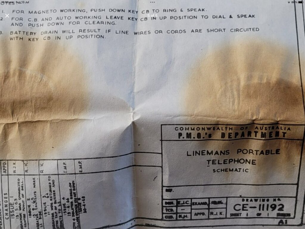
Note the circuit diagram is designated CE-11192. This appears to be locally created by the PMG. The equivalent Ericsson type is N86997, but it differs in that it uses the original ASTIC and has no 330 ohm resistor.
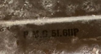
Stamping on lid indicates P.M.G. 51.611P
The stamping on the lid is the same as the dial equipped instrument. This leads one to query the PMG allocated number. Were the telephones being assembled here, or was the Ericsson number simply ignored in preference to a locally allocated type?
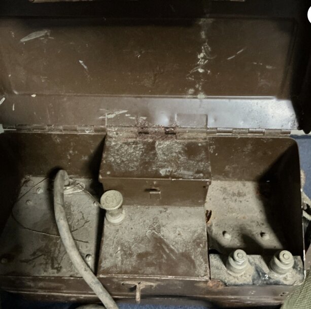
A blanking plate is fitted over the dial location.
5) Headset Socket (N1845F8).
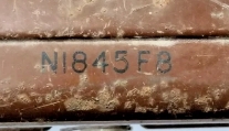
N1845F8 stamped on lid.
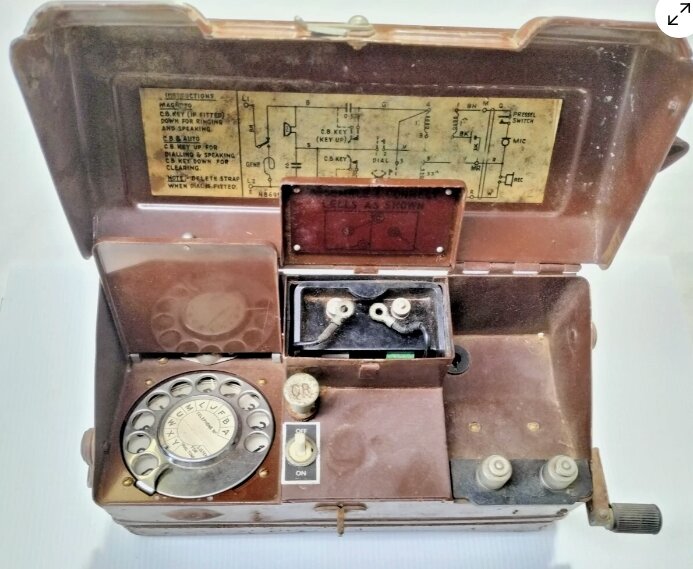
Note the toggle switch, and also the battery adaptor.
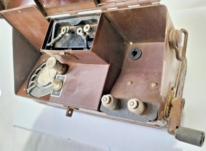
Headset socket is fitted in corner of handset compartment (Photos
from eBay ad).
This type would appear to be a local modification
to take a headset. There is a 1/4" phone jack, and a toggle switch in front
of the CB switch. Presumably the switch is for the headset transmitter.
This is not a one off modification, since more than one of these units
has been seen.
The original handset termination is unclear,
since the waterproof gland behind the dial is still present, but without
any cord. This type has not been examined in person, so this is all assumption.
6) Magneto Only (N1845J).
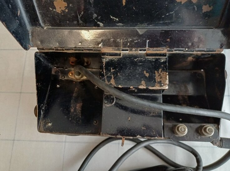
This image is taken from a UK eBay ad. The point of interest is the CB key position is blanked off. As far as is known, this type was not used in Australia.
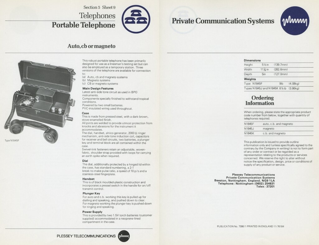
From a Plessey catalog, possibly 1976.
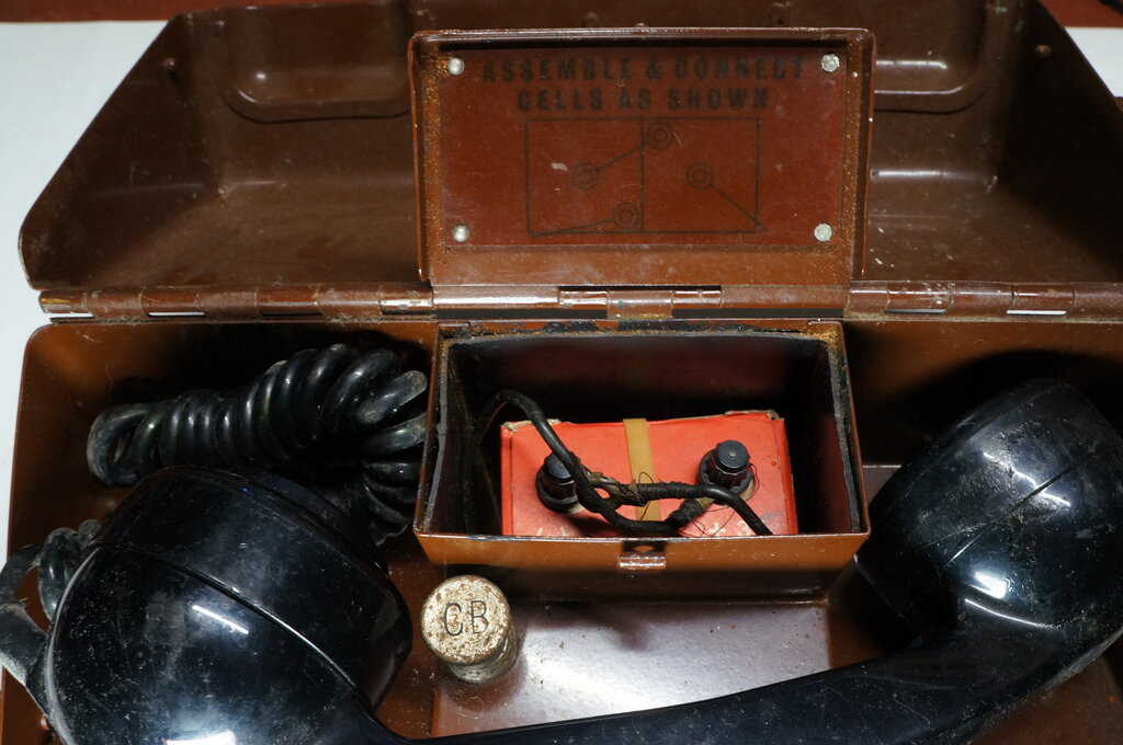
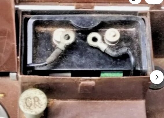
Battery wiring diagram. Eveready Q549 installed.
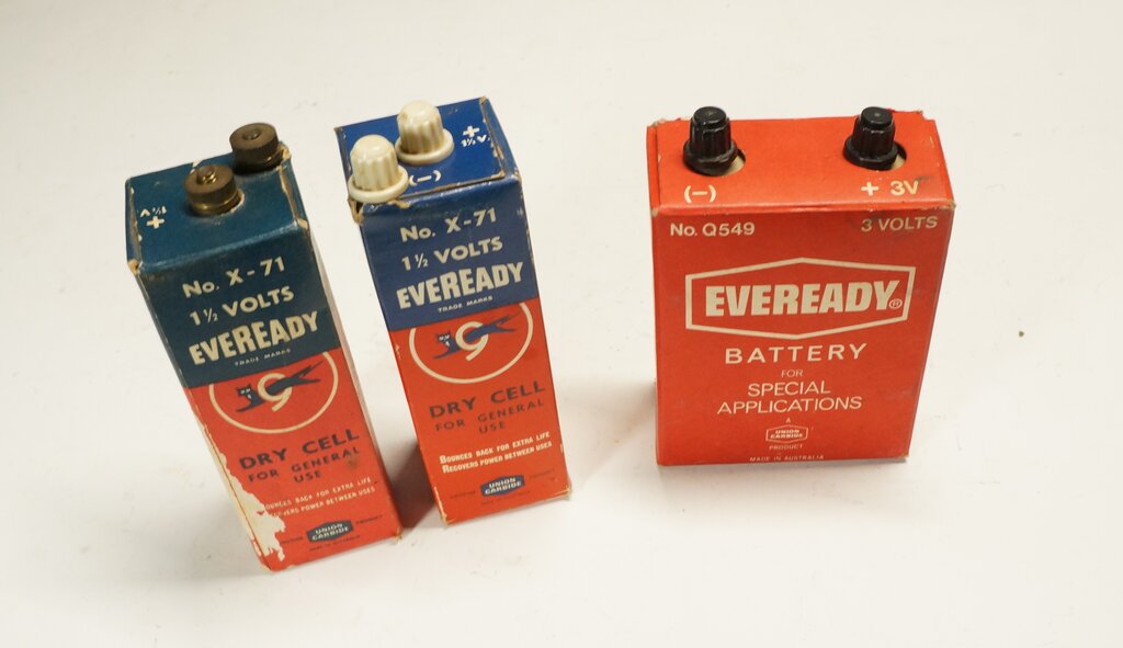
Two types of batteries which have been used.
Initially, the battery consisted of two
X-71 cells in series. Internally, these consist of an "F" size carbon zinc
cell. F cells are the same type used to make up 6V lantern batteries (such
as the 509, 731, etc.). The X-71 is apparently just designated as a type
X cell, in the UK.
Next was the Eveready Q549. This consists
of two carbon zinc D cells in series.
As such, both types of battery can easily
be restored in the modern day to retain an authentic appearance.
With care, the bottom of the X-71 can be opened without too much tearing of the cardboard. The paste which was used to glue the bottom flaps has become brittle over the years, and is not difficult to break apart. The old cell can be slid out, and a new cell soldered in. Instead of using an F cell, a D cell can be used with a cardboard spacer at the bottom. The cardboard flaps can be secured with silastic, so that the cell can be opened again without damaging it.
The Q549 battery is even easier, as there is no glue. The box is opened like any other from the top. Again, two new cells can be soldered in and the box closed up.
As to what cells to use, unfortunately,
in the modern day, alkaline cells are not recommended, since virtually
all examples now available will leak at some point. And it is well to remember
that with these batteries being used intermittently, and with a very low
current drain, they will otherwise last their shelf life, which is many
years. Because the cells last so long, they are forgotten about - until
transmission performance drops off, and by that time the electrolyte has
leaked out and damaged the cardboard.
My first recommendation is non-rechargeable
lithium cells. For 1.5V, these appear to only be available in AA and AAA
sizes. These will easily provide the transmitter current, but some kind
of packing will be needed to fit them inside the original cardboard carton.
NiCd or NiMh cells are also chemically stable and are an alternative, provided
they are recharged every so often. Their self discharge rate is higher
than lithium, and will require recharging from time to time.
For the Q549 shown, I installed a single
D size lithium 3.6V cell as used for alarms. It has a capacity of 45Ah,
so will probably see me out. A wooden spacer occupied the space vacated
by one of the previous C-Zn D cells.
For the X-71's, I installed D size NiCd
cells, of 4Ah capacity.
It is probably inadvisable to use lithium
cells in the versions of these phones which have battery feed, and
are used on auto or CB exchange lines. Lithium cells might not take kindly
to being charged. Carbon zinc, alkaline or NiCd/NiMh would be preferred.
At the time of writing, an eBay seller (batteryadaptersuk) in the UK is 3D printing X cell replicas, which take a C cell. An AA lithium cell could easily be used, since AA to C adaptors are readily available.
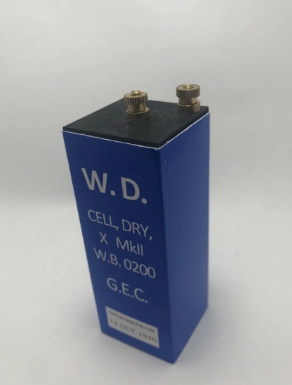
Replica X cell available on eBay.
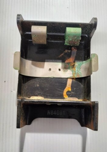
Ericsson Battery Adaptor.
Supplied with the last generation of phones,
this takes two D cells. It is fitted with two nickel plated brass binding
posts. Part number is N84081.