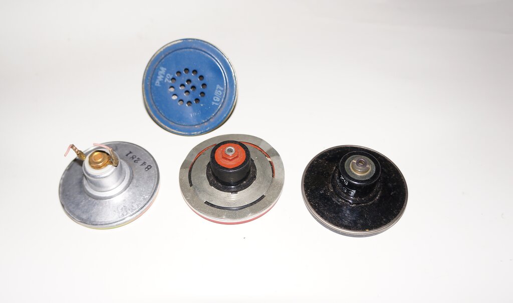
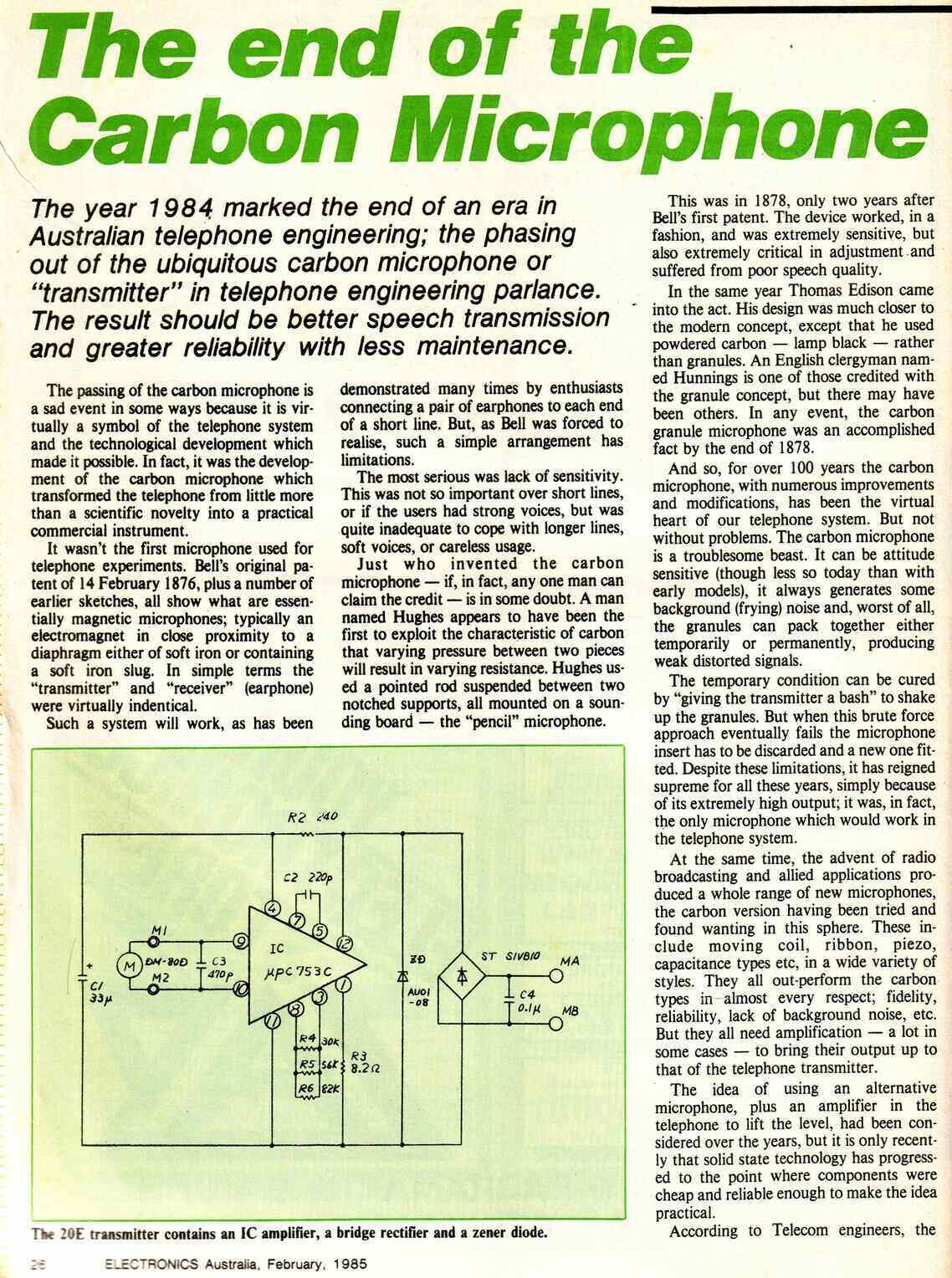
An array of No. 13 transmitter inserts. At left is the type used in the 800 series phones.
To prevent confusion for those not familiar with telephone technology, two terms need to be defined at the outset. In telephone parlance, a "transmitter" is what is generally known as a microphone. It "transmits" the voice from the telephone instrument. Conversely, the "receiver" reproduces the voice, and is simply an earphone or very small loudspeaker. These terms are likely to be confused with the same as used in radio, but remember that telephone technology predates that of radio.
Carbon Transmitters.
No other microphone provides an output
as high as that of the carbon type, which is why it was used for so long;
over a hundred years, in fact. A carbon transmitter on its own, supplied
with only a few volts, can easily drive a receiver many miles distant.
Note that electronic amplification did not exist when telephone technology
was established.
The basic principle is one of carbon granules
being loosely packed behind a diaphragm. As the diaphragm vibrates with
the incoming sound, the carbon granules are more or less tightly packed
depending on how much the diaphragm is deflected.
The carbon granules rest between two contacts,
through which current flows to the external circuit. As the carbon granules
are pushed closer together, the resistance drops, and the looser they are,
the higher the resistance. The result is a current varying with the sound.
An array of No. 13 transmitter inserts. At left is the type used
in the 800 series phones.
Carbon microphones can be designed to handle
high currents. One type of portable public address system consisted simply
of a carbon microphone, battery and horn speaker. In the early days of
radio transmission, a high powered carbon microphone was used to directly
modulate the current fed into the transmitting aerial. One can see that
considerable amplification is possible without any active electronic components,
such as valves or transistors.
Carbon transmitters are not without problems.
Particularly with well used examples, where the granules have become worn,
the output can become weak and distorted. The position in which they are
used can be critical if all the granules clump together. Transmission efficiency
in telephones is reduced with reduced line current, as occurs with long
lines. Noise is generated because of DC being passed through the carbon
granules. Furthermore, although not of great importance as far as voice
communication is concerned, the fidelity is poor with high distortion and
limited frequency response.
Despite these disadvantages, the carbon
transmitter is rugged and inexpensive.
The most common type of carbon transmitter
used in Australian telephones was the No. 13., which was used in the 300,
400, and 800 series phones.
![]()
Background to Electronic Transmitters.
As solid state technology developed, it
was only natural that thoughts should turn to substituting the carbon transmitter
with a dynamic or electret condenser type which would eliminate all its
problems. On their own, dynamic or electret condenser microphones do not
provide anything like the output of a carbon type. Therefore an amplification
stage is essential. The transmitter also has to present a certain load
to the line, operate over a range of line currents, and be immune to damage
from excess voltage. Since the replacement transmitter has to substitute
for a carbon type, it also has to be two wire working; that is, the amplifier
is powered from the same two wires across which the audio is developed.
Of course, the transmitter must also be polarity independent.
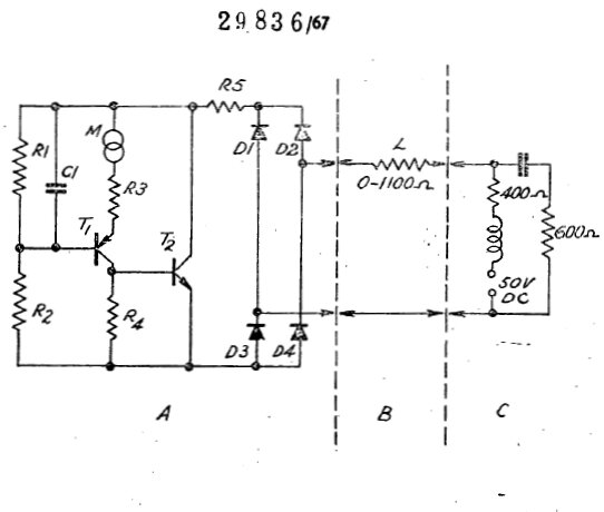
The following circuit is an example of how the concept is applied. It is not of my design (if it's yours let me know!).
![]()
The incoming supply is first fed through
a bridge rectifier, with two of the diodes being 10V zeners. As well as
making the transmitter polarity independent, the supply voltage is limited
to about 10V. This is important for protection of the amplifier and microphone.
There is a single transistor amplifier,
self biassed by the 100k resistor, so that a suitable amount of current
is drawn, which would typically be around 30-50mA. The telephone must draw
a certain minimum current (25mA) for the exchange to sense that the line
has been looped and is in operation. In typical telephone circuits, the
entire line current flows through the transmitter.
The transistor base current is also modulated
by the microphone output, and thus the current draw will fluctuate around
the standing 30-50mA, with the user's voice.
Since the microphone is an electret condenser
type, it needs its own DC supply. To obtain this, the 10uF capacitor filters
out the audio component developed across the transistor. So as the capacitor
does not short out the audio signal, it is isolated by a 4.7k resistor.
The microphone is then fed with DC in the normal way via the 4.7k load
resistor.
Note that I have not tried this circuit,
but it appears to be an excellent starting point for anyone wishing to
experiment.
In Australia.
Ideas of producing an electronic transmitter
replacement go back to at least 1967, as described in a patent from AWA.
Along with STC, AWA had been producing telephones since the start of Australian
production of the series 300.
This patent provides some very useful
information as to the design criteria, and also describes the characteristics
of the exchange supply and subscriber line:
20E transmitter fitted to a later 807 handset. This particular transmitter
was made by AWA.
20E retrofitted to an earlier 800 series handset. This version was
made by NEC and includes the handset cord clamp.
Not a lot seems to have come from AWA's patent, in terms of any transmitters being produced. As the following article explains, in 1977, NEC commenced the design of what was to become the 20E transmitter.
The 20E transmitter was very successful, being used as a replacement in existing 800 series telephones, and as standard fitment to the the "New Standard Telephone" which appeared in 1984 (807 - table, 897 - wall). The NST was the last attempt at modernising the series 800, and while the external appearance is similar, except of course for the push button dial, internally the two designs are completely different.
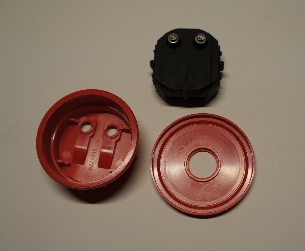
The 21A is a drop in replacement for the No. 16 carbon transmitter.
In Britain, a similar path was taken to replace the No. 16 carbon transmitter used in their series 700 telephones.
700 handset and the No. 16 transmitter.
In this case, the IC was developed by Ferranti,
who were later taken over by Plessey.
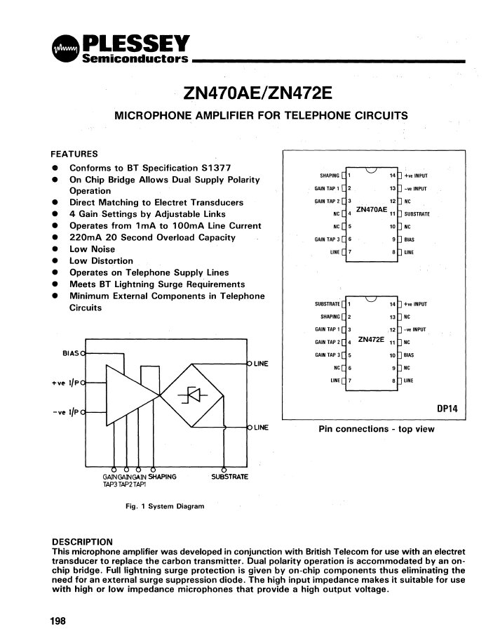
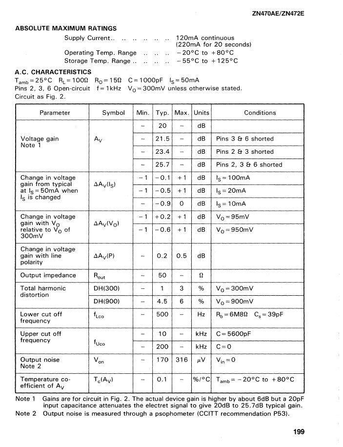
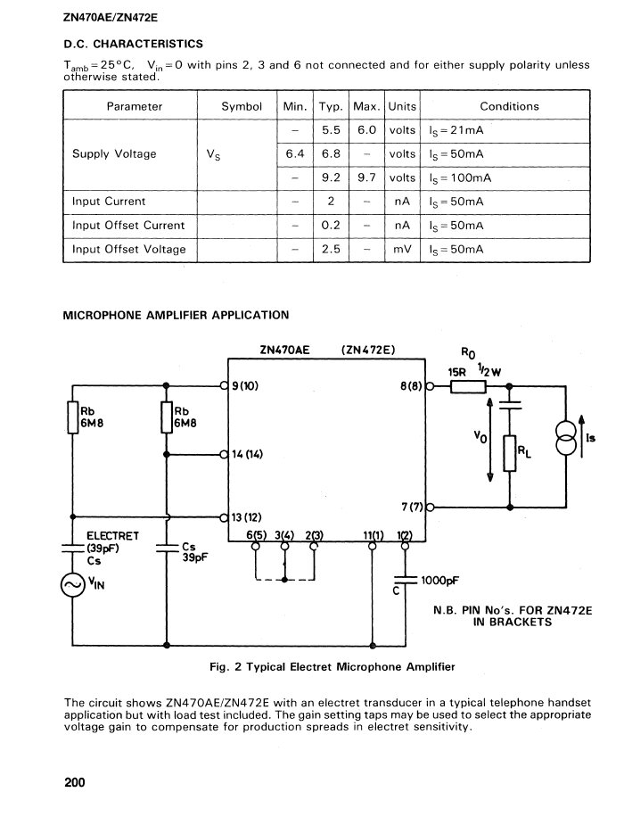
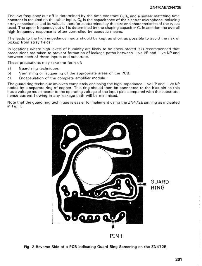
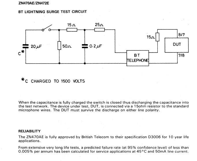
Data and application notes for the ZN470AE.
It all clips together.
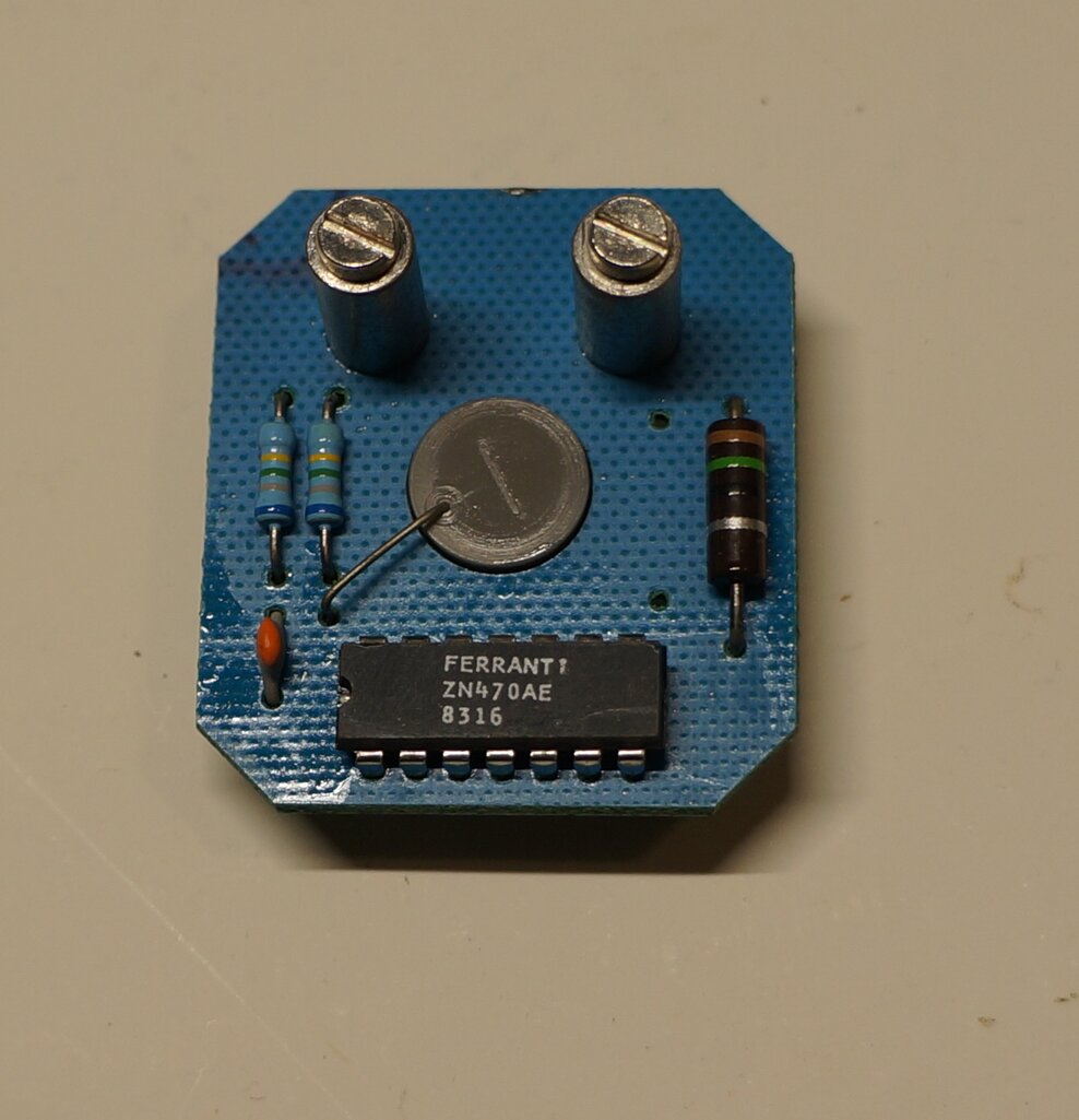
Component side.
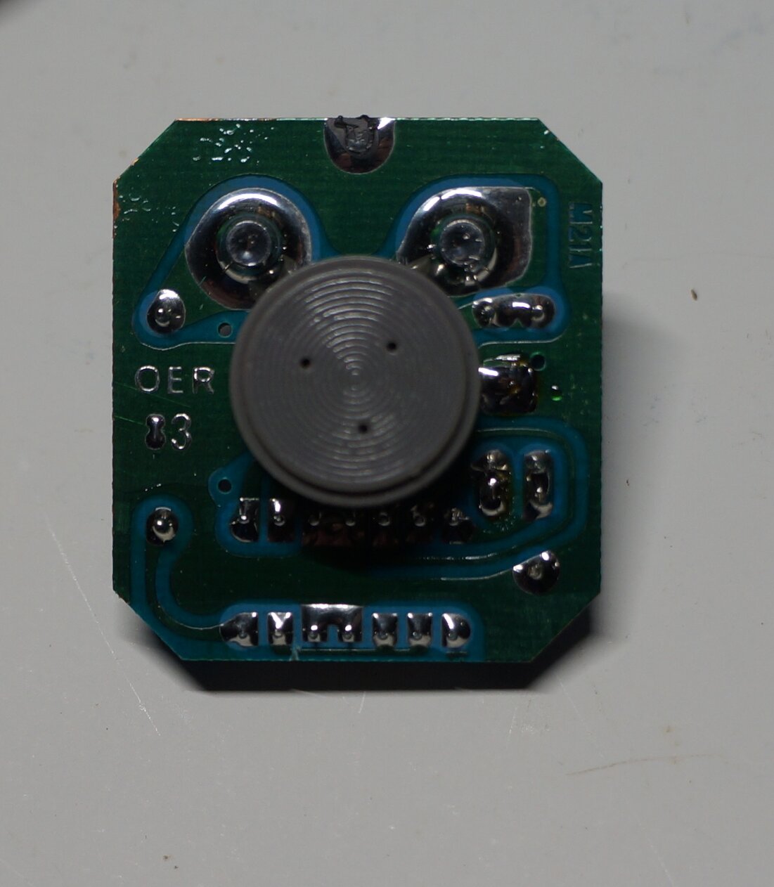
Track side and microphone.
BPO 332AT.
This article was inspired by a reader of
this site who had purchased a series 300 telephone, which he wanted to
use on the NBN. I explained the connections required for a line cord fitted
with an RJ plug, and also the need for a Dialgizmo.
With the phone now functional, there were complaints from the called (or
calling) party about weak voice. With their age and long term use, which
series 300 telephones have had up until now, I suspected the No. 13 transmitter
was probably at fault. One option I suggested was to obtain another No.
13 transmitter and see if there was any improvement. There is not really
a lot else that can go wrong.
I had also seen a well written article
concerning installing an electronic transmitter insert into a series 300
telephone. See the article here https://www.britishtelephones.com/tranchan.htm
It was of British origin, and explained how to adapt a No. 21A electronic
insert. Such inserts were available on the UK eBay, and it was decided
to go down this path. The installation was successful, and the problem
was solved.
The reader very kindly offered me a 21A
to try for myself, and hence this article. First, we need to learn about
the handset and how the transmitter is connected.
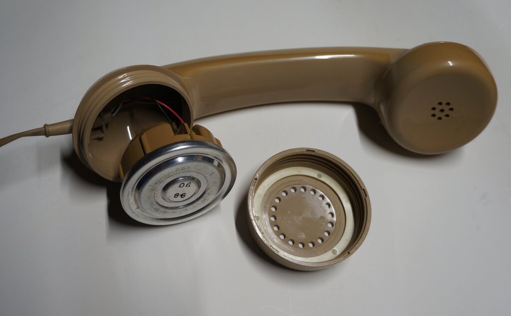
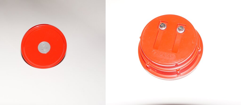
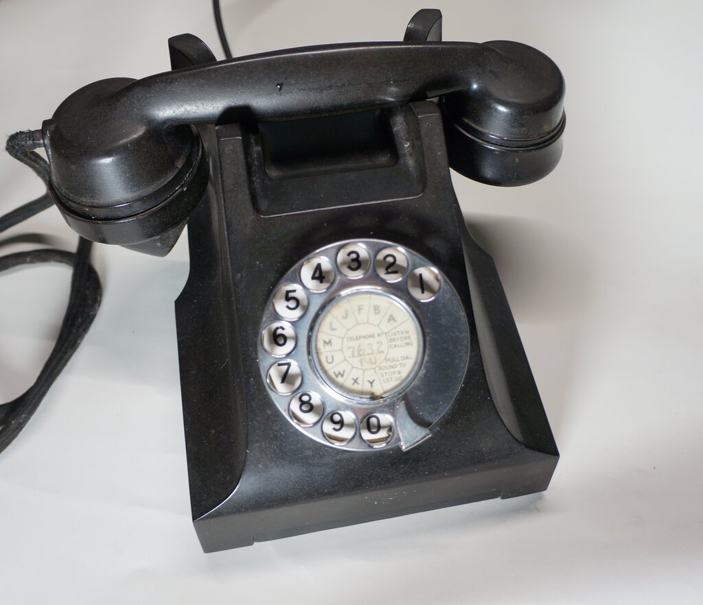
Handsets.
One of two types of handset will be found
on the series 300 telephone. These are types 164 and 184. Externally, they
appear the same, and the difference is in the connections. For the 164
handset, one transmitter terminal is common to one of the receiver terminals,
and is designated "MR" (Microphone Receiver). A three wire handset cord
is therefore used. In the case of the 184 handset, both receiver and transmitter
terminals are separate. This handset is used for instruments where there
is no common connection between the two. However, for the series 300 telephone
a strap is connected between terminals M1 and R2, to create the common
MR connection. In both handsets "R" designates receiver, and "M" transmitter
(microphone).
Connections for 164 handset at left, and 184 at right.
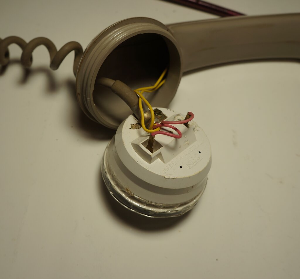
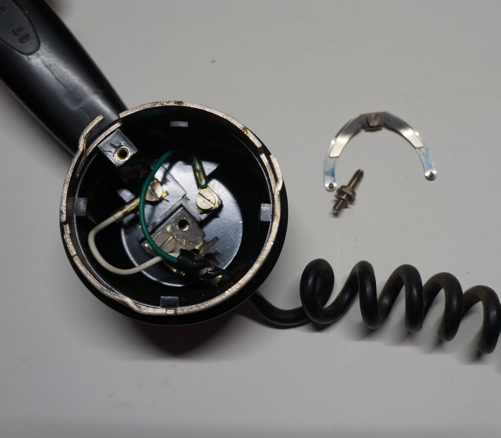
Two types of cord will also be found. Fabric covered cords were initially used, and these were later replaced by coiled PVC cords. In some instances, a line cord has been used as a handset cord. The later coiled PVC cord appears to have only a white and green wire, but in fact, the brass lug which secures the cord to the handset is the connection for the red wire. Non-coiled cords are self explanatory, since all three conductors are immediately obvious.
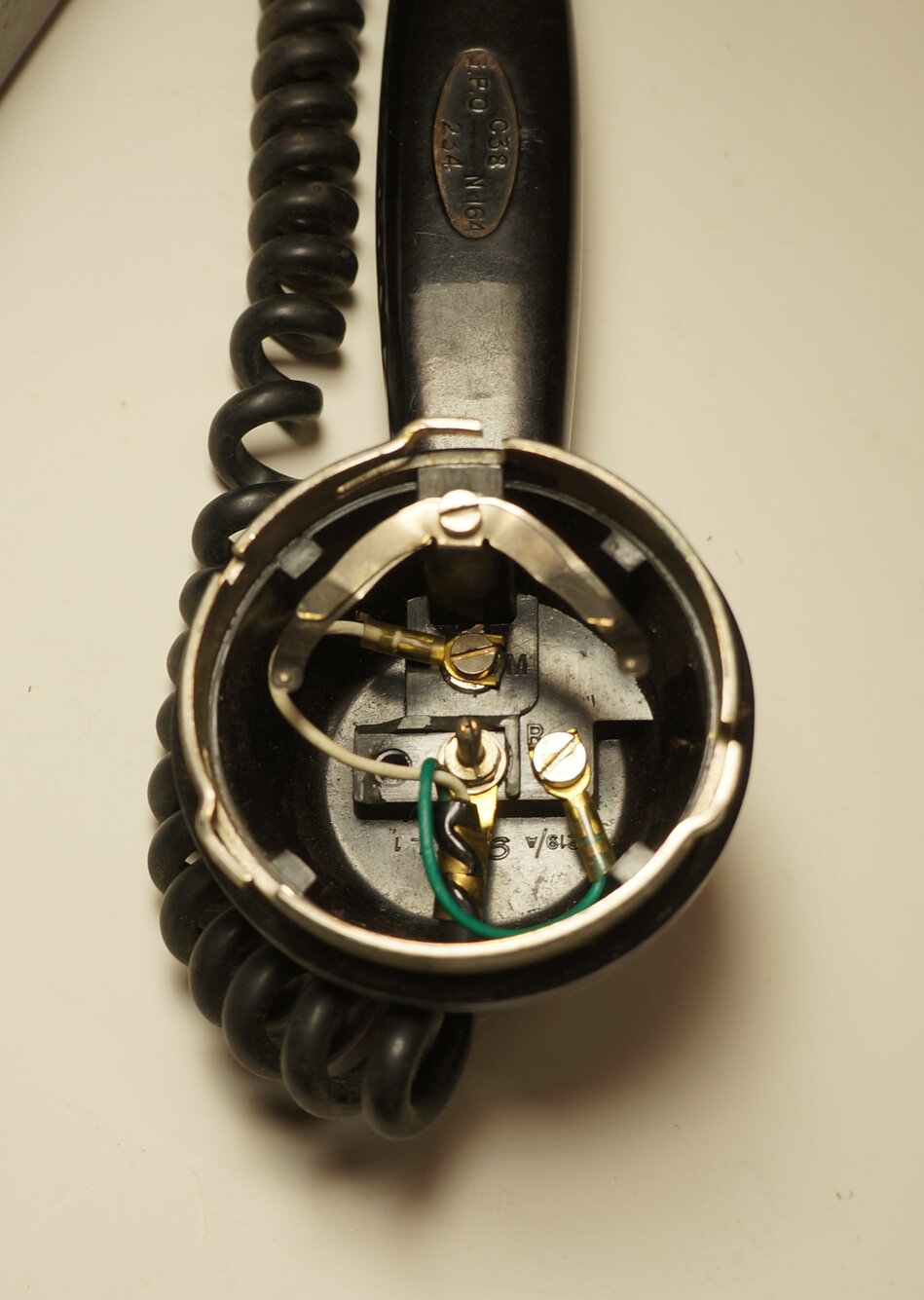
To remove the transmitter, to gain access
to the connections, requires turning the transmitter cap anticlockwise
from the front. However, there is a latch which has to be disengaged first.
Insert a suitable object, such as jeweller's screwdriver or nail,
into the hole.
Push down while turning the cap anticlockwise.
Once free, the transmitter is simply lifted out.
Push in latch slightly while turning the transmitter cap anticlockwise.
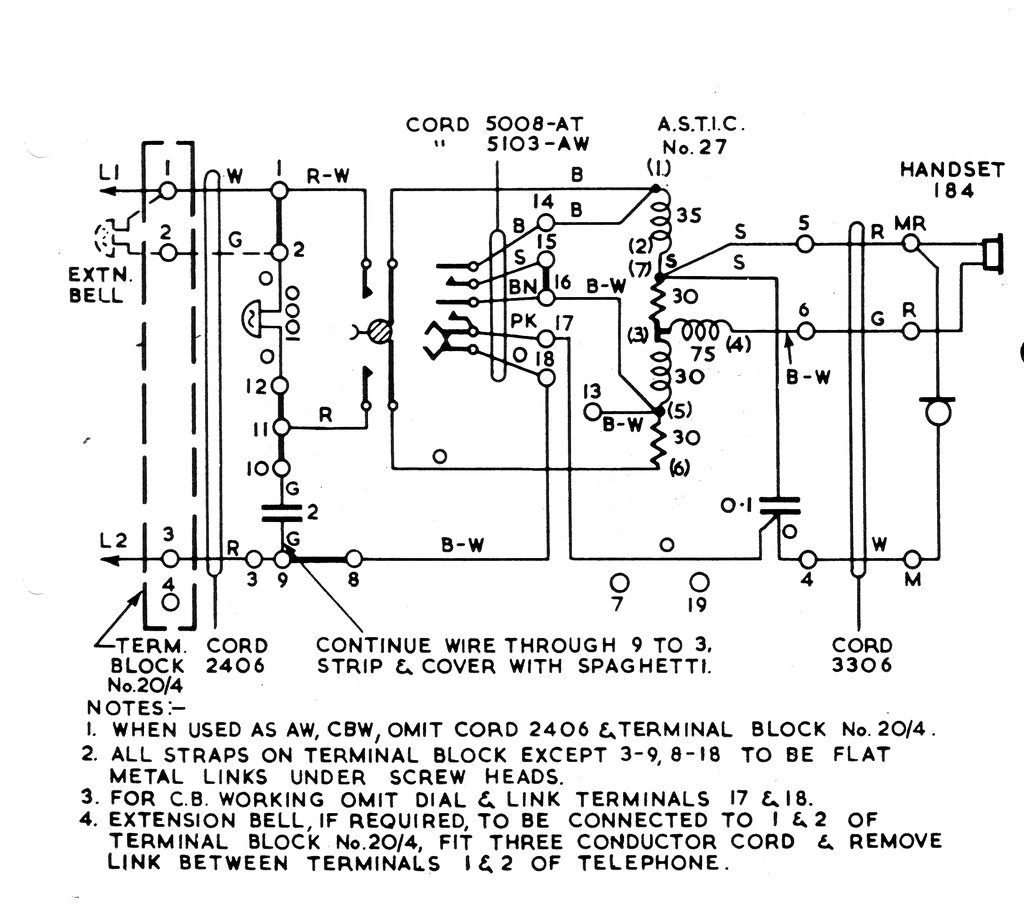
Circuit of the Australian series 300 telephone. Note the common
transmitter & receiver connection, MR.
Handset Wiring.
Before installing the electronic transmitter,
it's worthwhile to check the handset connections and colour coding. There
have been instances of the red and white wires transposed where a 184 handset
has been fitted with a coiled cord. This is because the pin which makes
connection to the centre terminal of the transmitter is the MR terminal
in the 164, but is the M2 terminal in the 184.
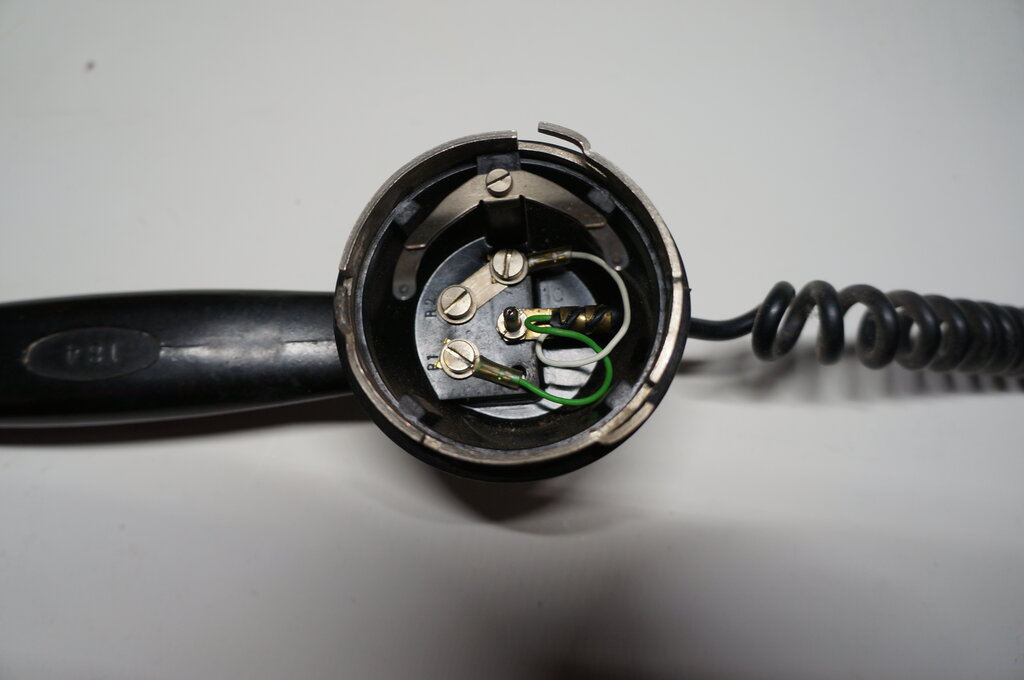
White and red wires swapped in a 184 handset, so that the brass
cord anchorage lug is still under the centre pin. At the instrument terminals,
the wires should be accordingly swapped, with red on terminal 4 and white
on terminal 5.
The termination of the coiled cord is such
that physically the red wire is permanently connected to this centre pin.
That is, unless the brass cord anchorage lug is shifted over to the R2-M1
link, which has also been done.
The point is the wire colours might not
match the circuit diagram, but as long as the connections are correct at
both ends, it does not matter. In the modern day, phones from second hand
sources have sometimes had strange things to them, and it's wise to check
first.
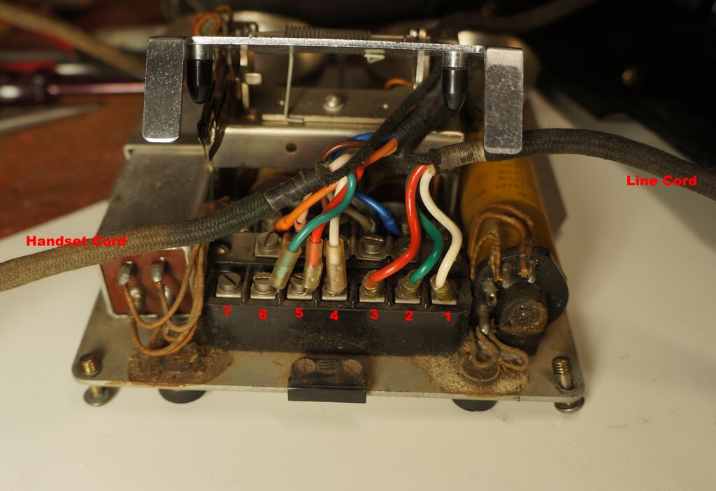
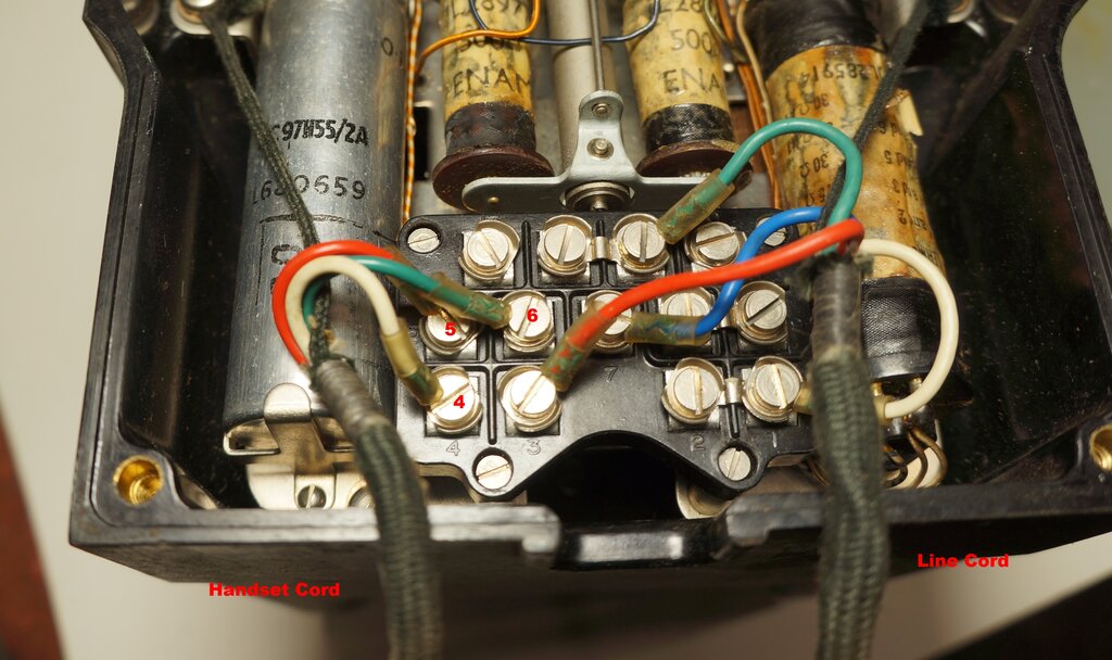
Connections for line and handset cords for the APO series 300 telephone.
The line cord connections may differ, 1) depending on whether the phone
is used singularly or in parallel with others, or 2) if a later line cord
with a 603 plug has been fitted - the colour coding was changed for these.
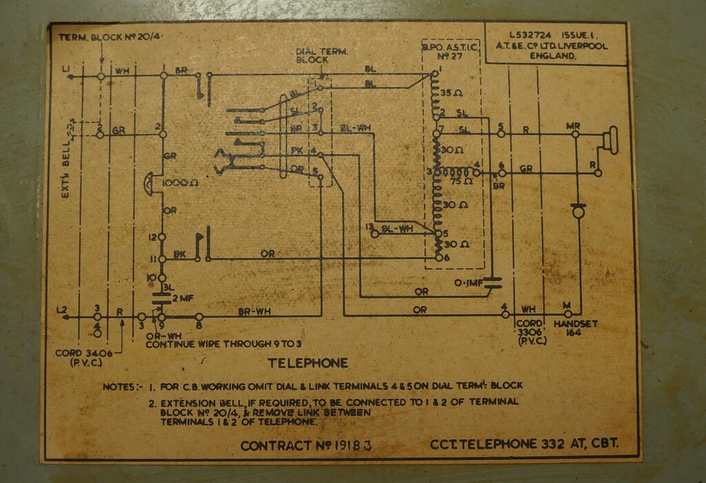
Circuit for the BPO 332. In some instances terminal 3 is blank and
the L2 connection is made directly to terminal 9.
Handset connections for the BPO 332. The line cord connections in
this instance are set up for parallel working as a second phone.
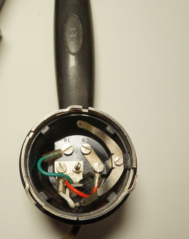
Regardless of whether the handset is a 164 or 184, the contact springs
and pin are removed.
Next, remove the screw from "M" and use it to secure the MR terminal (the little metal plate) from where the pin was previously removed.
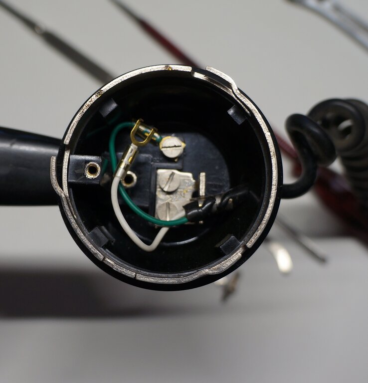
Centre pin replaced with screw from M transmitter connection. White
wire will connect to 21A transmitter.
Installing the 21A Transmitter.
Next, the 21A transmitter needs to be
modified. The red enclosure must be opened by unclipping it. Then extract
the black transmitter module. Connect it to the white wire, and with another
piece of wire, to the MR terminal.
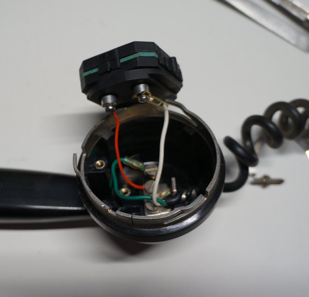
21A module connected to white (M) and red (MR) wires.
Now cut out a piece of foam, 30mm x 30mm x 20mm and use it for packing behind the module.
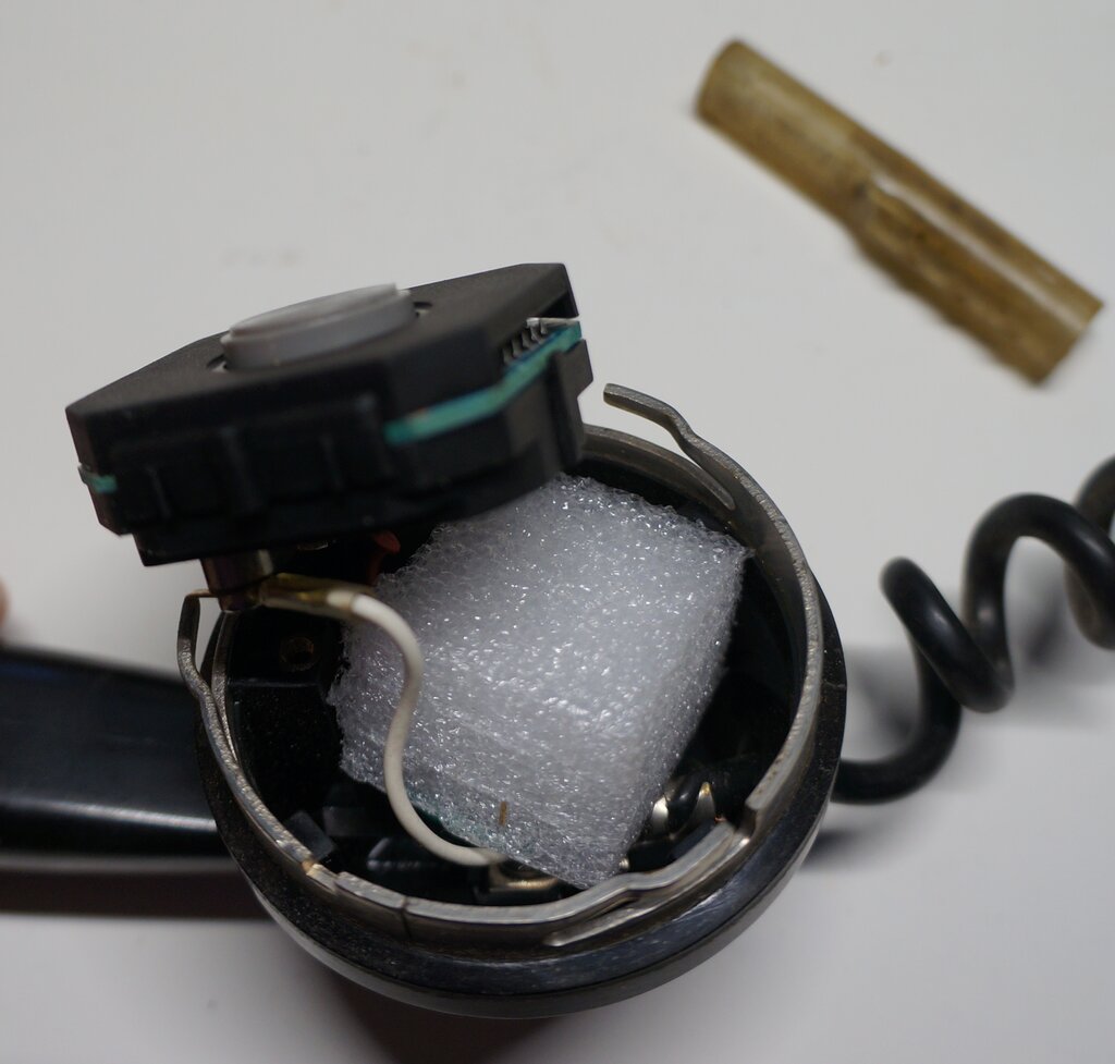
Foam keeps module located correctly and prevents connections shorting
out.
Position module so the side lugs are positioned as above, otherwise
it will not be able to sit centrally.
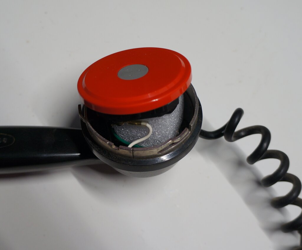
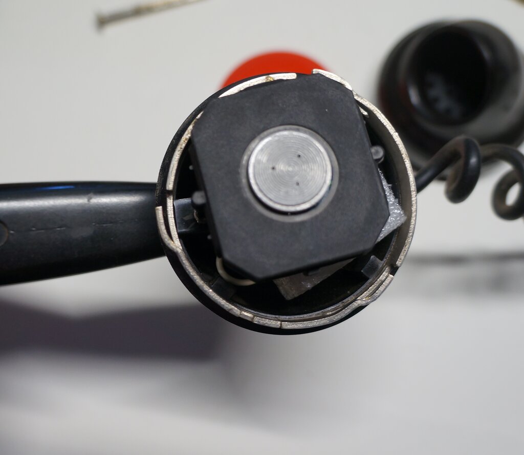
Sit plastic disc back on module and replace transmitter cap.
With a little bit of dexterity, the 21A module and the red cap are held in position while the transmitter cap is replaced. The job is done!
184 Handset.
The same procedure is used for the 184
handset, in that the centre pin is removed and replaced with a screw, and
the transmitter contact springs are removed. Since the centre pin is removed,
the screw to replace it can be the one adjacent on the little metal plate.
If the little metal plate is not there (as in the previous photo of the
184 handset with reversed colour coding), the screw can be taken from the
end of the strap which connects to the M1 terminal, since this terminal
connects to the springs which have been removed.
In short, the particular handset will
have to be studied, given the various ways it may have been connected to
the cord.
As previously mentioned, check the colour
coding to see if the red and white wires have been reversed, particularly
where a coiled cord is used.
Magneto Telephones.
The 21A transmitter is designed for central
battery and automatic telephones. Since its supply voltage needs to be
up around 5V at least, it will not work on the usual 3V battery used with
magneto telephones. However, in theory, adding an extra cell or two (4.5-6V)
should enable it to work. No experiments have been done in this regard,
but if one attempts it, make sure the current is not excessive - see data.
50mA would appear to be a suitable current.