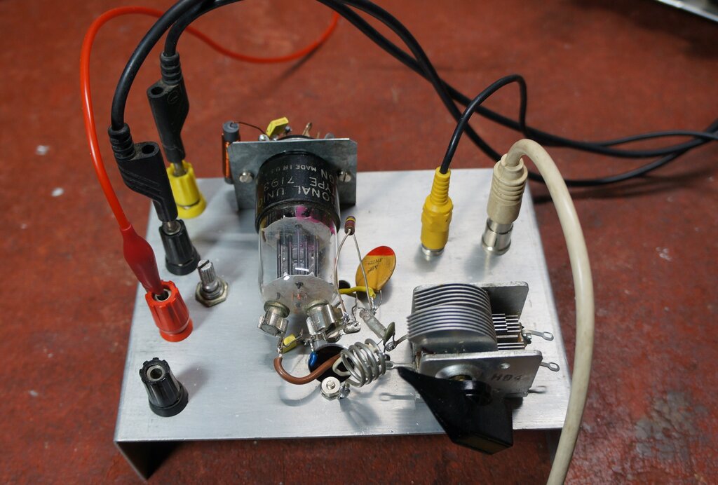
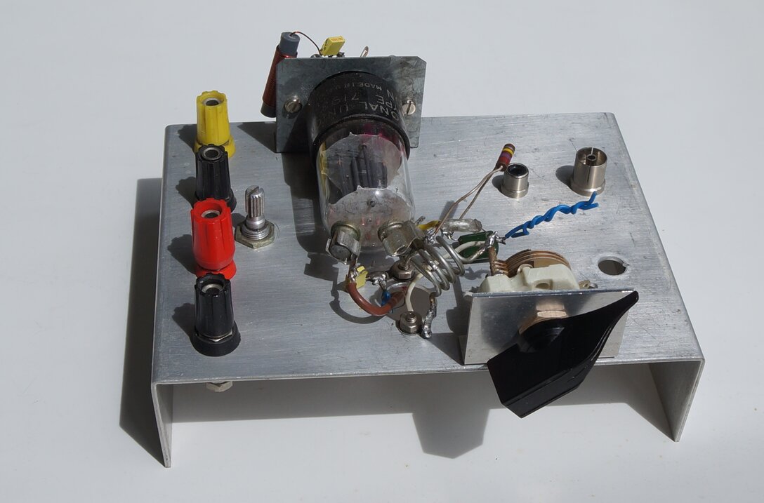
Test chassis with the 7193 VHF receiver.
Test chassis with the 7193 VHF receiver.
The 7193 is a relatively unusual, though
not particularly rare, valve. It was released in WW2 for military applications;
in particular for VHF service. As such, it does not appear in consumer
equipment, or in most valve data manuals.
My first encounter with the 7193 was with
a BC-966 IFF set, which contained three of them. For the 157-187Mc/s band,
one functioned as a transmitter, and the other as a super-regenerative
receiver. For the 211Mc/s band, the third 7193 functioned both as transmitter
and receiver. Both super-regenerative detectors were separately quenched
with a 320Kc/s oscillator.
The 7193 is also known as the 2C22. A
very similar British valve is the DET20, also known as VR135 or CV6. These
valves always stick out like the proverbial, because of being an octal
valve with two top caps. Heater requirements are 6.3V at 300mA for the
7193/2C22, and 6.3V at 200mA for the DET20/VR135/CV6. See here http://www.r-type.org/exhib/aab0148.htm
Another valve which appears to be virtually
the same, is the E1148 or VT-232. This valve is notable in that the triode
is mounted horizontally inside the envelope. I have never seen one for
real, but mention of it is made here http://www.r-type.org/exhib/acl0172.htm
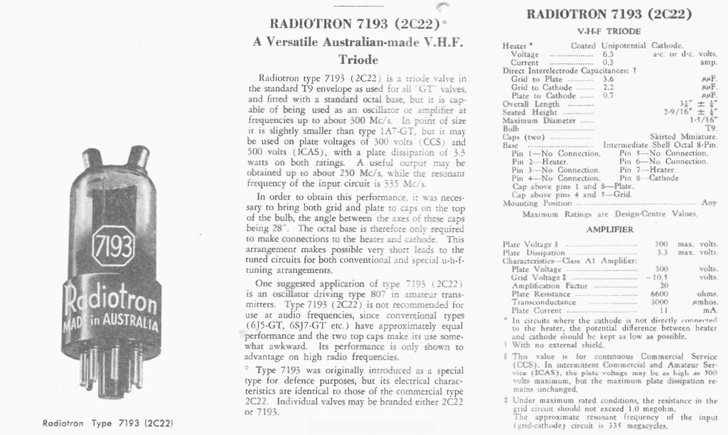
Data from AWV Radiotronics issue 117.
For some time, I had thought of an "all
octal" early 1940's style receiver for VHF FM. The thought of the lossy
bakelite base and long wires through the glass pinch to the valve electrodes
made me hesitant to go down this path with ordinary valves. However, the
7193 and equivalents are designed for VHF, and thoughts had
for some time turned to this valve, since I had some in my collection.
The 7193 is simply a 6J5 triode, but with
plate and grid leads brought to top cap connections. This avoids the problems
of lossy base connections, with the cathode connection apparently less
critical. Unfortunately, the audiophool brigade has latched onto this valve
and bumped up its price, with the thought of using it where 6J5's or 6SN7's
are specified. A 6SN7 is of course, two 6J5's in the same envelope. In
fact, adaptors have become available to substitute a pair of 7193's for
a 6SN7. Not only is this physically unweildy, but the long wires to reach
from the base to the top caps will have some capacitive coupling to each
other. Of course, modern day valve audio is all about emotion and appearance,
rather than good electrical design.
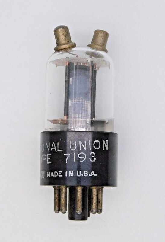
The 7193 looks unusal with its two top caps, but is really a 6J5
inside.
So, what type of circuit would suit the
7193? Usually, it is used with the type of oscillator circuit that I dislike;
that is, with both ends of the tuning condenser (and coil) live at RF.
Not only does the tuning condenser need an isolated mounting and shaft,
it also needs isolation from hand capacitance. The other choice is a dual
gang tuning condenser, in which case the body can be earthed. Neither
are particularly convenient.

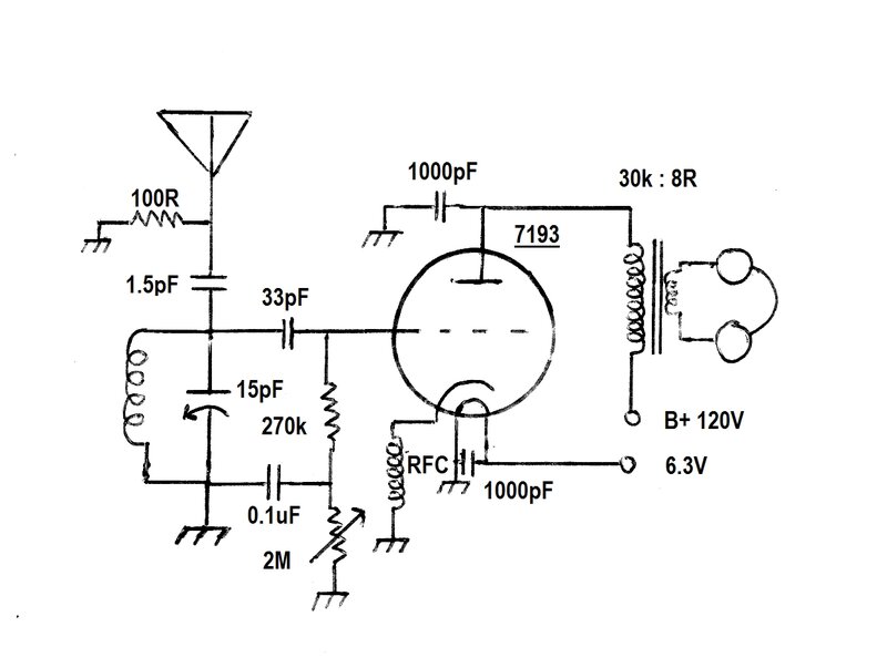
Typical of many published circuits, this design has many shortcomings.
Apart from the live tuning capacitor, the method of regeneration control
does not provide full sensitivity, and there is no quench filtering for
the audio amplifier.
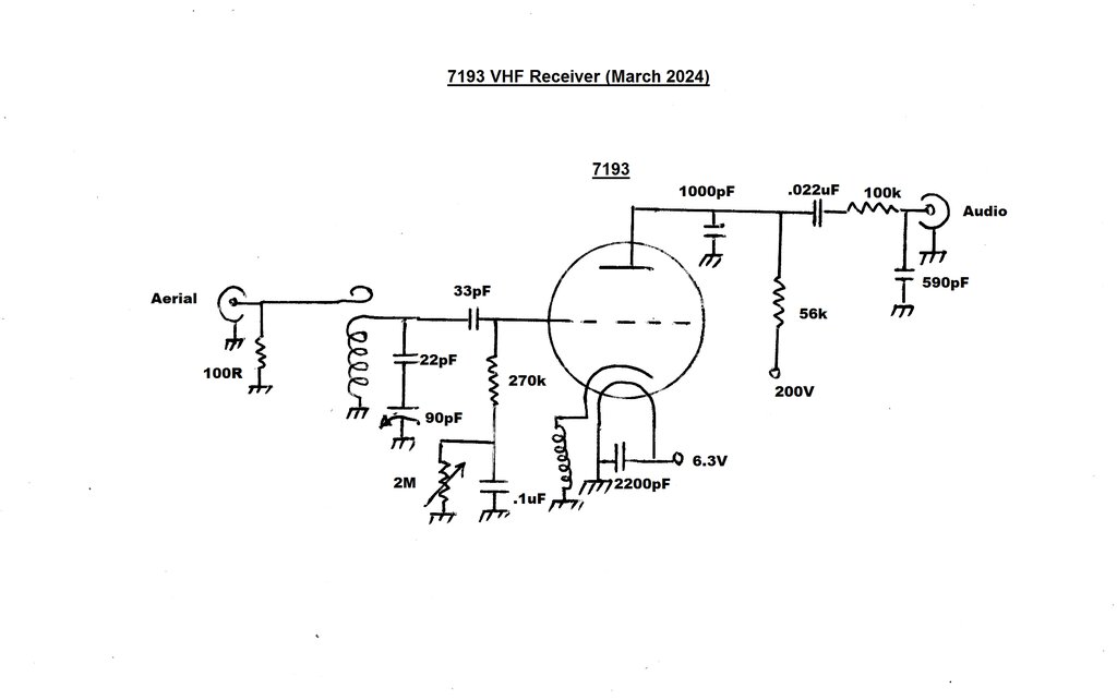
My preferred circuit is a modification
of the Colpitts oscillator, which is simple and effective. Both one side
of the tuning condenser and oscillator coil are earthed. It has been used
in most of my valve VHF receivers.
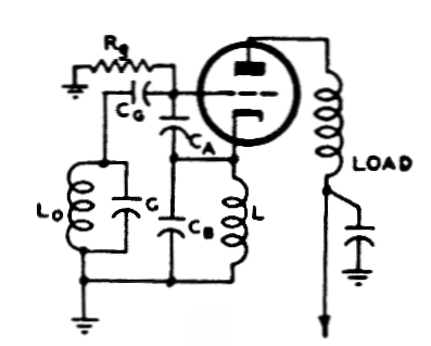
This version of the Colpitts oscillator allows one side of the tuning
coil and condenser to be earthed.
Capacitors CA and CB are not always physical
capacitors, but may be the grid to cathode capacitance inside the valve,
and the self-capacitance of the choke, respectively. L is an RF choke suited
to the frequency of oscillation, and LO and C forms the usual tuned circuit.
The question is, since the cathode is
required to be live at VHF, how would this go with the long wires of the
bakelite base? As it turned out, rather well...
Those who have already seen my improved
6C4 receiver, may recognise a striking similarity. This is not surprising,
because the 7193 is similar to the 6C4, in that both are medium mu triodes
(u=20). The difference is in the construction, because of the two top caps
at one end of the valve. Incidentally, in the modern day, PC mount 3AG
fuse clips make ideal top cap connectors for the 7193 and other valves.
The aerial (or strictly speaking, oscillator)
coil is the usual four turns of 1.6mm tinned copper wire, air cored, 10mm
diameter. 1.6mm is close to 14 gauge in both AWG and B&S. However,
a gauge or two either way is not important.
This coil should be tuned with a 15pF
variable condenser, for the 88-108Mc/s VHF FM band. Since I have plenty
of 90pf variable condensers, in the form of the oscillator section of a
MSP (AWA) medium wave tuning condenser, I used one of those instead.
A 22pF ceramic condenser is connected
in series to provide something like the correct tuning range. While this
certainly works, the tuning across the band is not linear. Stations at
the 108Mc/s end are closer together than at the 88Mc/s end. Also note that
MW tuning condensers are not designed for VHF. This was evident with some
bearing noise as the condenser was adjusted. A proper VHF tuning condenser
has phosphor bronze wipers to the shaft at several points, to bypass current
flowing through the ball bearings.
To cause the circuit to oscillate, a quarter
wave choke is connected between the 7193 cathode and earth. This too has
been described many times on this site. 75cm of 26 gauge wire is wound
on a 6.3mm plastic former. Again, a gauge either way, or a slight change
in diameter is not important. The cathode choke suited the method of construction
for this receiver well, since the other alternative; a connection from
the cathode to a coil tapping, was seen as impractical because of the length
required.
Because of the physical attributes of
the 7193, it was thought best to install it on its side, since this would
keep the connections to the tuned circuit as short as possible. If the
valve was in the usual upright position, the tuning condenser and coil
would have to be on a panel at the same height as the top of the valve.
There's no objection to this of course, but since there is no such panel
on the test chassis, it was constructed as seen in the introductory photo.
Quenching occurs because of the time constant formed by the grid condenser (33pF) and resistor (270k). Quench frequency is about 27kc/s. As stated elsewhere on the site, the greatest audio output occurs with the lowest quench frequency. However, there are practical limits, and too low of a quench frequency causes obvious intermodulation distortion, particularly with music. Taken even lower, it becomes audible all the time as a tone in the background. Increasing the quench frequency improves the sound quality, but reduces the output level. Initially, the grid resistor was 180k which gave a quench frequency of 48kc/s. Output was much increased when this was lowered to 27kc/s by changing to a 270k resistor. Much lower than this begins to cause problems with the beat of the 19kc/s stereo pilot tone against the quench oscillator.
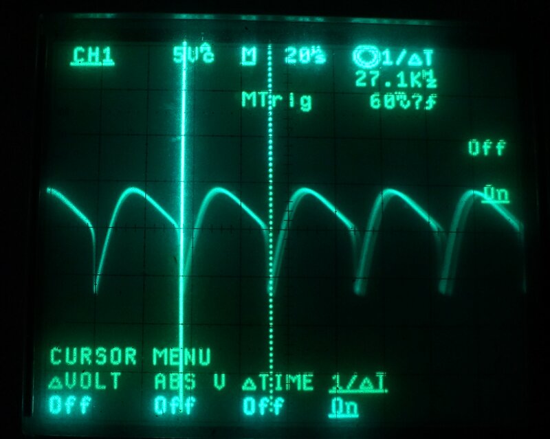
Measured at the plate, quench frequency is 27.1kc/s.
Regeneration Control.
The amount of regeneration needs to be
adjustable. Most published circuits simply vary the B+ to the plate circuit.
Unfortunately, while this appears to control regeneration, sensitivity
is always poor.
More sensitivity is obtained by adjusting
the grid voltage instead. Remember, a super-regenerative detector works
by triggering the oscillator on the incoming RF signal. By taking the grid
voltage as close to cut off as possible, before oscillation stops, the
oscillator is at its easiest point to trigger. Most published circuits
seem to operate with an excessive amount of oscillation anyway, which only
adds to the difficulty of triggering difficult on small signals. These
are the circuits where you see a 10M resistor from the B+ to the grid.
The fact that such designs provide a nice loud rushing sound deludes their
designers into thinking they have a sensitive receiver. This
receiver is a classic example of poor design.
If you've seen the other super-regenerative
circuits around this site, you'll see a variety of methods for adjusting
the grid voltage. A cathode rheostat is one, where raising the cathode
DC voltage above earth creates the same voltage, but negative, on the grid.
A separate source of negative DC may be fed in directly through the grid
resistor. Of late, a simpler method I have used is to use the actual rectified
voltage from the grid. I first used this method with the 6GK5
receiver.
As the circuit oscillates, negative voltage
appears at the grid because of the diode formed between grid and cathode.
If the grid resistor is high enough, the voltage will become so negative
that the valve cuts off. In this circuit, the 2M rheostat provides this
adjustment. But, on its own that would cause a very low quench frequency
with the full 2M in circuit. We need to keep the quench frequency constant
as the 2M rheostat is adjusted. This is where the 0.1uF comes in. As far
as the quench oscillation is concerned, the grid resistor is always 270k,
because the bottom of it is AC earthed via the 0.1uF.
Any of the regeneration control methods
can be used with this circuit. A separate variable negative supply fed
into the bottom of the 270k resistor will give a sharper oscillation cut
off if preferred. This is because it is not possible to fully cut off the
oscillation using rectified grid voltage alone. The reason is obvious -
with the circuit not oscillating, there is no negative voltage generated
in order to cut it off. In practice, there is no advantage between the
methods as far as sensitivity is concerned.
The regeneration control will also adjust the quench frequency within narrow limits. This is useful if intermodulation distortion is problematic with particular program material.
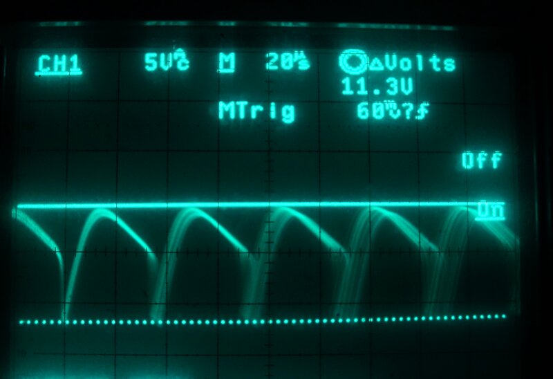
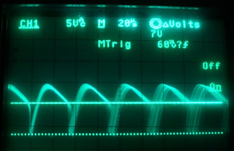
Plate waveform showing the voltage levels. These show what to expect
for correct operation.
**Update Re
Grid Voltage Control**
The method of using the grid leak voltage
as the actual regeneration control voltage works well, and simplifies the
circuit. However, it does not provide complete cut-off. For 'normal' reception
this is not important, and indeed, the self regulating feature is convenient,
and appreciated by less technical users. Where utmost sensitivity is required,
the adjustment range needs to be able to take the detector just out of
oscillation. Therefore, for any kind of 'DX' type of receiver, the grid
resistor should be taken to a variable negative voltage supply instead.
Plate Circuit.
Some experimentation was done with plate
voltage and the plate load resistor. Initially I used 82k for the plate
resistor. This worked well with a B+ of 180V, but much better results were
had with 280V. For a lot of receiver designs, 280V of filtered DC is not
always convenient.
The receiver also needs to work at no
more than about 200V. The other super-regenerative receivers described
on this site work at around 150V. In this regard, better performance was
obtained with a 56k plate load. It's no coincidence this is the same value
that suits the 6C4 receiver.
To compare B+ and plate loads, the following
output voltages were obtained. The receiver was fed with a 20uV AM signal
at 103.5Mc/s, modulated to 50%.
| B+ | Plate Load | Audio Output |
| 150V | 56k | 543mVp-p |
| 200V | 56k | 836mVp-p |
| 150V | 82k | 571mVp-p |
| 200V | 82k | 774mVp-p |
As can be seen, with the choice of 150V or 200V B+, most output occurs with 200V and a 56k plate resistor.
Quench filtering is the standard circuit
I've used before. The 100k and 590pF remove a considerable amount of the
quench frequency. If not removed, the following audio amplifier will be
overloaded, restricting audio output. 590pF is a strange value, but is
what I had to hand. 560pF is close enough, or use a 470pF and 150k resistor
instead if more convenient. The values are not super critical, with the
resistor being 100k to 150k and the capacitor being 470pF to 1000pF. Ideally,
the capacitor should be the highest value that does not cause unpleasant
loss of treble.
Ideally, the best filtering is active,
such as the Sallen-Key circuit I used with the mains
operated 12AT7 receiver. This provides a much sharper cut off frequency,
and if your receiver can accommodate two extra triodes, is well worth it.
As always, the intended load is a 500k
or 1M volume control, which precedes the following audio circuit. A 1M
volume control will give slightly greater output, since less voltage will
be dropped across the preceding 100k - 150k filter resistor.
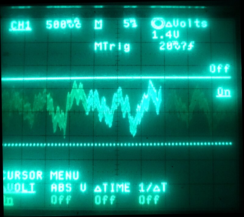
The thickness of the audio output waveform is due to the supersonic
quench signal.
Transformer Coupling.
Using an audio transformer instead of
a plate resistor did allow lower B+, but sound quality was poor. On that
note, a 30k speaker transformer driving low impedance headphones, however,
did provide good results with 100V B+. The speaker transformer was simply
substituted for the plate resistor, and the 1000pF plate bypass was retained.
The other components were of course not required. See the 6J6
receiver to see how it's done. The only thing to take note of is that
the DC resistance of the transformer is low, and plate current could be
excessive, if the B+ is too high and/or the circuit stops oscillating.
Aerial Coupling.
Simple light capacitive coupling to the
aerial coil was used. As found with the 6C4 receiver, even 1.5pF coupling
is too much, and oscillation becomes difficult. This is because these medium
mu triodes don't oscillate as actively as higher mu types like the 6ES8
or 6GK5.
All that is required is a loop of wire
placed close to, or in between turns of the coil, and this connects to
the external aerial. You can just see a piece of white wire pushed in between
the coil turns in the photo of the prototype. You can also see this method
of coupling with the 6C4
receiver. A 100R resistor provides some initial load, so that the aerial
sees something like the correct impedance, and so the receiver is less
affected by aerial loading. A capacitive plate near the active end of the
aerial coil would also be suitable. The idea is to get the most coupling
before the circuit oscillates unreliably over part of the band.
No doubt, a second 7193 could be used
as a grounded grid amplifier, and the various 12AT7 circuits show how to
implement this.
Performance.
It works just like all the other single
triode (no RF amplifier) designs. 10uV will give listenable results, with
30uV being fairly noise free. 3uV could be heard, but was definitely not
of entertainment value.
If you have some 7193 valves looking for
a use, this is an ideal project for them. Of course, with a minor modification
to the tuned circuit, the receiver will cover the aircraft band.
Seeing how successful this circuit has
been, it would appear possible to use a 7193 as a converter in a pulse
counting FM receiver, with a following IF amplifier also using octal valves.
The third method; adjusting the cathode
voltage with a rheostat alone, is similar to the second method, except
there is no bleed current through the potentiometer. The potentiometer
needs to be a higher value of resistance to get the same voltage drop,
since the current is from the cathode alone. This method saves one resistor,
and decreases the B+ current consumption compared to the 2nd method.
At the time of developing this control
method, it was thought there would be a degree of automatic regulation.
If the oscillation was excessive, the cathode current would be high, the
voltage drop across the rheostat would increase, thus increasing the negative
grid voltage, and reducing the oscillation.
The fourth method was developed as a simplification of the first method, but without requiring a separate negative supply - something which is not always convenient. The idea was since the grid voltage is negative when the valve is oscillating, if this voltage was filtered into pure DC, it could be used as the source of variable negative voltage. It worked very well, and has been used with many of the later circuits presented. It was then realised that this method too would provided a degree of automatic regulation. If loading, etc. reduced the oscillation, the negative DC would decrease, which would then cause an increase in oscillation.
Whilst studying the operation of the Fremodyne receiver, it turned out that by coincidence, what I had independently developed was actually the same method of automatic stabilisation used in that circuit. However, unlike the Fremodyne, I had not used both stabilising circuits together.
The 7193 receiver was a convenient test bed for some further experiments. One thing I was curious about was the cathode RC circuit for generating the quench frequency used by the Fremodyne. How well would it work at 100Mc/s instead of 21.75Mc/s? It worked very well actually. Both stabilising circuits were tested together and also worked well, as did taking the audio from the cathode. Essentially, the super-regenerator from the Fremodyne had been used, but with my favoured modified Colpitts oscillator, directly on the 88-108Mc/s band.
There was one catch, however. While the quench frequency is set by the RC time constant, this varies considerably with the cathode current. The result was that there was a considerable variation of quench frequency as the receiver was tuned across the band.
It is well to remember that the super-regenerative detector in the Fremodyne operates on only one frequency! To cut a long story short, having to readjust the quench from one end of the band to the other did not allow the user adjustable control to be eliminated, in this instance.
However, going back to my quench circuit
using the RC time constant of the grid circuit, this is much less dependent
on cathode current, and quench frequency varied by only about 2kc/s across
the band.
The end result seemed to be that the grid
stabilisation is more effective than that of the cathode, and the Fremodyne
press release does mention that.
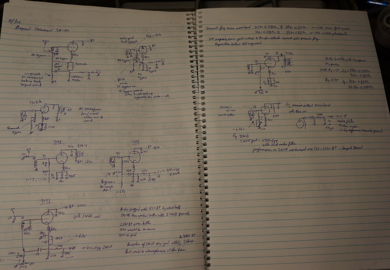
Experiments performed on the 7193 receiver. These may be presented
at a later date in a practical form.
Ceramic Tuning Condenser.
A considerable improvement was gained
by replacing the MW tuning condenser with a proper ceramic VHF type. The
intermittent, and sometimes low oscillation across the band was gone at
last. Also, the correct tuning condenser allowed the 22pF padding condenser
to be eliminated. Ideally, the capacitance should be a maximum of 15 to
20pF. The type I used is from 4.7pF to 32pF. The frequency coverage is
therefore still greater than required, but could probably be reduced by
taking a turn off the coil. This has not yet been tried.
It would appear the stabising circuit
works better with the increased oscillation. With the receiver tuned in
to 2NUR (10kW, 135km distant), and the B+ set to 200V, the voltage could
change from 190V to 250V with no change in performance, or any need to
retune. Output voltage was roughly 700mV p-p.
A further improvement was had by adding a second section for the quench filter. The single section filter can only remove so much quench before the loss of treble becomes obvious. By having a two section filter, the roll off is sharper. I used 100k and 470pF for the second section, which was feeding a 1M amplifier input resistance.
Ceramic VHF tuning condenser has been a major improvement and made
this a very nice receiver. Note 1.5pF gimmick capacitor behind tuning condenser.
In view of the improved oscillation with the ceramic tuning condenser, it was also possible to provide for tighter aerial coupling, using a 1.5pf capacitor to the top of the oscillator coil. With the tighter coupling, it was found best to keep the B+ up around 240-250V, although there is no problem with it oscillating at 190V. The volume is noticeably better at the higher voltage.
Headphone Receiver.
In its simplest form, headphones can be
driven from the 7193 super-regenerative circuit.
About the simplest practical receiver for VHF FM.
The circuit is an adaptation of that which
has already been described, but instead of the 56k plate load resistor
is an audio transformer feeding the headphones. This transformer can be
of the type used for P.A. speaker line matching.
In view of the transformer load, it is
best to keep the B+ below 120V. This is because if the valve stops oscillating
there is nothing to limit the current except the transformer DC resistance,
and the maximum current that can flow through the triode with no bias.
Even with 120V, the maximum current that
flows is about 15mA which is a little above the rated 11mA, but harmless
in the short term. When operating normally, the B+ current draw is only
about 1mA. Performance drops off below about 110V, and more suitable valve
types would be required for lower voltages. Although it was not tested,
it might be possible to increase the B+, by including a current limiting
resistor and bypass capacitor. The resistor will drop minimal voltage when
the valve is oscillating, but limit the current to a safe value should
it stop.
As with other super-regenerative receivers, reception is possible in strong signal areas with just the signal pick up from the oscillator coil. The external aerial, 1.5pF, and 100 ohm can thus be dispensed with, further simplifying the receiver.