In 1969 National commenced assembling TV
sets in Australia. The factory was a 20 acre site located in Penrith on
the western outskirts of Sydney. The sets were Japanese models adapted
for Australian conditions. In this regard, the modifications were along
the same lines as General Electric's adaptations of U.S. designed sets,
which were manufactured and sold in Australia, such as this
one. National products were already being sold in Australia, being
imported by Haco, and this continued, with only the Televisions being a
separate entity.
National's parent company was Matsushita
Electric. In the U.S. the company was known as Panasonic, to avoid confusion
with their long established National radio company. In the rest of the
world, the National brand was used up until the 1988, when it became Panasonic
worldwide.
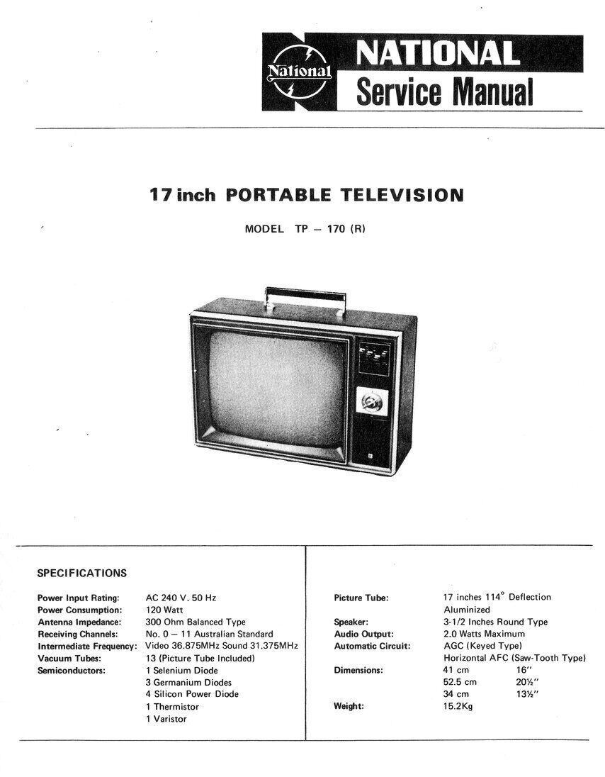
The first series of National TV sets assembled in Australia were valve monochrome designs. Initially, there was a range of 25" lowboy sets; TC-510, TW-520, TW-521 and TL-530. The TW-520 was available with a cassette player fitted as model TW-520C. Finally, there was the 24" TL-240 lowboy. Then came three portables; the 12" TP120R, the 17" TP170R, and the 20" TP200R. From here on, sets were solid state, and colour production started in 1974.
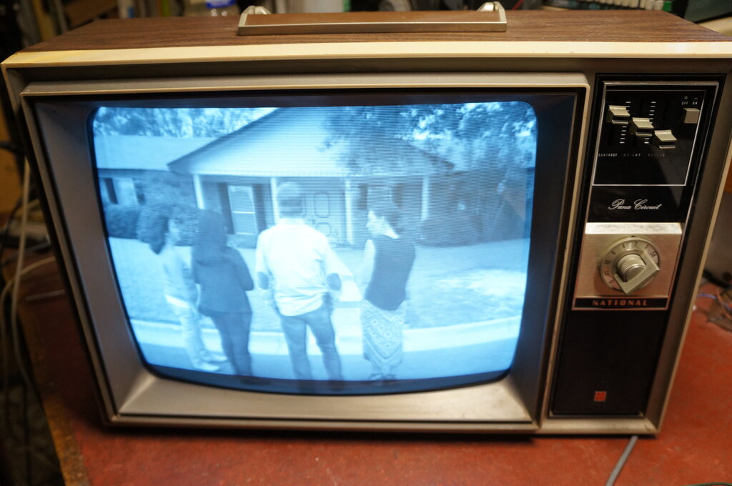
The TP-170R.
I have two TP-170R's in my collection.
One came from a friend in the mid 1980's. It had been bought in a second
hand shop and used in their holiday house. The second set was found in
a council cleanup in 2001. It had attached to it a tag from the David Jones
"Appliance Centre" (an upmarket department store in Sydney), which suggests
the set may have been serviced by them. The first set still has all original
components and is functional.
This shows just how reliable Japanese
components were. The second set turned out to be quite different, and is
the set to be described here.
It appears that for part of the production, National elected to use locally made IRC resistors - and this is what I found in the second set. When National started TV manufacturing in Australia, the policy was 50% local production. The lowboy cabinets were made locally. It would appear that the IRC resistors were to help fill the 50% quota. Indeed, my TW-520 has an Australian made CRT. The set was inoperative when I got it, and once I took the back off and saw the IRC resistors, I can't say I was surprised why it didn't work. All my other National sets have Japanese resistors, and this is the only one I've seen with the IRC resistors. The problem is that Australian made IRC resistors are notoriously unreliable, with the values usually drifting high. It's quite possible that National realised this and returned to the Japanese resistors later in production. Until recently, it was mainly resistors over about 47k that were drifting high, but as time has gone by I am finding that even very low values are now drifting. Restoring vintage electronics is no longer just a matter of replacing paper capacitors - the micas are also suspect, as are any IRC carbon resistors.
Australian Modifications.
Like virtually all Japanese/U.S. valve
portable TV designs of the 1960's-70's, the National sets use series heater
valves. One of these is a Compactron, for the line output/damper valve.
However, for Australian production, an isolating step down transformer
is used to power the set. As has been mentioned elsewhere, live chassis
sets were "not the done thing" in Australia, and the few models that did
appear were criticised by conservative types, who couldn't seem to grasp
that the rest of the world didn't have a problem with them.
As usual, the UHF tuner has been omitted, since at the time there were no actual plans in Australia for UHF television. The tuner is fitted with all 13 Australian VHF channels, and the channel knob labelled as such. Some foreign designed sets appeared in Australia with European channels, since the systems are identical. These sets could not receive channels 3,4,5 and 5A since these are unique to Australia, so were of limited used outside capital cities.
Of course, being of Japanese design, and also being sold in the U.S., the set was originally intended for 525 line 60 field operation running off 100V (Japan) or 120V (U.S). The 625 line 50 field system is so close that few, if any, modifications need to be done to the deflection circuits. The line frequency is so close that no modifications need doing (15,625 c/s vs. 15,734 c/s). Usually, there is more than enough adjustment with the frame hold control that the frame circuit needs no modifications when operating at 50 c/s instead of 60 c/s. It's just possible that the linearity correction circuit might need a slight modification, but again there's usually enough adjustment.
The most important change is the sound IF, with Japan and the U.S. using 4.5Mc/s instead of the Australian (and European) 5.5Mc/s. Also, the video IF amplifier response needs to be adjusted for the wider bandwidth, for the alignment to be correct. And, finally, the choice of video IF should, in theory, be that of the local standard to avoid any interference problems. In practice, sets sold here have used the European video IF of 38.9Mc/s or the old U.S. standard of 20Mc/s without any problems. The National uses the correct Australian video IF of 36.875Mc/s.
The Circuit.
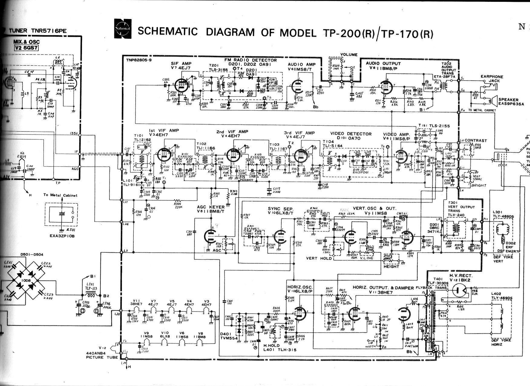
There is a mistake on the circuit concerning the AGC keyer triode.
See description for details.
Most of the set is constructed on a PCB, mounted on a steel chassis. This in turn is mounted on the cabinet bottom by two nylon insulators - these being a legacy of the live chassis original. This chassis, along with the steel cabinet, and the locally fitted power transformer make it a heavy set to carry, at 15.2kg.
Video IF.
The video IF amplifier is based around
two 4EH7's and a 4EJ7. These are the 450mA series heater version of the
6EH7 and 6EJ7 respectively. These are frame grid pentodes, and it's notable
that it's a three stage IF amplifier, since these frame grid valves are
normally used with a two stage amplifier. This comes about because the
frame grid design provides a higher gain than conventional pentodes. On
that basis, it should be more sensitive than the average set. The circuit
is conventional with double tuned transformers, and traps at the input
circuit. Video detection is solid state with an 0A70 germanium diode.
Video Amplifier.
A unique Japanese valve is used here,
the pentode section of an 11MS8. As far as I can tell, the 11MS8 was designed
by Matsushita Electric, and I have only ever seen it in National sets.
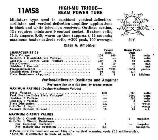
The 11MS8 appears to be a development
of the 6GV8/ECL85. The pin connections are the same and the characteristics
are similar, although not identical. The 11MS8 has slightly higher gain
for both the triode and pentode. Unlike the 10GV8 (LCL85) which would be
the closest equivalent, the 11MS8 does not have a European type number.
It is also notable that what was intended as a frame output valve is being
used as a video amplifier.
As for the video amplifier circuit itself, it's entirely conventional, being AC coupled to the CRT. Contrast control is the high level type, being a potentiometer in the plate circuit. This has the advantage that the sync separator is always fed with the highest possible amplitude video signal, regardless of contrast control setting. The disadvantage is that the more the pot wiper is moved away from the plate connection, the more resistance there is in circuit, and the more it is affected by stray capacitance. Therefore, circuit layout is important and usually some frequency compensation is required. Also in the plate circuit is the sound IF take off transformer, tuned to 5.5Mc/s. This also functions as a sound trap since its impedance is highest at 5.5Mc/s.
Sound IF and Detector.
Another 4EJ7 is used as the 5.5Mc/s sound
IF amplifier. It feeds a ratio detector transformer and thence two 0A91
diodes in a ratio detector circuit. The circuit is entirely conventional.
The 4EJ7 is operating as a normal class A amplifier, rather than a limiter,
since the ratio detector provides sufficient AM rejection.
Audio Amplifier.
From the ratio detector, the signal passes
to the triode of the previously mentioned 11MS8. What is perhaps unusual
is that the volume control is not at the input to the triode, but between
it and the output pentode; this being an 11BM8/LCL82 - the 450mA heater
version of the well known 6BM8. This operates with a slightly low cathode
resistor (150R), but by passing a bleed current through the cathode resistor
(via three series 6.8k resistors), the cathode voltage is increased to
what it should be. Why this was done is open to a few possibilities. In
some circuits this has been done because of cost cutting. That is, by using
a low value cathode resistor, less signal is lost across it in terms of
negative feedback, and so the usual associated electrolytic capacitor can
be dispensed with. The bleed resistor required to restore the cathode voltage
is cheaper than an electrolytic. Pedantic? Yes, but it's interesting just
how far some manufacturers will go to cut costs. Another scenario is that
the designer wanted some cathode feedback to improve sound quality, but
the normal value of resistor would be too high, reducing the gain too much.
By reducing the resistor to provide the right amount of feedback, the DC
conditions have to be restored with the bleed resistor.
Notice that the triode of the 11MS8 first
audio amplifier is operating with quite a high value of unbypassed cathode
resistor. This suggests the designer thought there was ample gain in the
audio amplifier.
The audio output is operating from the
unfiltered B+ and it's an interesting thought that the bleed resistor might
actually help cancel out hum, since the cathode is in phase with the plate.
From the 11BM8 pentode, the signal passes
through the output transformer and then into a 4" speaker via an earphone
socket. The 47R resistor protects the earphone against excessive input
power and also reduces the hum level.
Sync Separator.
Back to the unusual valve types, here
we have a 6LX8/LCF802. This is the 450mA series heater version of the 6JW8/ECF802.
There is only 20mA heater current difference between the two types, but
importantly, the 6LX8 has controlled warm up time; important for series
circuits. One could no doubt use a 6JW8 as a replacement with a 330R shunt
resistor, if the 6LX8 was impossible to get.
The circuit is conventional, with the
usual input components to improve the wave shape of the incoming video
signal. What is different is that the grid is returned to B+ through a
10M resistor, rather than the usual 1M or thereabouts, resistor to earth.
Presumably the clipping is more effective with the grid slightly positive.
The plate load is 27k, across which the sync pulses are developed. The
line and frame sync pulses are then separated with their respective filter
circuits. The frame pulses are filtered out by the low pass filter, comprised
of R351 and the associated encapsulated circuit, X302, before being fed
into the frame oscillator.
Line sync is filtered out by C401, acting
as a high pass filter. This passes the 15,625c/s line pulses while greatly
attenuating the 50c/s frame pulses.
Frame Oscillator and Output.
Apart from another 11MS8, the circuit
here is again conventional. It is a triode and pentode connected as a multivibrator,
with the pentode being the output in the usual way. Using this configuration
saves on having to use a blocking oscillator transformer, or an additional
triode. Since the height and linearity controls are within the oscillator's
feedback loop, the field frequency is affected by the adjustment of these
controls. Setting up the height and linearity with this circuit might also
require adjustment of the frame hold. Closer examination of the circuit
shows a 12M resistor (R359) between the wiper of the height control and
the wiper of the brightness control. This provides height compensation
as the brightness is adjusted. Normally, as brightness is increased the
EHT voltage falls. This in turn causes the picture to expand, because it
becomes easier to deflect the electron beam from the CRT cathode. To counteract
this, the height is reduced as the brightness adjustment is increased.
Line oscillator.
This is a Colpitts oscillator using the
pentode of the 6LX8, which is what this valve was specifically designed
for. It is also curious that the grid is returned to B+ through a high
value (5.6M) resistor, rather than to earth in the usual way. A point of
interest is that the plate load is fed from the B+ boost supply. Obviously,
this is done to obtain a higher drive to the line output pentode, as the
normal B+ in this set is only 135V
As is usual with negative modulation systems,
the line oscillator is controlled by an AFC circuit. This is the purpose
of the dual diode D401. Frequency of the 6LX8 is controlled by the DC grid
voltage; not the individual line sync pulses. The diodes compare the phase
of the sync pulses against the pulses from the line oscillator (via the
output stage and line output transformer). If they are not the same frequency,
a correction voltage is developed by the diodes so that the oscillator
is pulled back to the correct frequency. Because this correction voltage
has a time constant long enough to block out individual sync pulses, it
means the oscillator is given a degree of noise immunity.
Line Output.
A 38HE7 Compactron provides both the line
output and damper diode functions. This is a higher power version of the
33GY7. For a set with 110 degree deflection, the circuit is simple. There
is no VDR stabilisation or adjustable linearity correction. Width is adjusted
simply by a tapped screen grid resistor. EHT is rectified by a 1BK2.
AGC.
A conventional gated or keyed AGC circuit
is used here, using the triode section of the 11BM8. This triode operates
as a variable diode, rectifying pulses from an additional winding on the
line output transformer. As the triode conduction increases, so does the
negative DC produced at the plate. It is a shunt rectifier circuit, with
the pulses fed in by C301. The plate is decoupled from the filter capacitor
(C302) by R302. The triode conduction is in turn controlled by the video
signal. Part of the video amplifier plate current passes through the AGC
preset, R301. The voltage developed across this feeds the triode grid.
Note at this point there is a mistake in the circuit. As shown,
the 11BM8 triode grid would be damaged and R301 would burn out, because
B+ would be flowing to the grid via R301 and then to earth via the cathode.
The mistake, if you've not yet worked it out, is that the triode cathode
returns to B+, not earth.
Since the triode plate current only flows
at the line frequency, and provided the phasing of the pulses from the
line output circuit are suitably adjusted, the point at which the triode
conducts is only during the line sync interval. The amount of conduction
is dependent therefore, on the video signal level only during the line
sync period.
Hence, the main advantage of the gated
AGC circuit is that it acts only on sync pulses and not the actual luminance
signal. This means that the AGC is not affected by picture information,
but is reliant only on the true signal strength. Another advantage is that
by operating at line frequency, the time constant of the filter can be
made short, so that the system is fast acting and can deal with rapid signal
fading. Simple AGC circuits require a long time constant to filter out
the lowest frequency of picture information (50c/s), and cannot act as
quickly.
Furthermore, the gated AGC circuit is
effectively amplified. That is to say, the control voltage available is
much higher, since it comes from the line output circuit. A simple AGC
circuit is limited to the negative voltage peak from the detector diode;
typically about -3V.
AGC is applied to the two 4EH7's and the
tuner RF amplifier. Note that 4EH7 is a variable-mu valve which is suitable
for AGC. 4EJ7 is a sharp cut off design, and not suited for AGC. This is
because taking the grid sufficiently negative to reduce the gain, will
cause the valve to operate in its non linear region, causing distortion
of the video signal. AGC to the tuner's RF amplifier is delayed by the
12M resistor, R306. This prevents the AGC acting on the RF amplifier until
the signal becomes sufficiently strong. Without it, the gain of the RF
amplifier would be reduced on very weak signals, since some AGC voltage
will be generated from noise. This in turn reduces the signal to noise
ratio when it's needed the most.
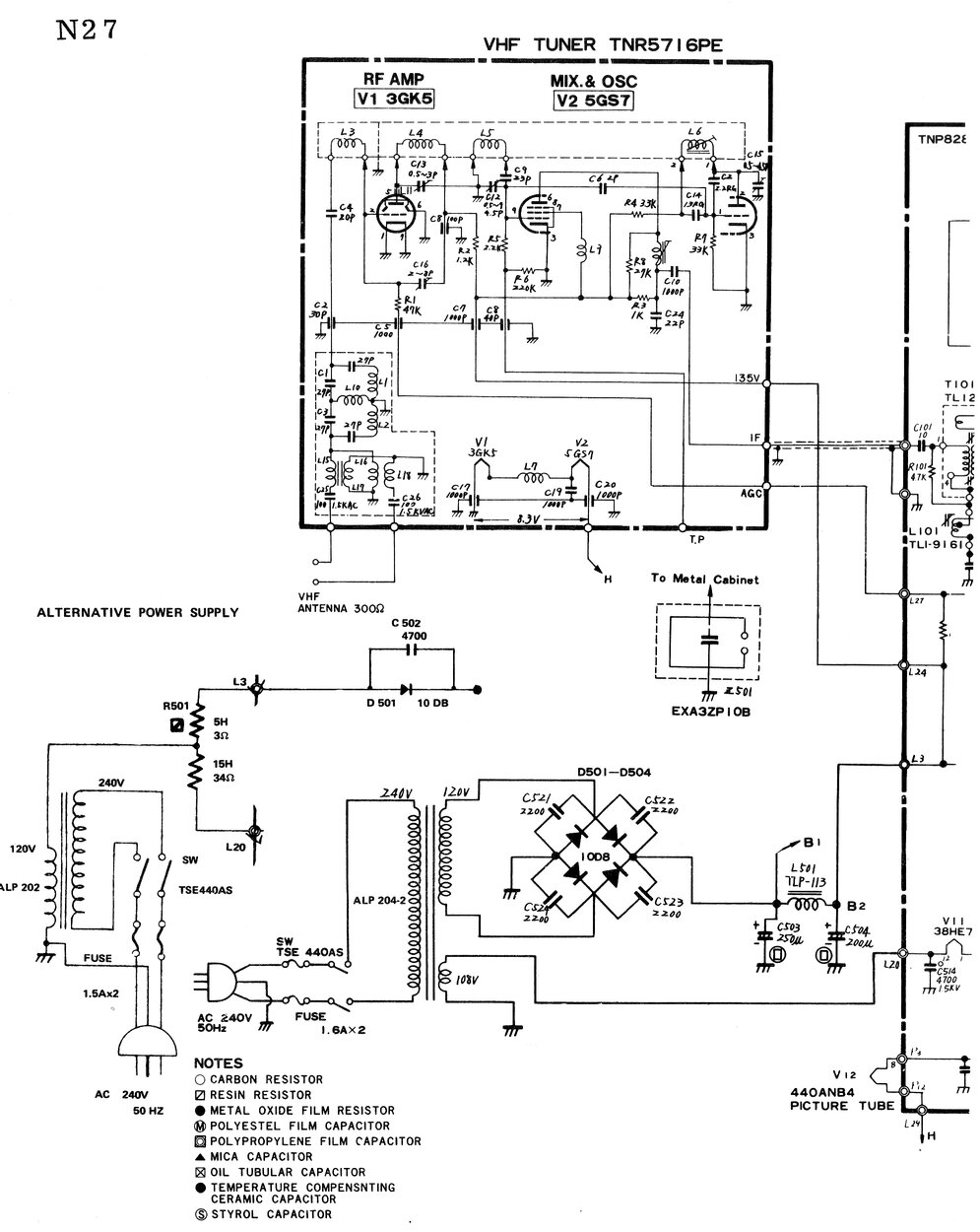
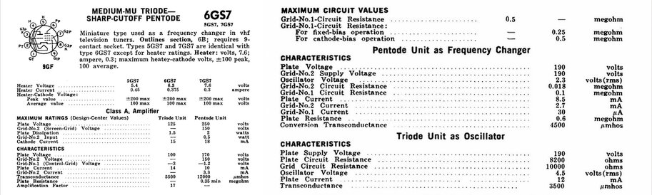
The tuner is a Matsushita TNR5716PE turret
type, using a 3GK5 RF amplifier and 5GS7 converter valve. It is a copy
of a U.S. designed Standard Kollsman tuner. These Matsushita clones have
also appeared in Thorn sets made in Australia. They have been used with
parallel heater valves (6GK5 and 6GS7), as shown here,
and for 300mA heater circuits (4GK5 and 7GS7) in the Thorn R2 and R2M.
The 3GK5 is a standard well known valve and needs no introduction. Some
description of it is available
here.
The RF amplifier is the usual neutralised
triode type. This feeds the pentode of the 5GS7 operating as a mixer. The
triode functions as the local oscillator. The 4/5/6GS7 valve is another
type like the 11MS8 that seems to be of Matsushita design, which has not
been found anywhere but in their tuners. It does not appear to be based
on any existing types, although the pin connections are the same as the
6CG8. From the data, it is a frame grid type.
Power Supply.
Two power supply circuits are shown. Both
of my TP170R's use the 120V transformer with full wave rectification, and
a separate 108V winding for the heater string. I also have a TP200R (which
uses the same chassis with a 20" CRT), but it uses the alternative where
a 120V transformer feeds a half wave rectifier for the B+, and the
heater string through a resistor. This is obviously closer to the original
design of these sets, and in fact the component locations for the half
wave rectifier circuit are on the PCB.
From an efficiency point of view, the
full wave rectifier is superior, in that there is no DC magnetisation in
the transformer, and of course B+ filtering is improved since the ripple
is 100c/s instead of 50c/s. Additionally, the heater dropper resistor is
eliminated, saving nearly 7W of heat being generated.
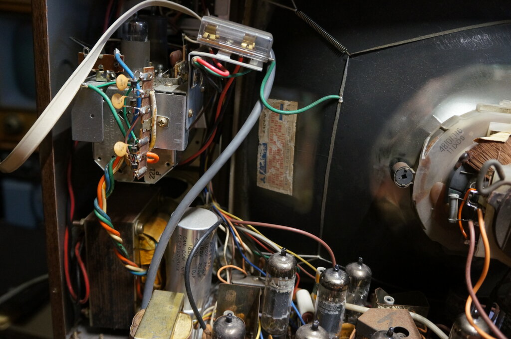
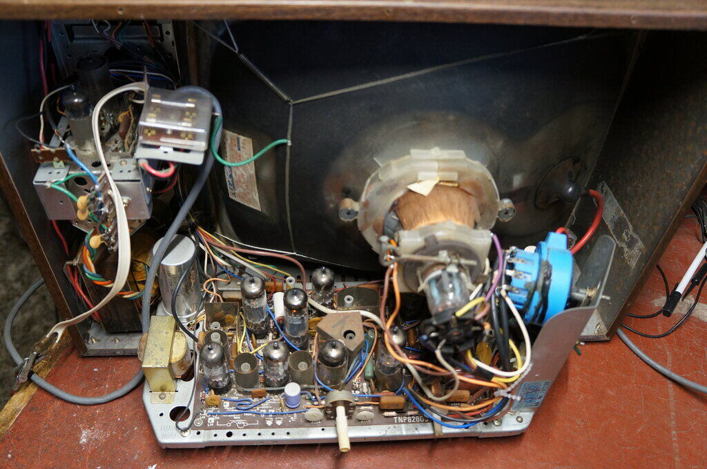
Transformer at bottom left. Fuses at top. Full wave rectifier is
mounted on the tagstrip on the back of the tuner. Notice the fuse bracket
is slightly bent.
It is a curiosity why both the incoming live and neutral are fused, when only a fuse in the live is required. The fuses have been mounted on a locally produced bracket screwed to the side of the tuner chassis. The power cord is terminated on this bracket, and the way it is positioned means the bracket bends if the mains cord is pulled on. There is no cable clamping where it enters the cabinet; only on the mains input bracket with the fuses. Both of my TP170R's have suffered this bent bracket; the other set to the point where the tuner mounting was deformed, causing the channel knob to rub against the front panel. Despite the otherwise good quality of the Australian modifications, it is surprising that this design fault exists.
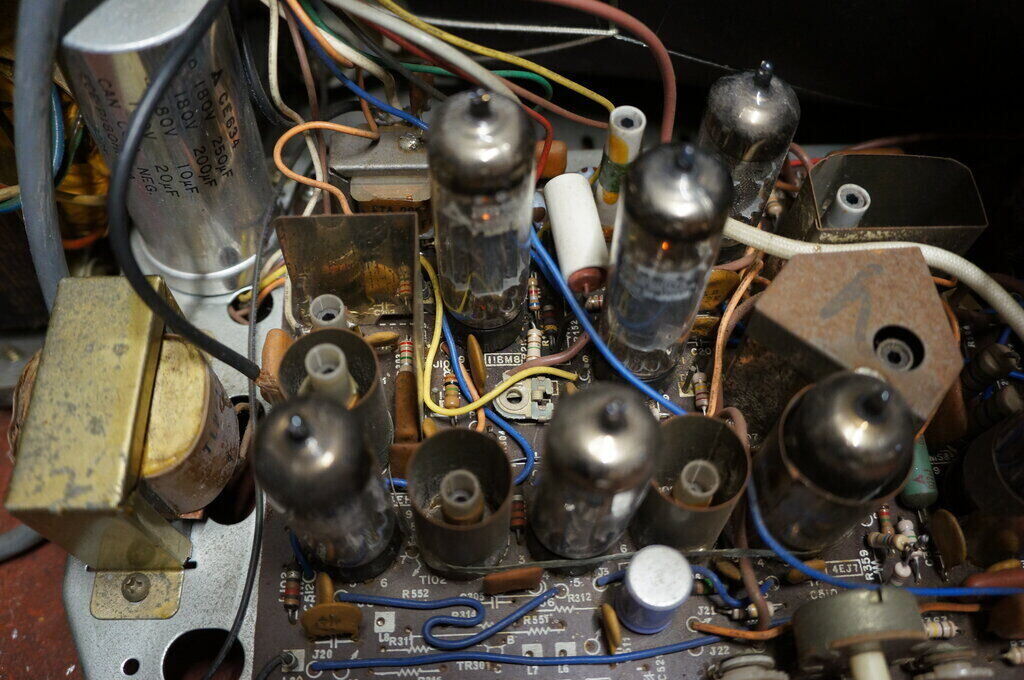
Notice the unoccupied component locations at the bottom of the PCB.
These are for the half wave rectifier version.
Shorted Yoke.
This set was relegated to my garage on
a specially built shelf, for viewing whilst working on the Model T. After
a few years the line deflection failed, and the 4.7k damping resistor R414
was burnt. The fault turned out to be shorted turns in the deflection yoke;
a problem that is starting to become uncomfortably common (no wonder I
like electrostatically deflected TV sets so much!). Part of the problem
is decomposing brown glue which becomes conductive, and eats through the
enamel insulation of the copper wire. Alternatively, some yokes; mostly
from the 70 and 90 degree era, have rubber insulation between the windings
which degrades and also becomes corrosive. A common problem with modern
colour sets is the rubber wedges used to position the yoke for convergence
adjustment. These also eat into the windings causing insulation failure.
Being a 110 degree CRT with standard neck,
there would be plenty of yokes that would physically fit, but the question
was getting a good electrical match. Otherwise, width and linearity suffer
with horizontal mismatch, and if the vertical section is mismatched, proper
height and linearity cannot be obtained. Altering the circuit to get an
acceptable picture only works to a small degree, and there is the risk
that the deflection valves can be operating outside their ratings. Things
are of course more critical with line deflection, because of the higher
frequency, and that the yoke affects the tuning of the line output stage.
I had good luck with a yoke from an AWA 50 series chassis. Vertically, it was an excellent match. Horizontally, it was not quite so, with reduced width and cramping on the right side. Simply connecting a 150pF 6kV capacitor across the outer connections fixed it, with normal width and acceptable linearity.
Lost Sync.
It worked fairly well for the next few
years, although there was a drift in the frame oscillator/output, in that
after operating for a while, the picture would become very non linear and
eventually lose frame hold.
Obviously a heat sensitive fault. Then
the set permanently lost both line and frame sync so I stopped using it
altogether.
Eventually, I got motivated to fix the
set properly, which is of course the subject of this article! To start
with, I replaced just about all the remaining IRC resistors. The one or
two left were very low values like 120R which I did test, and which were
in very non critical locations.
This didn't fix the sync however. First
suspect was the 6LX8, since there was plate voltage but hardly any sync
waveform. It tested ok, and just because it was easy to do, tried a 6JW8
in its socket. This confirmed it wasn't the valve. Seeing as we had a good
plate resistor, what about the grid resistor? It's 10M (R309) and with
a value like that is always suspect. Bridging it out with a multimeter
on the volts range (10M input resistance) restored operation. But hadn't
I replaced all the IRC resistors? Well, yes, but this was something else.
It looked like a high precision resistor of the type used in a multimeter.
I really can't remember if it was one I replaced in my original repair,
or if it was original, and not being IRC, overlooked it.
In any case, replacing it fixed that problem.
Next thing was the frame linearity changing
over time. It was much better now, but not as good as it should be. Seeing
as all the resistors had been replaced and there were no paper capacitors,
the 11MS8 was a suspect. Simply swapping it with the video 11MS8 confirmed
that it was the problem. The video 11MS8 has a much less arduous life than
that of the frame output, so this was no surprise. The 'defective' 11MS8
seemed to work happily as the video amplifier where things are less critical,
so that fixed that without having to replace any valves.
Yoke Replacement - again!
While the AWA yoke worked well, and I
highly recommend it, I have had for many years, the yoke from an unusual
NEC set. It was also 17" 110 degree, and was made for the South American
market, evident by the switch for 525 or 625 lines. The set had no back
on it, so never knew what model it was. It was also missing all its knobs
and two of the valves. It's a story for another time, but suffice to say,
it got pulled apart in the end. I still had the CRT with yoke attached.
Since they were both Japanese sets of the same era, I had often wondered
if the NEC yoke might be a better match, and not require the extra tuning
capacitor.
Now was the time to find out. And, yes,
the horizontal section turned out to be a perfect match. In fact the plastic
mouldings of both yokes looked very similar; almost identical unless one
looks very closely. Things were not so good with the frame coils though,
with severe lack of height. Turning up the height control was not enough,
with the result then being severe non linearity.
This lack of height suggested that the
impedance of the yoke was too high, since there wasn't enough voltage to
drive it fully. And why might that be? A close look confirmed what I suspected.
Anyone who works on vintage TV's and understands them, knows that each
yoke winding is actually two sections, so there are actually four separate
windings to operate on the four axes of deflection. If you haven't guess
it yet, it's because the original National yoke has the frame windings
connected in parallel. The NEC had them in series. I do actually have the
NEC frame output transformer, so could have used that to replace the one
in the National, but before that, let's try connected the windings in parallel.
And that was it. Full vertical deflection again. Linearity wasn't too good,
and I thought about modifying the circuit to fix that, but there was one
other thing left to examine. Good linearity could be had, but not quite
with full deflection. Seeing as there's a thermistor in series with the
vertical windings, I tried shorting it out. Now we had excellent linearity.
Presumably, because the yoke had series connected windings, the thermistor
could have a higher resistance than one for parallel windings. I didn't
even try the original National thermistor since the NEC yoke works so well
without it, and height drift as the set warms up isn't a problem.
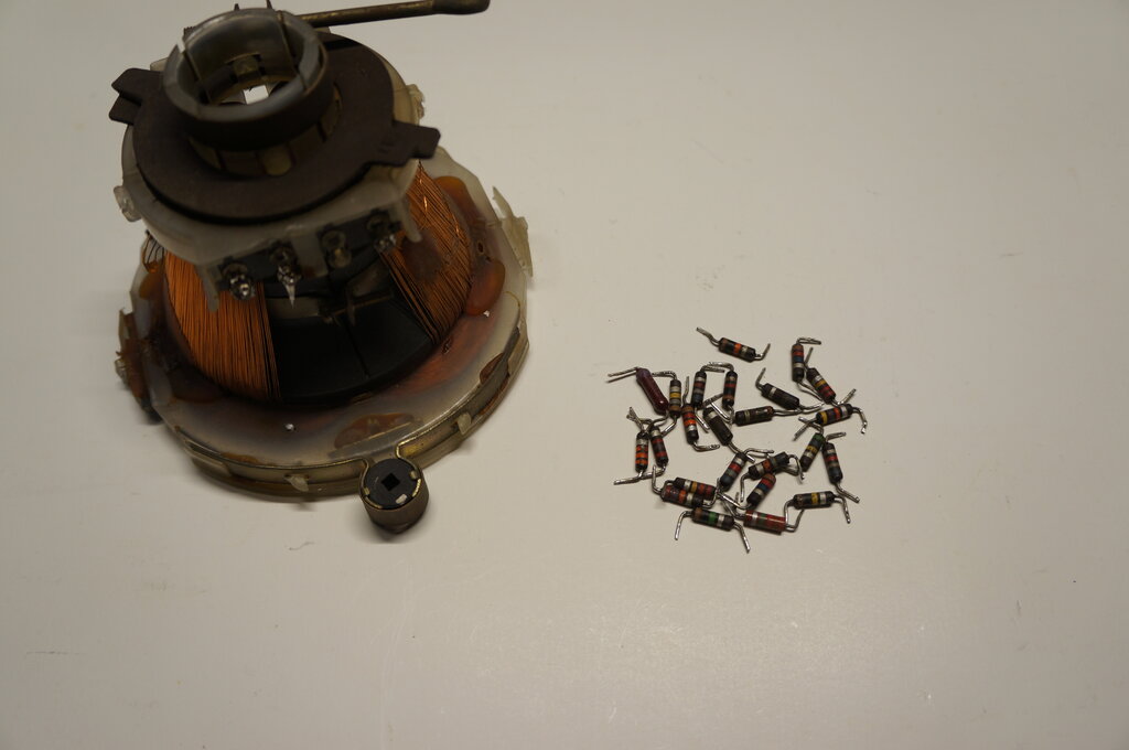
Original National yoke and the second lot of resistors replaced.
Not bad for a non original deflection yoke!
This set has a very good CRT, but for my other TP170R and TP120R, the CRT's were a bit gassy. The TP120R responded well to reactivation. I have not tried reactivating the other TP170R. Although it's no longer an important feature, the sets do have good sensitivity. They're reasonably easy to work on and the circuits are very conventional, even if the valve types seem a bit obscure. An important point concerning the CRT's of these sets - they are designed for 450mA heater strings, and as such the heater voltage can be much less than the usual 6.3V. Be wary of this when testing them! Unless you have the tube data, do not assume the heater voltage is 6.3!
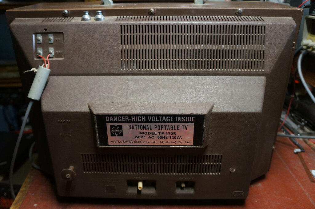
Back of set. Note the unused UHF aerial terminals. To the left of
the label is where there would be a Local-Distance switch in the original
model. At the bottom to the left of the frame hold control is the blanked
off mains input.