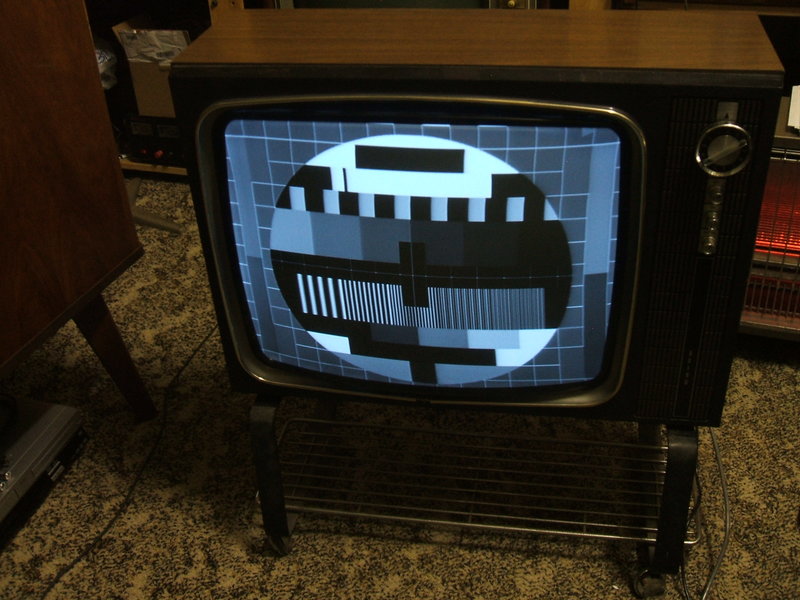
Purists will note the line linearity is not perfect. This photo was taken before final adjustment.
Purists will note the line linearity is not perfect. This photo
was taken before final adjustment.
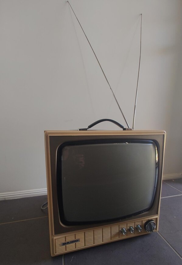
This set was acquired from a fellow TV collector who was needing to offload part of his collection. When he said "series heater" I knew I had to have it. I knew also from the description that it was one of the Thorn R series chassis, but just assumed it would be an R2. What was even better was that when I went to pick it up, I discovered it was the live chassis R2M. I could see this set becoming one of my favourites, especially as the cosmetic condition was excellent. Like my other R2M chassis (a 17" portable Baird 808), this one was also a Baird that had belonged to Radio Rentals.
Introduction to the Thorn R series
chassis.
In 1969, Thorn in the UK announced their
1500 chassis. It's a hybrid design with everything except the tuner and
controls on one PCB which forms the chassis, and is mounted on a swing
out frame. It was also of the generation of the first 625 line only designs.
Of course, being British, it's live chassis with the valve heaters in series.
As articles in Practical Television note, it's a very reliable and easy
to service chassis, which apparently remained in production until 1979.
With British viewers required to have a licence, and that the cost of a
monochrome licence is somewhat cheaper than a colour one, this meant that
large screen monochrome sets were in production for a lot longer in the
UK than elsewhere. The set was rebadged under different BRC brands and
was a popular rental set.
The BRC 1500 chassis, as produced in the UK. See "Television" for
August 1972.
An Australian version of the chassis appeared
in 1970. However, the PCB is locally manufactured and was redesigned slightly
to accommodate the differences in the Australian design. Nevertheless,
the notes in Practical Television are still pertinent. Thorn in Australia
labelled it the "R" series, and AWA called it the "58" series.
The main differences between the 1500
and Australian R and 58 series are:
Live chassis R2M.
The R2M variant is, like the R2, a series
heater version, but has no power transformer. The B+ comes from a half
wave rectifier, and the heaters are fed via a diode dropper in addition
to a 180R resistor. To make the design more acceptable in Australia, the
diode heater dropper is connected so the heaters are negative with respect
to the chassis. Along with the positive current drawn by the B+ rectifier,
this means that the DC component that would otherwise appear on the mains
is largely cancelled out.
Half wave rectification is frowned upon
in Australia because of the corrosion problems it can cause due to our
MEN earthing system. As Australian consumers have their mains neutral connected
to earth at the switchboard, it means that some current does flow through
the earth. If this should contain DC, it can cause corrosion of water pipes
to which the earth is connected. Also, a DC component is seen as reducing
efficiency of stepdown transformers in the system.
Aside from that, live chassis radios and
televisions are against the Australian culture of having an isolated and
always safe chassis which can be earthed. Hence, they were intensely disliked
by many servicemen. In fact, the R2M was the only live chassis Australian
made television since the late 1950's, when even Ekco changed over to a
transformer isolated design. Few live chassis sets existed in Australia.
Ekco was the most popular and well known, but there were some early portables
made by Admiral, Astor, and Pope Motorola.
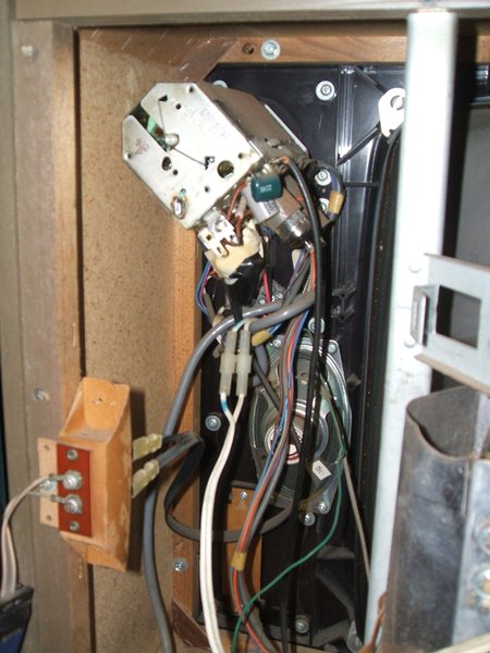
To placate the conservative serviceman,
the R2M is fitted with two neon lamps to indicate if the chassis is connected
to the live or neutral. It's quite an ingenious idea which would have minimal
increase to the cost. The mains earth is connected only to this warning
circuit, and in the case of 17" portables, to the earphone socket as protection
should the speaker transformer insulation fail. As a rental set, only the
company technicians would be working on the sets, not servicemen at large.
Thus, the live chassis work would be fairly confined to a few. For anyone
with a phobia about live chassis equipment, the obvious solution is to
use an isolating transformer.
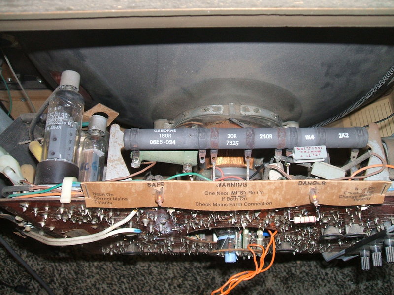
The two warning neons can be seen here. They are connected from
live to earth and neutral to earth to indicate if the chassis is live or
safe to touch. Note the 20R section of the dropper resistor.
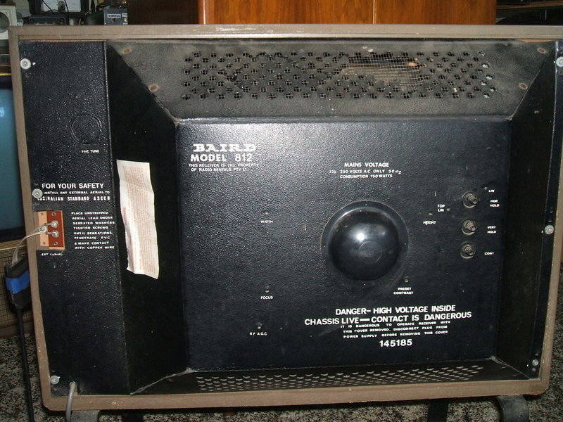
Sets using the R2M chassis were apparently used only by the rental companies, Radio Rentals (Baird) and Canberra Television (Canberra Atlas). Presumably, the live chassis was done as a cost cutting feature - plausible given the no frills cabinet designs. The cabinets and knobs are based on their English counterparts.
The Circuit.
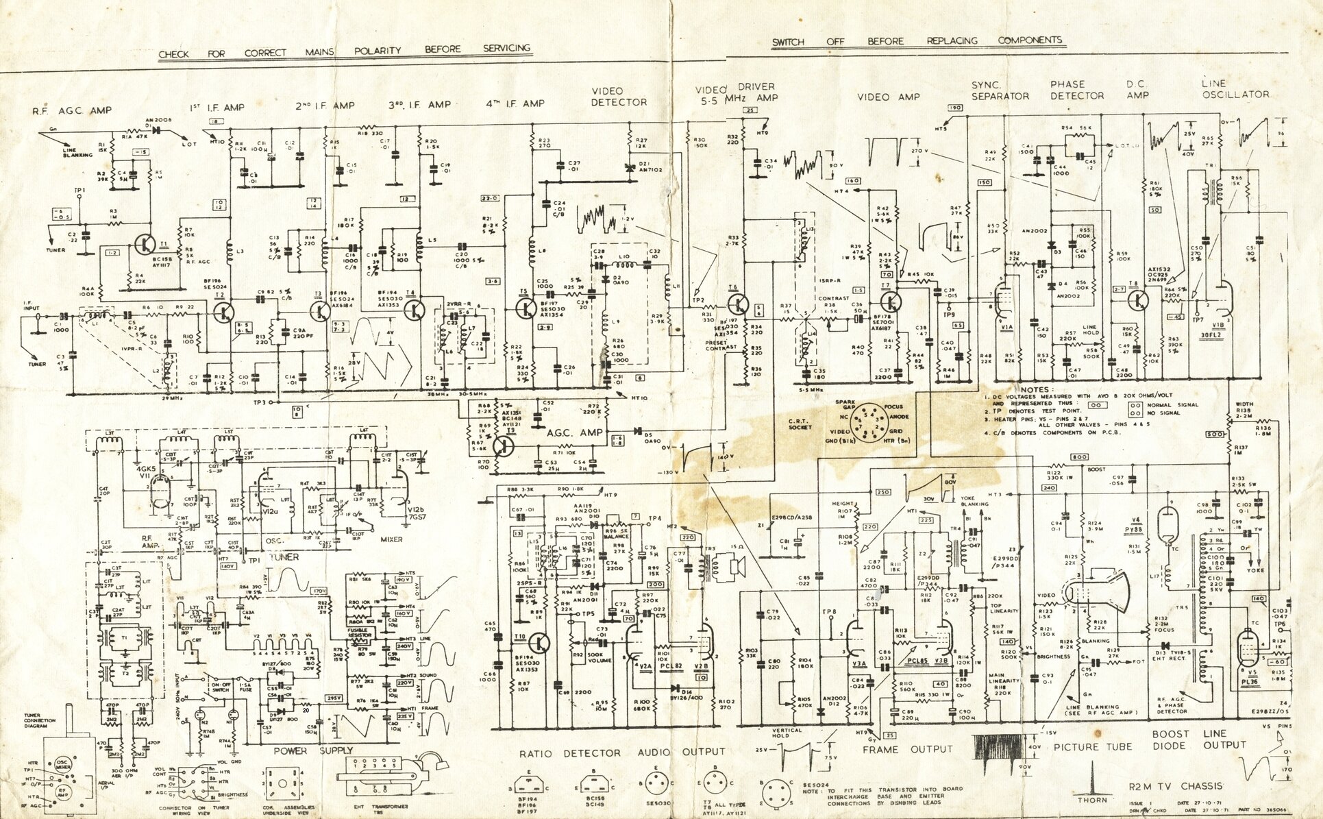
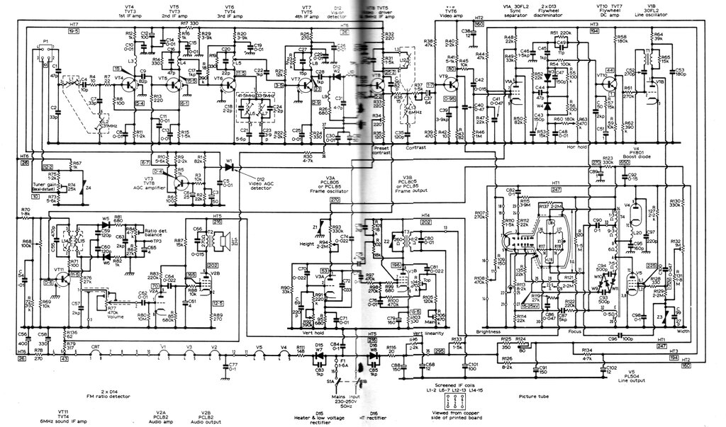
The corrected Thorn R2M circuit. Right click and view externally for full size.
Front end.
The tuner is a Matsushita VHF turret tuner
ENR5758, with series heater valves, 4GK5 and 7GS7. The 4GK5 is a neutralised
RF amplifier, and the 7GS7 is for the mixer and oscillator. 6GS7 and its
series heater versions 5GS7 (450mA) and 7GS7 (300mA) appear to be a type
unique to Matsushita, for I've only seen it in their tuners. It's pin compatible
with 6CG8, but as I found doing an experiment, not electrically identical
- some tuner realignment would be needed to get it to work.
Aerial isolation has two stages which
is quite unusual. There is an isolating panel at the tuner using 470pF
isolating condensers, and 2.2M discharge resistors, but the same thing
is also placed at the aerial terminals at the back of the set. My guess
is that it reduces the shock hazard that results when people bypass the
aerial terminals or sockets on live chassis sets. If someone connects the
aerial directly to the 300R ribbon emerging from the tuner, it will still
be isolated.
The tuner and (tiny) speaker are visible here. Inside the
cardboard enclosure for the aerial terminals is the second isolating circuit.
From the tuner, the signal is processed
by fully solid state circuitry up to the CRT cathode. Australian made Fairchild
or Philips transistors were used. The IF amplifier consists of transistors
T2, T3, T4, T5. D2 provides detection, and the video signal now passes
through T6 which is an emitter follower, the output of this being low impedance.
This reduces problems with stray capacitance and provides low impedance
drive required by the video output amplifier, T7. A simple contrast control
is wired rheostat style to the input of T7. From T7's collector, the signal
is now strong enough to drive the CRT cathode. The CRT is a Philips Miniwatt
A61-120W/R.
Note that the video stage is entirely
AC coupled. DC component is lost at C36 and C38. High frequency boost to
is obtained by C37 in T7's emitter circuit. No peaking chokes are used
(and it seems not required) in the video amplifier circuit. A series resonant
sound trap is present at the input to T7 to prevent 5.5Mc/s patterning
in the picture.
The AGC is peak level. The peak voltage
of the detected video is rectified by D5, which charges C54. As the peak
level is proportional to the sync pulse level, this voltage does not vary
with video content, only the signal strength. T9 amplifies the filtered
DC obtained thus, and uses it to control the base current of the first
and second IF amplifiers, T2 and T3. Although the AGC is fed into T3, T2
takes its bias current from the emitter of T3.
The tuner, using valves, requires negative
AGC. A negative supply is obtained by rectifying pin one of the line output
transformer. C4 filters this to a steady -15V. This is fed into the AGC
terminal of the tuner via R3 and R5. However, T1, at the junction of these
two resistors is used to shunt away some of this voltage, depending on
the current drawn by T2, the first IF amplifier - this being of course
AGC controlled. A quick glance at the circuit may assume gated AGC because
of the connection to the line output transformer, but this is not
the case - it's merely a convenient way to obtain negative DC.
T6 also functions as a grounded emitter 5.5Mc/s amplifier, thus providing the first part of the sound IF amplification. This proceeds to T10 where the further amplified FM signal is fed into the ratio detector transformer L15/L16. A pair of germanium diodes provide detection. For complete AM rejection, a balance control is provided to take up any mismatch between the diodes.
Picture Tube.
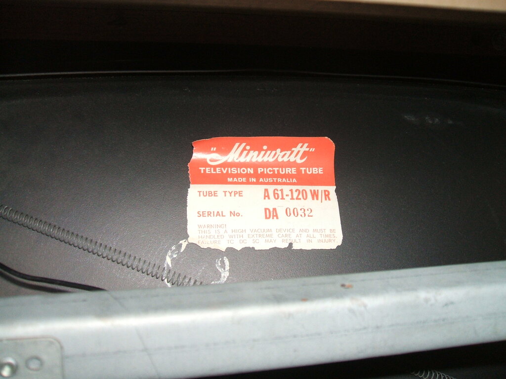
24" Picture tube was made by Philips. The size is not common in
Australia, with most large tubes being 23" or 25".
Audio.
Here a 16A8/PCL82 is used in the conventional
way. This valve is the 300mA series heater version of the 6BM8/ECL82, which
appears in the R1 and 58 series chassis. One gets the impression that anything
to do with audio was an afterthought in the design. Apart from the speaker
being the same as used in a 12" Thorn portable, there is no frequency response
correction, except for a crude .01uF across the output transformer, and
an unbypassed 270R cathode resistor for some negative feedback. The diode
(D14) shown connected to the pentode cathode is not related to the audio,
but is part of the power supply which is discussed later.
Sync separator and line oscillator.
The valve used here, 30FL2 and its parallel
heater version, 6FL2 are unique to Mazda, sometimes branded as Ediswan.
In Australia, the R series was the only set to ever use these valves. The
numbering is misleading in that although it looks like an RMA number, the
30FL2 certainly does not have a 30V heater! It's actually 10.4V. The pentode
section is, despite the appearance on the circuit, a tetrode. It's specifically
intended for sync separation circuits. The circuit here is quite standard,
with the video output transistor, T7 providing drive to the grid via the
isolating network R45 and C39. Frame sync pulses are taken from a tapping
on the plate load so as not to filter out the line sync which is taken
directly from the plate. The sync separator operates with low plate and
screen voltages, as is usual to clip the sync from the video.
As is standard, an AFC circuit is provided
for the line oscillator. A phase detector consisting of D3 and D4 produces
an error voltage if the line oscillator is not in phase with the sync pulses.
Line pulses come in via C44, and sync pulses via C43. The resultant DC
is filtered by C48. R60 and C49 provide critical damping so that sudden
changes do not cause hunting. T8 amplifies the correction voltage, which
then controls the grid voltage of the triode. The triode is a simple transformer
coupled blocking oscillator. Some control over its frequency can be obtained
by altering the grid voltage. To set the line frequency into the capture
range, the line hold pot provides an offset voltage to the AFC circuit.
Drive to the line output stage comes from
the triode plate.
Line deflection.
The line output stage is designed around
a Philips line output transformer and is stabilised with a VDR. The line
output valve is a 25E5/PL36, and in the parallel heater chassis, it is
a 6CM5/EL36. The 6CM5 was the "standard" line output valve in Australia.
By the mid 1960's every local manufacturer was using it. Even AWA let go
of their beloved 6DQ6.
It's an efficient valve with excellent
reliability.
It is not entirely clear because of the
circuit copy, but the width stabilising VDR, Z4, rectifies one of the line
output transformer tappings. How can a VDR rectify you might ask? The secret
is that the waveform fed into is asymmetrical. As Z4 receives a pulse,
it reduces resistance and C101 charges up. One the next half cycle the
pulse is much less, so the energy in C101 now appears across Z4 in the
form of a negative voltage. This is superimposed on the output valve grid.
As line output activity increases, the more negative voltage appears on
the grid, and so the PL36 is throttled back. On its own, the negative
voltage produced would be too much, but the width control provides an adjustable
positive offset to this, so the line output stage operating conditions
can be set.
The damper diode is a 30AE3/PY88. For
parallel heater sets, it's 6AL3/EY88. C97 is the boost capacitor. The yoke
is also a Philips, and to adjust linearity a shorting sleeve is fitted
to the neck of the CRT. Thus, the inductance of the yoke can be increased
or decreased depending on how far in or out the sleeve is. This type of
linearity control is apparently a Thorn invention. Some sets use a Plessey
yoke.
EHT is obtained by a selenium stick rectifier,
TV18S.
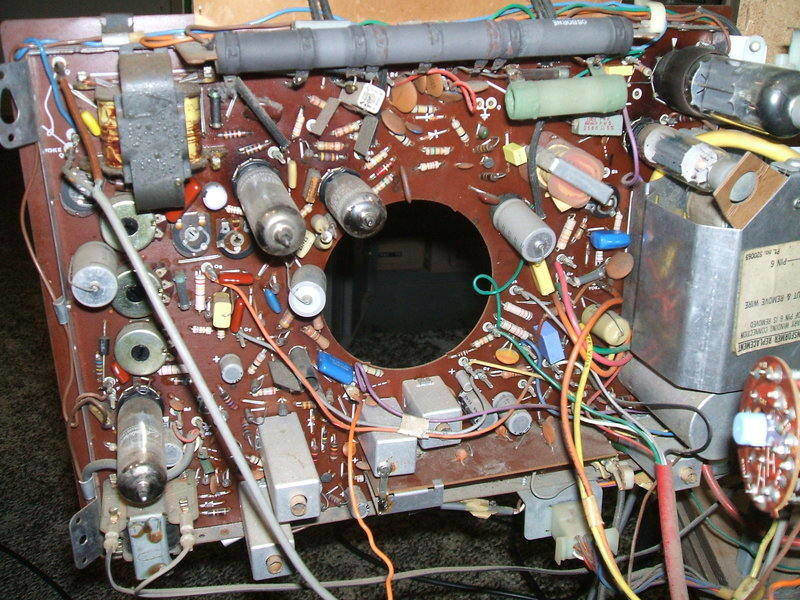
The chassis is one of the best for service access. Undo one screw,
loosen one other, and it just swings out. Everything is easily accessible.
Valves from left to right are PCL82, PCL85, 30FL2, PY88 and PL36.
Frame deflection.
This uses a 18GV8/PCL85, or 6GV8/ECL85
in a standard multivibrator circuit. The triode forms the oscillator
in the usual way, with the plate resistor R108 charging C86. The amplitude
of the charging voltage, and thus the height is set by adjusting the supply
voltage. This is also stabilised, by a VDR, Z1, to reduce the effect of
changing mains voltage on picture height. The charging waveform is fed
into the pentode output stage. Waveshaping components are used to obtain
correct linearity by modifying the output stage waveform, by C92 and the
main linearity control. Further adjustment is provided by a feedback circuit
based around C88 and the top linearity control. C82 provides the cross
coupling to make the circuit oscillate. C91 across the yoke terminals bypasses
the line energy coupled in between the line and frame windings on the yoke.,
which if it gets into the frame oscillator, can upset the interlace. The
pentode cathode current is filtered and provides the 25V supply for the
front end of the set.
Power Supply.
Mains is fed in via a double pole switch
to ensure the chassis is not live when the set is switched off. Neons N1
and N2 indicate chassis polarity by using the mains earth as a reference.
If N2 lights it means the chassis is live, and the polarity should be reversed
before commencing work. Both neons light up if there's no earth because
they're then in series with each other. This is the case when using the
set with an isolating transformer, but in this case they do not indicate
danger.
A single 1.5A fuse protects the whole
set. D9 rectifies the 240V mains which charges the main B+ filter condenser
C58, 150uF. A .01uF ceramic condenser protects the rectifier diode against
mains spikes. There is a 20R surge limiter in series with D9 to limit peak
charging current of C58 when the set is first switched on. A mistake exists
on the original circuit diagram in that this resistor is not shown. Physically,
it's part of the big black dropper resistor across the top of the chassis.
No resistor is required when a transformer is used because the winding
resistance functions thus. In the transformer powered sets a bridge rectifier
is used.
Resistors and high value condensers provide
all the filtering. There is no choke. Most of the filter resistors are
part of the long black dropper resistor along the top of the PCB.
The valve heaters are all 300mA and connected
in series. To reduce the heater dropper resistor power, a diode is used
to cut off every half cycle of the mains supply. Thus, the heater string
is fed half the power that would otherwise be fed into it. Effectively,
with
the diode in circuit, the heater supply is 170V rms instead of 240V. This
means a smaller dropper resistor.
The technique is discussed in detail here.
| Valve | Heater Voltage |
| CRT | 6.3 |
| 4GK5 | 4 |
| 7GS7 | 7.6 |
| PCL82 | 16 |
| PCL85 | 18 |
| 30FL2 | 10.4 |
| PL36 | 25 |
| PY88 | 30 |
| Total = 117.3 |
We can see the 180R dropper resistor is
correct from a simple calculation. As previously stated, the diode dropper
converts the 240VAC supply to 170V rms. The voltage to be dropped across
the resistor is 170 - 117.3 = 52.7V.
R = V/I = 52.7/0.3 = 175.7 ohms, which
is close enough to the nearest preferred value of 180R. Power dissipated
is I^2 x R = 0.3^2 x 180 = 16.2W.
Just as an illustration of how the diode dropper saves power (and heat), let's calculate the dropper if the circuit didn't include the diode. R would be 240-117.3/0.3 = 409R. Its power dissipation would be 0.3^2 x 409 = 36.8W.
In the original circuit diagram, the heater
dropper diode D8 is drawn the wrong way round. This is the convention in
the UK and Europe where they don't care about huge chunks of power drawn
on every half cycle, and it would appear whoever draughted the Australian
circuit overlooked this when redrawing the 1500 circuit. I have corrected
this in the circuit shown here.
Having the heater dropper feeding negative
voltage into the heater string offsets the current drawn by the B+ rectifier,
and thus reduces the DC superimposed on the mains.
In the original 1500 chassis, the low
voltage for the front end was obtained from a voltage divider at the earthy
end of the heater string. But, as the Australian R series has the heater
string negative with respect to earth, this technique cannot be used. Hence,
the modification to use the frame output valve cathode as a supply source,
as mentioned previously.
A potential problem of the heater diode
dropper is that if the diode shorts, as diodes tend to do when they fail,
full power is applied and the valves will be damaged. The user would be
unaware of this as the set will continue to function. Only by looking in
the back and noticing the increased valve brightness would the fault be
detected.
However, a warning circuit is provided
for in the R2M. Referring back to D14 in the audio circuit, it will be
seen that one end of the diode is connected to the unbypassed pentode cathode.
The other end is connected to one of the heater pins of the PCL82. Note
the polarity. Because the heater string is negative pulsating DC, the diode
does not conduct. It does nothing. Now, imagine the heater dropper diode
shorts. Then, the heater string will be running on AC. D14 will now conduct
each time heater pin 4 goes positive - thus feeding pulsating DC into the
output valve cathode. The result is a loud buzz from the speaker which
cannot be reduced even with the volume control. Hence, the viewing conditions
are made unpleasant enough for the viewer to turn off the set.
It is interesting to note that Pye incorporated
an audible warning system in some of their chassis to indicate if the heater
fuse had blown. Here the earth return of the speaker was via the fuse,
so if the fuse was open, 6.3V at 50c/s would be fed into the speaker.
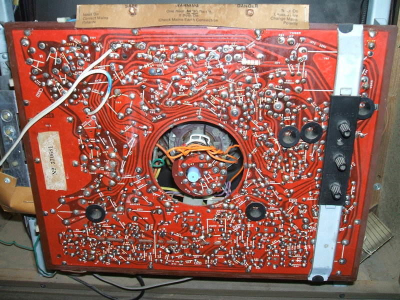
Back of the PCB. The white twin flex is the 240V mains input.
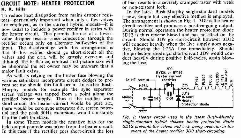
While there is no doubt that the audible warning system works, a potential problem is if the audio stage or speaker is also faulty. Note that if the heater of the PCL82, tuner valves, or CRT should go open, or if any of these valves are removed with the set on, the PCL82 pentode cathode resistor will burn out with the full heater current applied across it. A far better method is to have a diode connected from the heater supply to earth so that it is normally reverse biassed. If the heater dropper diode shorts, then the protection diode will conduct on the first positive half cycle and blow the fuse. This has been described here https://www.cool386.com/dropper/rsz_1pt_aug71.jpg
Restoration.
The R series chassis was one of the most
reliable Australian sets, and quite a few were being used into the 1980's.
In later years, they succumbed to the problem of leaky paper condensers.
By the 1990's these were starting to fail. Paper condensers in a 1970's
TV set? Yes, indeed. They were the last attempt at making a leakproof design.
The type concerned is the PCB mounted AEE Miniprint. These were encapsulated
in clear resin. As far as paper condensers go, they were actually very
reliable at the time, but mounted next to hot valves the resin would eventually
crack, leaving the insides exposed to moisture.
So, first job was to replace these. I
did actually power up the set beforehand just to see what it would do,
but the .056uF boost condenser soon failed, and with C94 leaky, the CRT
did not light up anyway.
I was keen to see the CRT light up after
seeing a note on the service card saying something about boosting the CRT.
I had visions of a serviceman unnecessarily stripping the tube cathode
because he couldn't be bothered changing a high resistor or leaky condenser
in the CRT grid circuit. Given the tube is a Philips Miniwatt, I knew the
chances of it failing were very unlikely. Nevertheless, the previous owner
assured me the CRT was quite OK.
All the likely high value resistors were
changed, but only a few were actually found to be out of tolerance.
I now had screen illumination thus putting
my mind at ease about the CRT. There was however, no frame deflection,
and the width was rather lacking. The frame circuit was missing its B+
because the 1.4K filter resistor (R76) was open. This was strange not being
a preferred value, and I put a 1.5K 5W across the terminals just to get
it going. Subsequently, I paralleled a 22K 1W across it because there was
a small but noticeable difference with the lower value. In reality it wouldn't
have mattered and I'm sure most TV servicemen would just use 1.5K. Because
this resistor is part of the big black dropper, I soldered it to the leads
from that, cutting one off the dropper just in case the open circuit section
came good.
As with every other example of the R2M
chassis I've seen, the 180R heater dropper had gone open circuit in the
past and had been bridged with a separate 20W resistor.
For those with R1 and R2 sets, as well
as an R2M, one could swap the dropper over if one wanted the original type
because the 180R section is not used in these sets, so it is in pristine
condition. The burnt out dropper can then go into the transformer powered
set.
Having now got a raster, a strange distortion
was evident at the bottom of the picture. I had never seen it before and
although not keystone as one gets with shorted yoke turns, it did look
yoke related. I thought I should get a picture first to try and understand
what it was. The width was still lacking despite trying new valves, etc.
Feeding an RF signal into the aerial terminals
did not produce what I expected. I've never had a front end problem with
the R series and this was very strange. The "picture" was very weak and
looked off tune and altering the fine tuning did not correct this. I thought
maybe an AGC fault was cutting off the RF or IF stages, but when I checked
there was no AGC being fed into the tuner.
So, out with the 100Mc/s CRO and trace
through the IF stage. The video detector transformer was providing 5V p-p
into the detector diode, but only millivolts were coming out. A quick ohms
test confirmed the diode was open. Replacing it brought up full gain and
a strong picture.
Thinking about the raster distortion,
I took the yoke from my spare R2 chassis to try it out. As I was sliding
back the yoke on the R2M to remove it, all became clear. The linearity
sleeve was so far down the neck that it had been splayed out against the
back of the CRT. Soon as I removed it, up came a distortionless raster
of more then enough width.
With a Philips PM5544 test pattern fed
in, the sleeve was then adjusted correctly. It protrudes from the back
of the yoke by about 12mm.
The set was now working very well, with
a good sharp picture. Running it for several hours showed up a new fault.
The height was intermittently dropping. A likely problem was something
in the height circuit and my suspicions focussed on the 1uF electrolytic,
C81. Knowing the unreliability of such components, it was replaced and
the fault has not returned.
Back of set showing preset controls.
17" Baird 811 or 808.
The more common version of the R2M was the Baird 808 or 811, which is a 17" portable. The only difference between the 808 and 811 appears to be the construction of the back cover. The 808 was prone to the top of the back cover disintegrating since the dropper resistor is so close. The 811 has this part made from plastic, which is a bit more durable than the fibreboard used for the 808. There is also a transformer isolated version of this set with the R1 or R2 chassis, usually branded Thorn, which was also available in a woodgrain finish.
