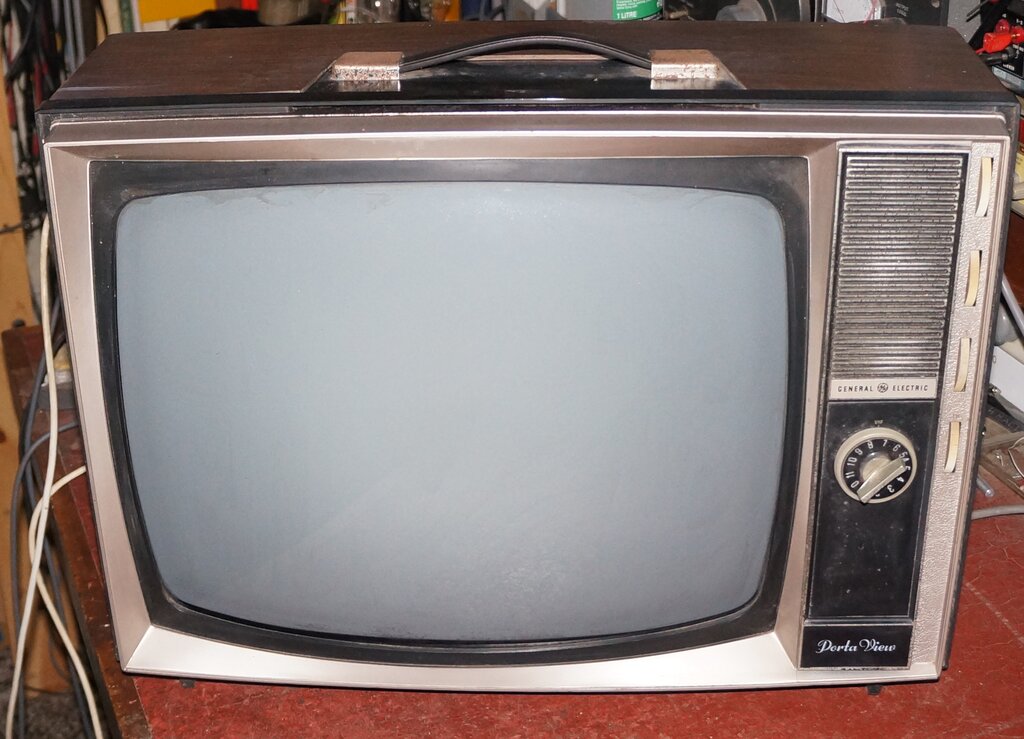
This set has been in my collection for about 18 years, having come from a council clean up campaign, and it's only recently that I decided to have a good look at it. Like all the other GE valve portable sets sold in Australia, it uses Compactron valves.
General Electric portable TV's in
Australia.
General Electric's portable sets are interesting
because they are what brought Compactrons to Australia. The sets themselves
are of U.S. design, which was modified, and then assembled in Australia
by James N Kirby Appliances. Not surprisingly, the sets are series heater
since the U.S. versions do not use a power transformer.
Initially, GE's first portable in Australia
was an 11" set, released in 1964 and designated TF1. This was a U.S. model
SY, which had been adapted for Australian use by supplying an outboard
120V transformer. Additionally, the tuner was a locally manufactured Steane
or MSP type, and of course the video and sound IF were altered for Australian
conditions. Since the 625 line system used in Australia was based on the
U.S. 525 line system used in the U.S., the alterations are simple. Negative
modulation and FM sound is common to both systems. The line frequency is
very close, being 15,750Kc/s for 525 lines and 15,625Kc/s for 625 lines.
Thus, no modification is required for the line deflection circuit. Similarly,
the 60 field frame rate (U.S.) is close enough to the 50 fields used with
the 625 line system that the circuits are the same; the normal frame hold
control having enough adjustment to work on the lower frequency. The main
difference is the 4.5Mc/s sound IF used with 525 lines, whereas it's 5.5Mc/s
with the version of 625 lines used in Australia (system B). Less important
is the different video IF standards.
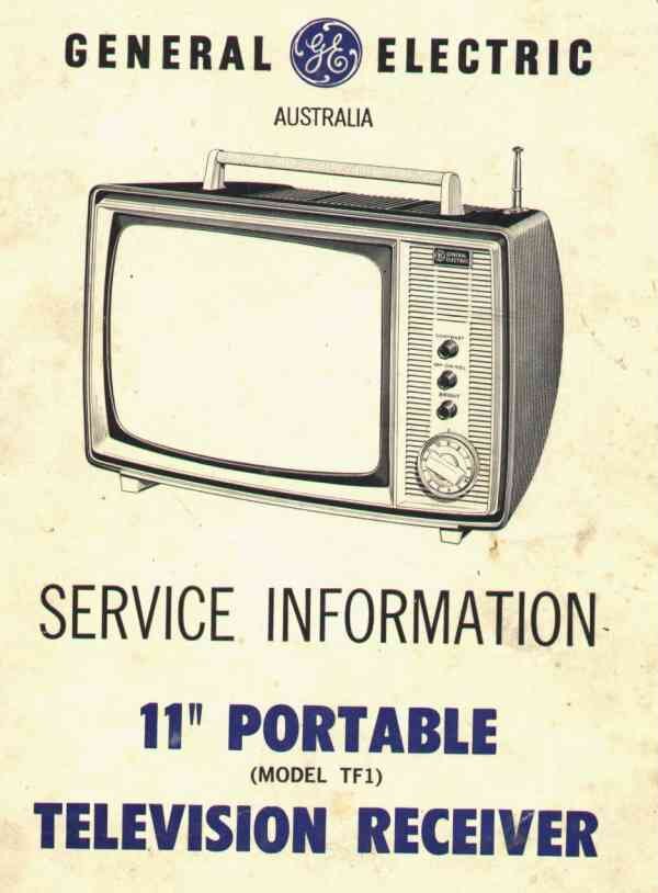
GE's first portable in Australia was this 11" set using an outboard
240 to 120V transformer. I'm looking to add one to my collection.
It was a popular model, and its release
forced AWA to develop their 11" P1 portable. Externally, the resemblance
was obvious, but internally the AWA set was completely different, using
an entirely local design.
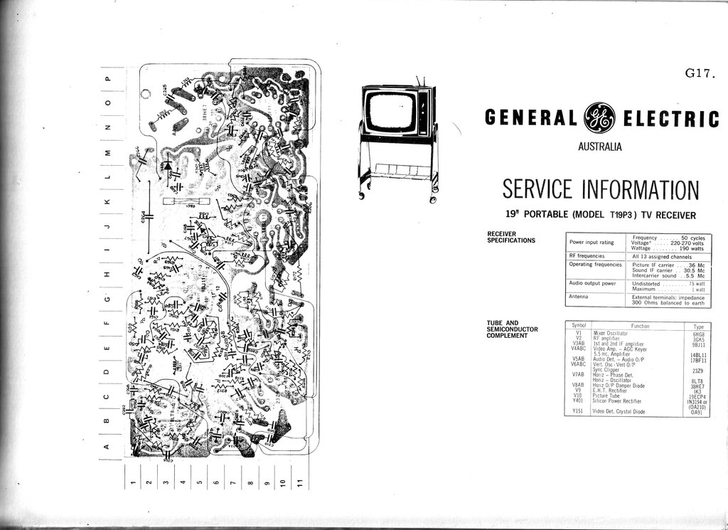
Later, GE released 12", 16" and 19" portable
sets, again based on their U.S. counterparts. By this time, the power transformers
were mounted inside the sets.
Where possible, locally produced components
were used, but otherwise they were imported.
It is interesting to look at the Australian
modifications to these sets. In some cases they are quite crude. The construction
of the sets (and their U.S. counterparts) were clearly made to a price.
Technicians did not like them, since the service access can be very difficult,
and of course, Australian technicians have difficulty with anything but
the usual 6.3V parallel heater valves, which the local industry was based
on. Funnily enough, it's the sets everyone else hates that I like the most!
My first GE Compactron set (16") was bought
for $2 in a second hand shop in 1981. It was inoperative, in that there
was sound but no picture, and back then I really had no idea what its fault
was. I erroneously assumed that since all the valves were lit that it wasn't
a valve fault.
I took it to the local TV repair shop
and the technician didn't want to touch it. He said he'd have to import
any Compactrons from America which would be expensive, etc. I realised
later this was a cop-out because Compactrons were actually standard with
local valve suppliers. Even Tandy had been selling them! Sadly, the set
got pulled apart, and in hindsight, I'm almost 100% sure that the fault
was the damper diode in the 33GY7 was open circuit. On a positive note,
I have since accumulated quite a number of Compactron portables, including
some of the 16" models I had back in 1981. I am looking for one of the
11" GE TF1 models, so if you know of one, please get in touch.
Compactron Valves.
These were designed by GE in the early
1960's as a way of reducing the valve count in a set. Each Compactron contained
two or three valves in the one envelope, and were fitted with a 12 pin
base. Both parallel and series heater versions were produced. In some instances,
the valve sections were based on existing single types. Aside from GE,
National used a compactron (38HE7) in their locally assembled portables
(Japanese models similarly modified for Australian conditions). Otherwise,
Compactrons were ignored by the typically conservative local manufacturers.
They were of course much more popular in the U.S, and several manufacturers
used them. With a printed circuit board, a set using Compactrons could
be made very compact, as the name suggests.
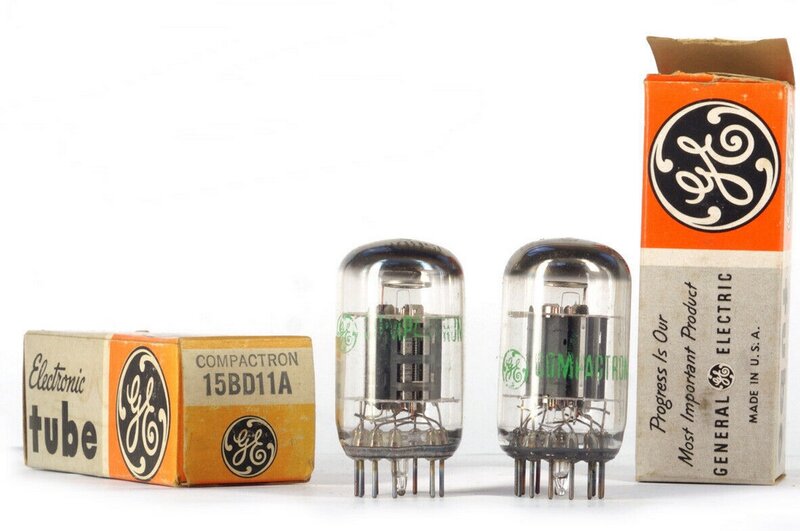
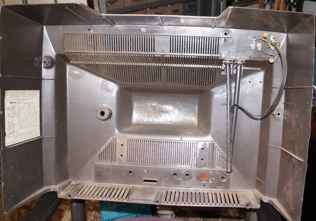
The 15BD11 contains two triodes and one pentode.
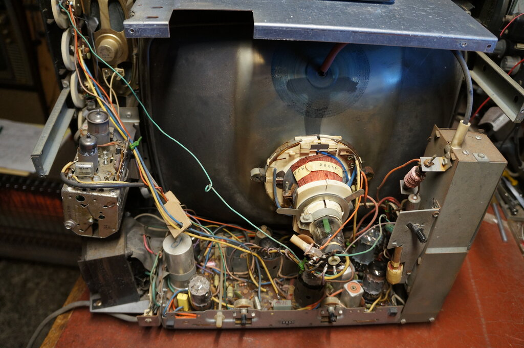
The power transformer at the bottom left is a local addition.
Several aspects of the construction stood
out. The first is the MSP (AWA) deflection yoke. The 12" and 16" models
use a narrow neck picture tube, and since no local manufacturers were using
these tubes, locally made yokes for them did not exist, hence they were
imported.
The tuner is a Matsushita (National/Panasonic)
ENR-5759. The ENR-5758 was being used in various Thorn sets produced locally.
There appear to be no obvious differences between the two types. The tuner
bracket has not been altered sufficiently, because with this tuner, the
channel numbers on the knob do not line up perfectly with the indicator.
Since the U.S. version of this set is
120V and live chassis, a power transformer (made by Ferguson), and the
base plate it is mounted on, have been added. It feeds an isolated 120V
into the set. The transformer installation looks quite good in this set.
With the 12" and 16" models, it has been shoe-horned in, and the extra
weight was sometimes too much for the plastic cabinet. This set weighs
about 13kg; no doubt a good deal heavier than its U.S. counterpart with
no transformer.
Like the other models, one can see where
the 120V input socket would be for the original U.S. version.
Of course, the Australian model does not
include a UHF tuner, but it's obvious where it would go, with the front
panel chassis having a cut-out for it. Many of the capacitors are of local
Philips production, and are polyester or polycarbonate. It is fortunate
that GE avoided paper capacitors, and this compensates for the not so good
service access when restoring one of these sets. Resistors are partly IRC,
although there appear to be some U.S. made types, and some others of indeterminate
origin. As such, restoration is mainly resistor replacement, since the
IRC product has not survived well over time.
From the date stamps on various components,
this set was made in 1973. It was of the last generation of locally assembled
valve monochrome set. GE's colour sets which appeared soon after were a
rebadged Hitachi chassis.
Getting it Going.
Not having to replace any paper capacitors
means there's a pretty good chance of something useful happening when one
of these sets is powered up. In this instance, nothing happened. The first
obvious problem was the 38HE7 line output and damper valve was broken.
How this happened is not known. A drop of water down a ventilation slot
onto the hot valve perhaps?
Replacing this restored line deflection,
except this showed up no frame deflection. Again, with the general reliability
of the passive components of these sets I considered the 23Z9 frame oscillator/output
valve might be faulty. Because of the non logical and cramped layout, it's
difficult to trace out the circuit for measurements, so it's easier to
try the valves first. Indeed, another 23Z9 restored frame deflection.
Next, the speaker was completely dead.
The 17BF11 quadrature detector/output valve looked like the getter had
all been used up, so it too was replaced. Now we had some scratching and
faint hum as the volume control was rotated. This left the problem of no
video.
Injecting a signal into the IF at the
output of the tuner didn't show anything, so that at least eliminated the
tuner. Seeing the 9BJ11 video IF amplifier heater looked dull (like it
was almost devoid of vacuum), I replaced it, and we finally had a picture
and sound.
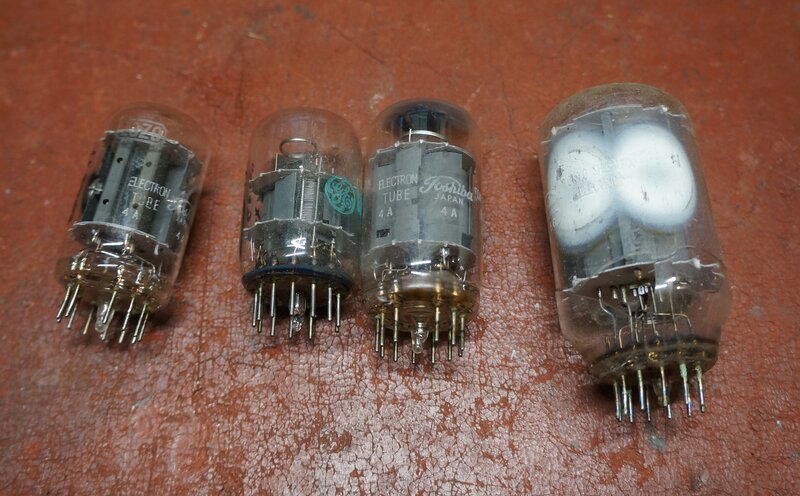
Faulty Compactrons.
In my entire TV servicing career of about 35 years, I have never seen so many faulty valves in the one set. Most sets I have worked on haven't needed any valves replaced, but here were four faulty ones in one go. This is the first time since 1981 that I've encountered a faulty Compactron. The only unusual thing I noted was corrosion on the pins of several of the valves. If this somehow made its way up into the glass envelope, then it would be no surprise for vacuum to be lost. The general appearance of the set when I found it suggested it may have been 'stored' out of doors for a time.
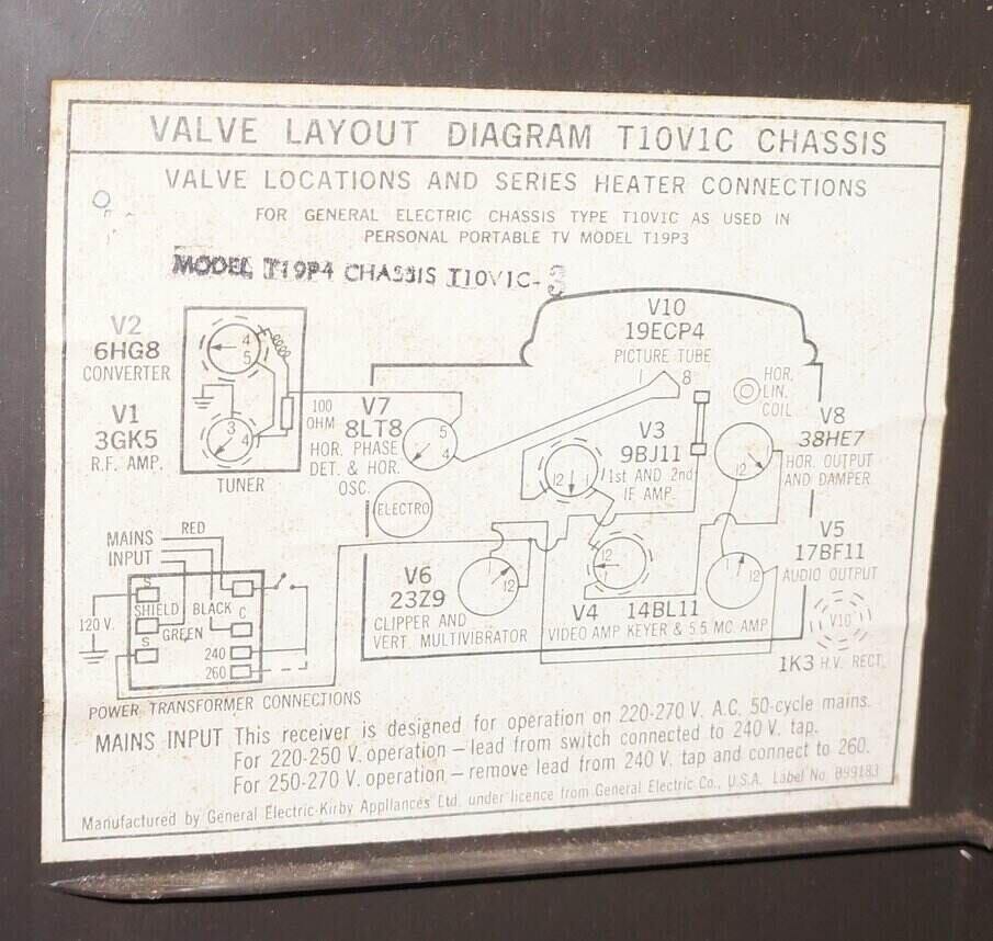
Valve layout diagram. The tuner valve types and heater shunt resistor
are different to what is in this particular set.
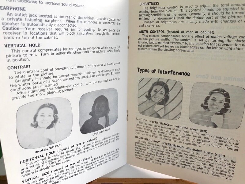
With a touch up of the various preset controls, a good picture was obtained.
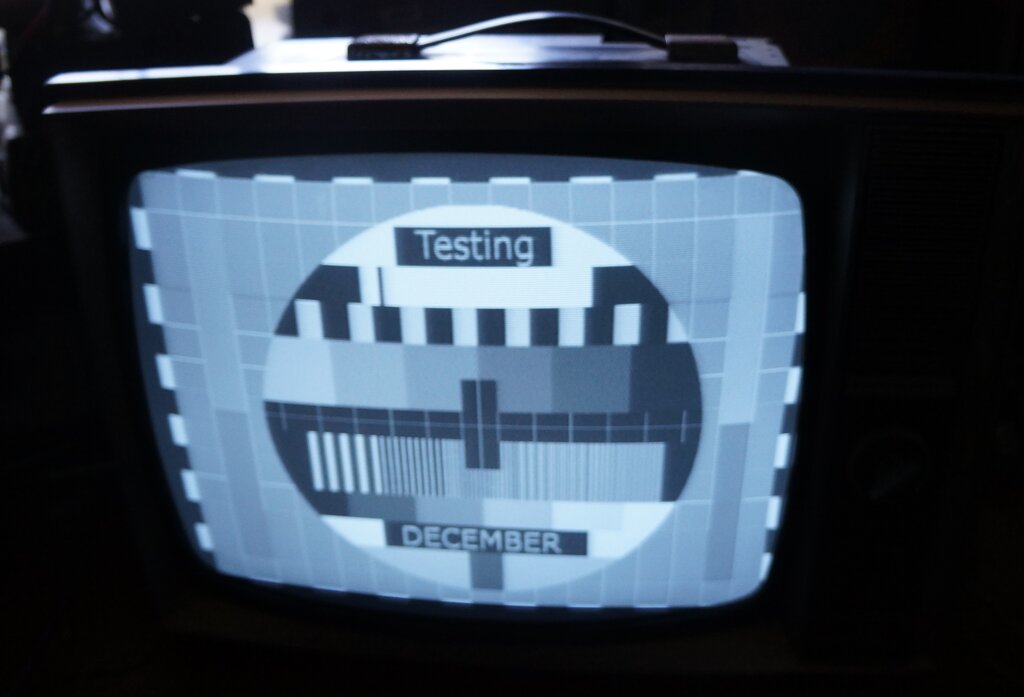
Cost cutting is evident in that while the picture is sharp, the video bandwidth is perhaps less than it could be. This is not surprising, since with only two stages of video IF amplification, the bandwidth would have to be compromised to obtain sufficient gain. The 9BJ11 does not seem to be of frame grid construction, judging by its characteristics (7500 and 9600 umhos for each section). Nevertheless, the picture is perfectly watchable by the average viewer.

The dark bar is due to the camera shutter.
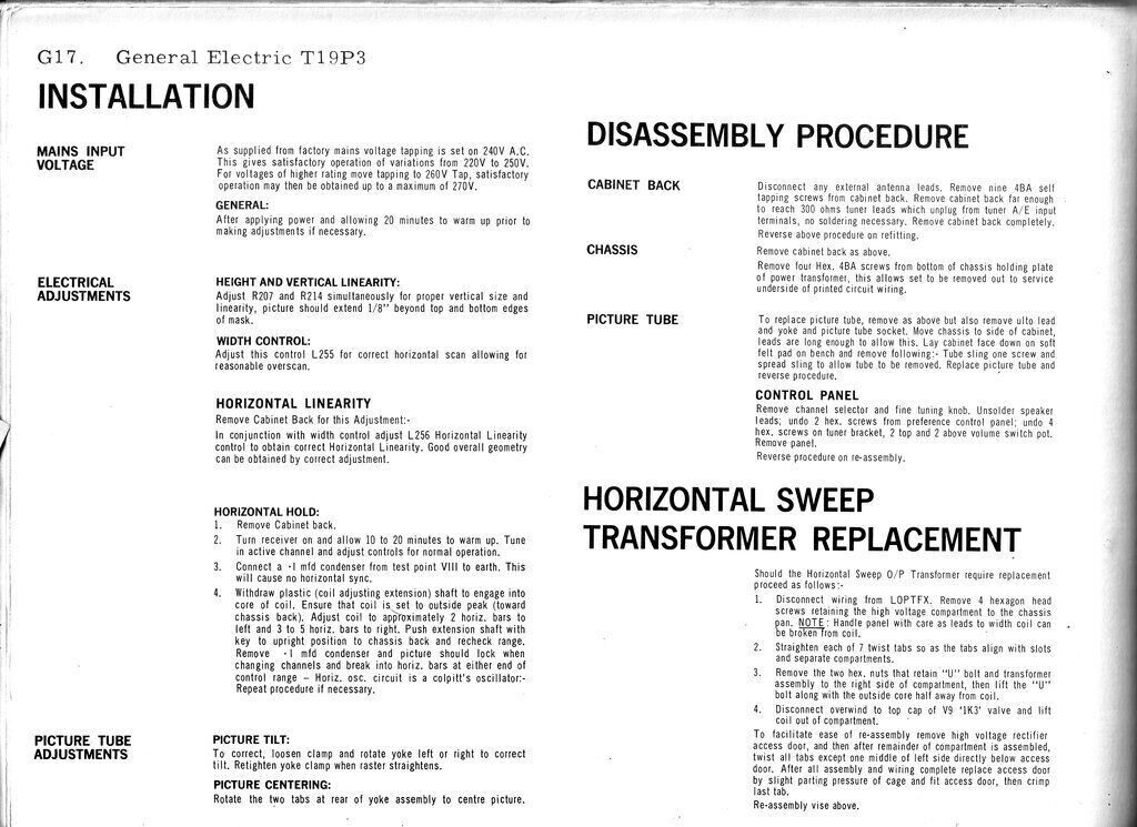
There was no problem setting the picture
geometry for a round and centered test pattern. The height and linearity
controls, while interactive, are not difficult to adjust. The user adjustable
width control is unusual, and seldom seen. Unlike most 110 degree sets
of local design, the GE does not have a stabilised line output stage, so
it's conceivable the adjustment can be used to compensate for change in
mains voltage.
I discovered that the 1K3 EHT rectifier
had been replaced by a selenium stick rectifier. Whether this had been
done during manufacture or during a later repair is not clear. Seeing as
the modification had been done acceptably, it was left in situ.
Inside the back. Note the power cord entry at the bottom right.
The original 120V input has been blanked off by the locally made decal.
Note the brown rectangular hole towards the bottom right.
Because the Australian set is connected
to the mains with a three core flex, the U.S. method of having a two pin
interlock on the cabinet back can't be used (except for the original 11"
TF1). While the location of the interlock is evident on the chassis, and
the cabinet back, it's blanked off by a locally made aluminium decal. To
get the flex into the set, for this and other models, it looks like a soldering
iron has been applied to the edge of the plastic moulding to melt a suitable
entry slot into it. Needless to say, the cord storage hooks on the cabinet
backs don't accommodate three core flex properly, since they were designed
for twin flex ('zip cord' in the U.S.). This set has no cord hooks, but
it's obvious where they would normally be.
Another peculiarity with this set is the
aerial terminals.
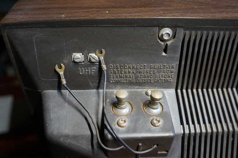
Note the terminals labelled UHF.
They're clearly labelled UHF, even though there's no UHF tuner. There is an indentation in the moulding to the left which could be where the VHF terminals would be in the U.S. version, but since I have not seen one I can't be sure. The 12" and 16" portables are even more crude, using a piece of phenolic fitted with a couple of Fahenstock clips, screwed onto the back over the hole where the terminals normally are. However, in those sets, the reason for so doing is because of the power transformer being in the way.
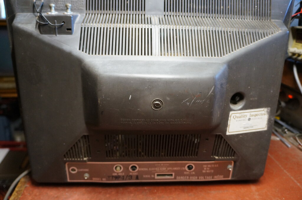
Back of cabinet. The locally applied decal has not been applied
evenly and is bowed.
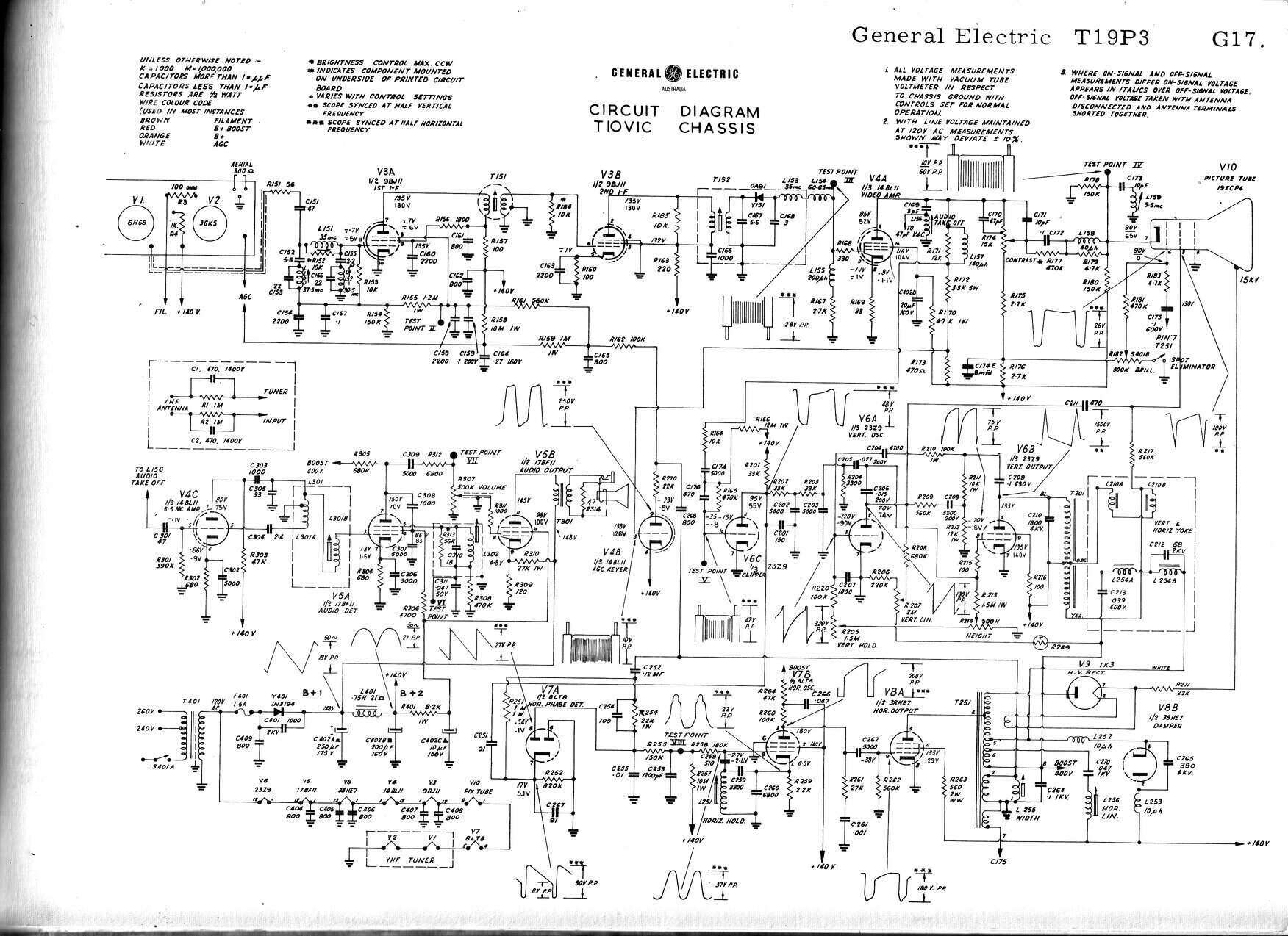
Except for the neutralised triode sound IF amplifier, the circuit
is conventional.
Front End.
A conventional VHF turret tuner is used.
Why the aerial isolation components have been included is curious, since
the set has an isolated (and earthed) chassis. Contrary to the circuit
diagram, the tuner installed is a different type, made by Matsushita. It
uses a 4GK5 RF amplifier and 7GS7 converter. These valves are designed
for a 300mA heater string, but since the GE uses a 450mA heater string,
a 75R 7W resistor is shunted across the heater supply of the tuner, to
absorb the extra 150mA.
It's an interesting question as to why
a 3GK5 and 5GS7 were not used, since these have 450mA heaters, removing
the need for the shunt resistor. Presumably the tuners were already supplied
with the 300mA valves, and it would be cheaper to install a shunt resistor,
rather than replace the valves.
The IF from the tuner proceeds to a two
stage amplifier using a 9BJ11 dual pentode. From here, the video is detected
by an 0A91 germanium diode, before proceeding to the pentode of the 14BL11,
which performs as the video amplifier.
Video Amplifier & CRT.
The video stage is entirely conventional,
with the 14BL11 pentode biassed largely by the negative going video signal
from the detector. It's a typical resistance coupled circuit, with a peaking
choke (L157) in the plate circuit, to improve the frequency response. A
high level contrast control is used, this being in the plate circuit. Effectively,
the contrast control is wired as a variable tap-off across the plate load
resistor. Since this type of control is affected by stray capacitance,
compensation is required in order not to lose high frequency response at
certain settings of the control. C170 and C171 perform some of this compensation.
Additionally, it's important to keep the wires to the contrast control
and to the CRT spaced away from the chassis and other wires.
L158 compensates for the cathode capacitance
of the CRT. The CRT is mostly AC coupled, which is typical of American
practice. R177 provides a compromise between full DC coupling, and full
AC coupling. Full DC coupling, while ideal from a theoretical point of
view, can be difficult to implement. It means the picture can be prone
to shifts in brightness, if the black level is not maintained perfectly
at the transmitting end. Also, the AGC circuit must be perfect, since any
change in front end gain will affect the DC level at the video amplifier
plate, and thus the CRT cathode. Additionally, it is usually found that
brightness and contrast controls become interactive, and difficult to adjust
correctly for a non technical viewer.
In short, AC coupling makes for cheaper
set design, and less critical adjustment.
The CRT is a 19" 110 degree 19ECP4. A
series tuned circuit trap for the 5.5Mc/s sound IF (C173 and L159)
is connected right at the CRT cathode on the CRT socket. Brightness control
is by varying the grid voltage relative to the cathode. There is a spot
suppression circuit, to prevent a dot appearing in the centre of the CRT
when the set is switched off. This is a typical circuit whereby the earthy
end of the brightness control is connected via one pole of the power switch.
When the set is switched off, the grid voltage rises towards the B+ before
the filter capacitors discharge. This causes a higher current to be drawn
from the CRT, quickly discharging the remaining EHT voltage.
AGC.
Despite the cost cutting, the set does
have gated (keyed) AGC. This ensures the AGC level is responsive to the
signal only during the sync pulses, and is not affected by the picture
content, unlike the simpler form of AGC (incidentally used in the TF1 model).
This circuit is based around a triode
of the 14B11. This triode functions as a variable rectifier diode, rectifying
pulses from the line output transformer, to create a negative voltage which
controls the gain of the RF and video IF amplifier valves.
It can be seen that since the negative
voltage is generated in synchronism with the line output stage, that the
negative voltage is only produced during the line sync pulses - when no
picture content is present.
As to how much this 'variable rectifier'
should conduct, that's dependent on the triode grid voltage. This comes
from a tapping on the video amplifier plate load, so the grid voltage is
dependent on the strength of the video signal. However, since there is
no plate current in the period between sync pulses, only the grid voltage
during the sync pulses has any affect.
If the sync pulses increase in strength,
the triode conduction increases, creating a stronger negative voltage,
and thus the gain of the front end is reduced, restoring the signal level
to what it should be. A further advantage of gated AGC is that it's amplified,
and a larger control voltage is available, than if the video detector voltage
is used directly. This is important in areas with high signal strength
where simple ACG might be overloaded. Finally, because the AGC circuit
is dependent on line sync pulses only, the time constant can be made short,
which allows the set to respond quickly to rapidly fading signals.
Sync Separator.
Based around a triode of the 23Z9, this
clips the video signal so that only the sync pulses are present. It operates
under typical conditions with no initial bias and a low value of plate
load resistor. In other words, it's deliberately designed to distort the
signal so that only the peaks appear at the plate. A simple filter
circuit separates the line and frame pulses from the output. R202, R203,
and C202 and C203, form a low pass filter which allows the 50c/s frame
pulses through, but shunt the higher frequency line pulses to earth.
Conversely, the line pulses pass through
C251 relatively unimpeded. Its reactance is low enough to pass the 15,625Kc/s
line frequency, but high enough to ignore the frame frequency.
Vertical Oscillator & Output.
This uses the remaining triode and pentode
of the 23Z9 in a conventional multivibrator circuit. The triode generates
a 50c/s sawtooth which feeds the output pentode. A complex feedback circuit
compensates for the high plate resistance of the pentode, so that good
linearity can be obtained. The oscillator triode plate voltage comes from
the 400V boost supply. This is conventional and is done because it provides
a more constant current through the plate load (R208), than if the ordinary
B+ was used. This in turn provides a better shaped waveform.
The output pentode operates with the cathode
earthed, and as such, its bias is obtained by grid rectification of the
incoming sawtooth waveform. A thermistor (R269) compensates for changes
in deflection coil resistance as the set warms up. The height and linearity
controls are very interdependent, and in fact the labels are sometimes
reversed with other sets.
Positive feedback from the pentode, to
cause oscillation, comes via C209, R210, and C204 into the grid of the
triode. Negative feedback for linearity correction comes via C209, R211,
R212, and into the triode plate (and thus the pentode grid) via C208 and
R209.
Line Oscillator & Output.
The line oscillator is a Colpitts type,
based around the pentode of an 8LT8. This valve has a normal 9 pin base.
No doubt to ensure a strong drive to the line output stage, the plate voltage
comes from the 400V boost supply. As is typical with sets used with negative
modulation systems, there is an AFC circuit for the line oscillator. This
uses the two diodes of the 8LT8, and compares the line oscillator frequency
with that of the sync pulses. The output of this circuit is a DC voltage
that varies depending on how far apart the two are. It acts as a correction
voltage, so that if the line oscillator is off frequency, the voltage generated
pulls the oscillator back to the correct frequency. The reason for using
this method of control is to prevent noise pulses triggering the line oscillator
directly. With the negative modulation system, noise pulses are the same
polarity as the sync pulses. Having DC control of the line oscillator means
a time constant can be incorporated, which filters out the noise.
The line output is the pentode section
of a 38HE7. This is a higher power version of the 33GY7 which was used
in the smaller portables. The damper diode is also incorporated in the
38HE7.
EHT rectification is shown as being done
by a 1K3, which is an octal valve. In my particular set, a selenium rectifier
has been fitted instead.
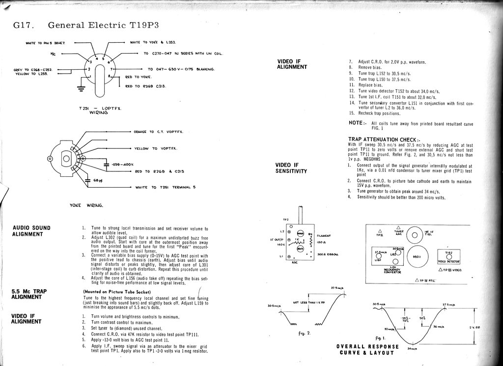
Sound IF, Detector & Output.
The 5.5Mc/s sound IF is taken from the
plate circuit of the video amplifier. This allows the video amplifier to
contribute useful gain for the IF signal. The sound IF amplifier itself
uses a triode of the 14BL11. Using a triode here requires the stage to
be neutralised. This is done by C304, which feeds an out of phase voltage
into the grid. It's an unconventional circuit, but it does work. Presumably
the gain is not quite as high as if a pentode had been used. Another interesting
aspect of design here is that the sound IF transformer is shunt fed from
the triode, which has a plate load of 47k (R305). Normally, the transformer
primary would be carrying the plate current on its own.
The FM signal is detected using one section
of the 17BF11. It is a quadrature detector circuit, and this valve is specifically
designed for this use. In very simple terms, a coil in the suppressor grid
circuit (L302) oscillates at 5.5Mc/s. The incoming FM signal applied to
the control grid is compared to this fixed 5.5Mc/s, and as the frequency
varies, so does the electron stream, and thus the plate current.
The detected output is of sufficient amplitude
to drive the audio output valve directly. Again, feeding the plate resistor
from the 400V boost supply increases the audio level. The output stage
is the power pentode section of the 17BF11. It is interesting that the
bias for this valve relies partly on a bleed resistor from the B+ (R310),
so that the cathode resistor (R309) can be of lower than normal value.
Presumably this was done to avoid using a cathode bypass capacitor, since
the higher the value of an unbypassed cathode resistor, the more negative
feedback there is, and more loss of gain.
Power Supply.
In the U.S. version of this set, the incoming
120V mains is half wave rectified, producing a B+ of 148V. Pi filtering
is used, comprising of L401 and R401, along with three electrolytic capacitors
in the can of C402.
The valve heaters are connected in series
across the 120V supply. No dropper resistor is required, since the valves
have been designed so that their heater voltages add up to 120V.
The Australian version of the set has
a 240V to 120V power transformer added, since 1), Australian technicians
don't like live chassis sets, and 2), a heater dropper resistor would be
required, which would give off excess heat for the heater voltage and current
required. Sets for 200-250V mains with series heaters use 300mA heater
valves, which eases the situation considerably. Unfortunately, adding the
transformer adds noticeably to the overall weight of the set. Even with
my good degree of fitness, I find it difficult to carry.
It is interesting to speculate that if
GE in Australia had modified the rectifier to be full wave, perhaps a smaller
transformer could have been used, since there would not be any DC flowing
through the transformer, as is caused by half wave rectification. DC flowing
through a transformer causes losses from core saturation, and the core
has to be larger (heavier) than if no DC is present.
The T19P3 and T19P4 use the same chassis.