Heater circuit of Emerson CF-255.
Supplying the dial lamps in a series heater
circuit is not simply a matter of connecting the required lamp(s) in series
with the valve heaters. Although both use tungsten filaments, the valve
heaters operate at a much lower temperature (red hot), than the dial lamps
(white hot). This means that valve heaters come up to temperature much
more slowly than the lamp filaments. Their cold resistance takes much longer
to rise, than that of an incandescent lamp.
If a dial lamp is merely connected in
series with a heater string, the lamp will be subjected to over voltage
at switch on. The low resistance of the cold valve heaters causes a much
greater current flow than the incandescent lamp can cope with, and thus
the lamp burns out.
We will look at the various methods which
have been used to overcome this problem, and how in the modern day, the
dial lamps may be supplied where original parts are not available.
1) Shunt Resistor.
The oldest method is to simply connect
the dial lamp(s) in series with the valves, but to include a shunt resistor
connected across the lamp(s). The idea is that the resistor will absorb
the cold surge current. Its value is ideally selected so that the lamp
sees no more than its maximum voltage at switch on. However, the disadvantage
of this scheme is that after the valves warm up, the dial lamp receives
less than normal voltage. This method was commonly used with line cord
resistors.
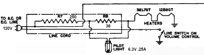
Heater circuit of Emerson CF-255.
In the above circuit of an Emerson CF-255 mantel radio, the valves have 300mA heaters, and their total voltage is 45.1V. In series with them is a 6.3V 250mA dial lamp. This in itself would require a shunt resistor to bypass the additional 50mA. The value of such a resistor would be 126 ohms. However, keeping in mind the switch on surge, the resistor has to be a lot lower than this. In practice, it has to be no more than 39 ohms. (38 ohms shown was measured after the line cord resistor was constructed). When the valves have warmed up, the dial lamp runs at about 4V.
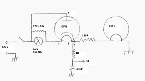
Heater circuit of Perco FM tuner.
In the Perco circuit above, the same arrangement is used, but the heater string is 150mA. The dial lamp is 6.3V 150mA, and the shunt resistor is 120 ohms. When the valves have warmed up, it runs at 4V. Note that this is a modified circuit; since the original did not provide sufficient dial lamp brightness. See the notes on the tapped heater rectifier below.
The shunt resistor should be rated at sufficient power to carry the full heater current if the lamp burns out. Keep in mind, that if this happens, the effective dropper resistance is increased, and the set's performance could deteriorate.
The dial lamp current must be no greater than the heater string current, and the shunt resistor must be low enough to prevent the dial lamp being overloaded, at cold switch on. The higher the voltage across the dropper resistor compared to the valves, the less the surge current will be, and the higher the value of the dial lamp shunt resistor. Because of this, it becomes impractical to use this method in sets where the total heater voltage adds up to the same as, or close to, the mains voltage.
An improvement of this method is to also include the B+ current through the lamp circuit. In this way, as the set warms up and B+ current is drawn, it compensates for that lost by the shunt resistor.
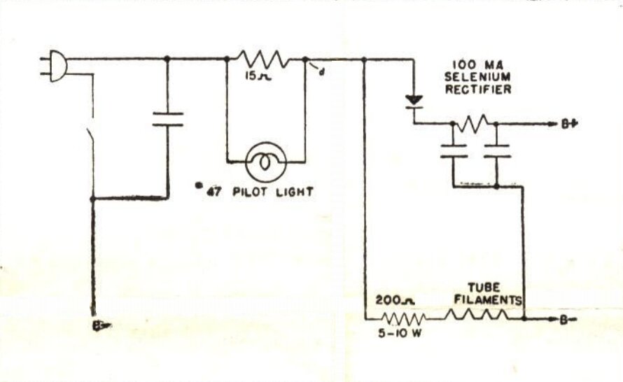
Entire set current flows through dial lamp and shunt resistor.
The above circuit is typical of that provided by manufacturers of selenium rectifiers during the 1950's, and is intended for 150mA series heater circuits. At cold switch on, the 15 ohm resistor will absorb the excess current which would otherwise burn out the lamp. As before, once the valves warm up and the heater current stabilises at 150mA, the lamp will be dim because of the 15 ohm resistor shunting away some of its current. However, in this circuit, the B+ current flows through the lamp as well as the heater current. This extra current makes up for some of the current absorbed by the 15 ohm resistor. Importantly, this extra current flows only when the valves have warmed up, and so the switch on surge is avoided.
Testing this circuit with the Four Valve FM Receiver wasn't very successful, with the dial lamp operating on just under 3V, and that was with a 22 ohm shunt resistor. The problem was the B+ current draw (about 40mA) was not enough to offset the losses in the shunt resistor. It's best suited to applications that draw more current, such as a full size receiver or amplifier.
For those that want to try it, the shunt
resistor can be optimised with a simple calculation. First, measure the
cold heater string resistance. We'll use 270 ohms as an example. If the
supply is 120V, the maximum surge current will be 120 / 270 = 440mA.
Since the maximum lamp current is 150mA,
that means 440 - 150 = 290mA needs to be absorbed by the resistor at switch
on. R = V / I, so R = 6.3 / 0.29 = 21.7 ohms.
Of course, if it turns out the B+ current
is high enough that the lamp voltage is exceeded after warm up, the shunt
resistor needs to be reduced accordingly.
2) Thermistors.
A simple and obvious way to remove the
switch on surge is to include an NTC (Negative Temperature
Coefficient)
thermistor in series with the heater string. The cold resistance of the
thermistor is selected so that the heater string current, when cold, does
not exceed that of the dial lamp. As the current flows through the heater
string, the thermistor warms up. Once fully warmed up, the hot resistance
is much lower, and normal heater current flows. The advantage of this scheme
is that the dial lamp can run at full current when the valves have warmed
up.
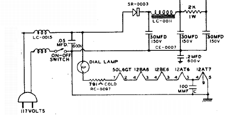
Power supply circuit of Howard 474.
The above circuit shows the B+ power supply and heater circuit for a Howard 474 mantel radio. It uses a selenium rectifier to obtain the B+. The valves are 150mA types. The dial lamp is a No. 47, rated at 6.3V 150mA. The heater voltages add up to 100.4, and with the dial lamp, the total is 106.7V. The remaining 10.3V is dropped across the thermistor. If a fixed resistor was used here, the dial lamp would burn out immediately set was switched on. However, since the cold resistance of the thermistor is 791 ohms, no more than 150mA can flow in the circuit, even if the valve heaters were actually shorted out. Once the thermistor heats up, its resistance falls to around 70 ohms, by which time the valves have warmed up and are drawing their normal 150mA.
Since dial lamp filaments operate at a
much higher temperature than valve heaters, their life is generally shorter.
A shunt resistor may still be connected across the dial lamp circuit to
keep the set operational, should the lamp burn out, or alternatively to
run the lamp at slightly reduced voltage to extend its life.
A refinement of this is to replace this
shunt resistor with another thermistor. This thermistor is of much higher
value than a fixed shunt resistor, which minimises the loss of current
for the lamps.
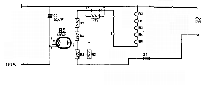
Heater circuit of Philips B3X75U, set for 220V.
Using a Philips B3X75U as an example, the valve heaters (B1 to B5) are wired in series in the usual way. This set uses U series valves with 100mA heaters. The heater dropper resistance is comprised of R3, R4, and R5. Note that R5 is the inrush current limiter thermistor. Z1 is the fuse. R2 is the surge limiter for the rectifier, and is separate to the heater circuit. The dial lamps (L1 and L2) are Philips type 8089D, which are 12V 100mA. They are also in series, but are shunted by R19, which is another NTC thermistor. The cold resistance of this is sufficiently high to have negligible effect on the operation of the lamps, which are operating close to 24V. If, however, one of the lamps goes open circuit, R19 will be exposed to a considerably higher voltage. The current flowing through it will increase to a sufficient level that it heats up and becomes low resistance. Thus, the valve heaters continue to function.
3) Tapped Heater Rectifier.
When 150mA series heater valves were introduced
in the U.S., a new type of rectifier was introduced; the 35Z5. This later
became the 35W4 in seven pin miniature form. The design behind these rectifiers
was one of cost cutting, but also to overcome the switch on surge problem
with dial lamps..
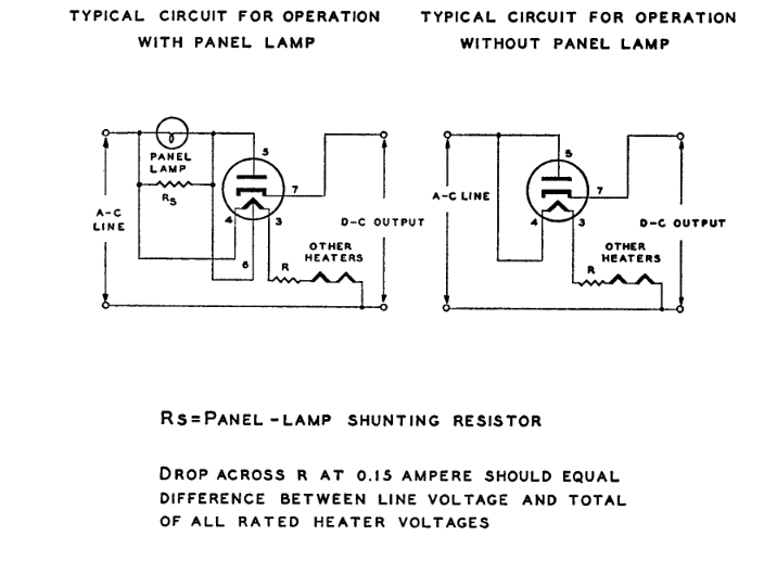
Application circuit and data for the 35W4.
The cost cutting attribute came about from
the fact that it was possible to make a radio with no dropping resistor,
since with typical set design, the sum of the heater voltages using the
150mA valves added up to around 120V. The rectifier valve and dial lamp
also served as a fuse, should there be a B+ overload. The rectifier heater
is tapped, and it is this tapping which supplies the dial lamp, augmented
by the B+ current.
Without a dial (panel) lamp, the rectifier
functions like any other. There is 35V at 150mA across the full heater
(pins 3 & 4). If the voltage is measured at the tapping at pin 6, there
will be 7.5V with respect to pin 4, and 27.5V with respect to pin 3.
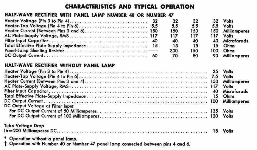
It gets more complicated when a dial lamp is introduced. The intended dial lamp (No. 40 or 47) is a 6.3V type, rated at 150mA. The lamp is connected across the shorter section of heater; i.e., between pins 4 and 6. Referring back to the simple shunt resistor circuit, we can see that the same thing exists here, with the shunt resistor now being the section of heater between pins 4 and 6. Not only does the radio manufacturer eliminate a wire wound resistor, but the heater has the correct temperature coefficient, to prevent the dial lamp being subjected to a switch on surge. The dial lamp thus comes up to normal operating voltage at the same rate as the valves.
Note that the short heater section is rated to work at 7.5V, but runs at 5.5V when loaded by the dial lamp. In this configuration the total heater voltage is 32 instead of 35. It can be seen therefore, that the dial lamp used in this way does rob the 35W4 of some heater power. This is also reflected in the ratings, where the output current is 90mA with the lamp, but 100mA with no lamp.
It can be seen that only a portion of the
150mA gets to the lamp, with the rest consumed by the pin 4 to 6 heater
section. And so, although the switch on surge is eliminated, we're back
to the dial lamp not receiving full voltage. In fact, after warm up, it's
about 3V.
However, a clever trick largely offsets
this. Examining the above circuit on the left, we can see that the plate
of the 35W4 is fed from the mains supply, via the parallel circuit of the
dial lamp and heater tapping. This means that on every positive half cycle,
the plate current is added to that flowing through the lamp and short heater
section. Thus, the lamp voltage is increased to 5.5V.
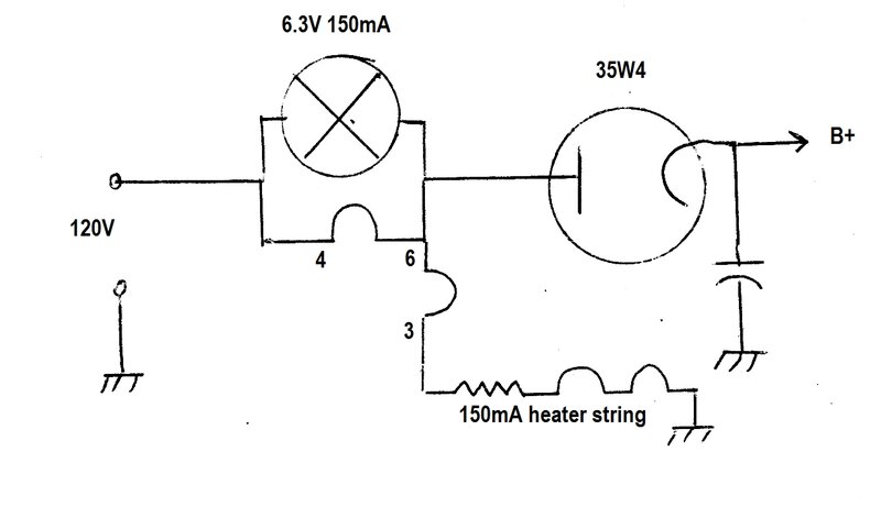
35W4 circuit redrawn to show tapped heater operation. Dial lamp
and short heater section carry entire set current.
Clearly, the B+ current drawn influences
the dial lamp voltage. Where this is above 60mA, a shunt resistor is required
across the lamp, not only to prevent the lamp being exposed to excess voltage,
but also the short heater section.
In applications where the B+ current drawn
is very low, the dial lamp will not achieve usable brightness, and will
need to be powered by one of the alternative circuits. Hence the modification
to the Perco FM tuner, referred to previously.
Further economy of design is achieved with this circuit, since the dial lamp/heater section also takes the function of the surge limiting resistor. This is otherwise required to protect the rectifier cathode from the high peak charging current of the first filter capacitor. Without the dial lamp circuit, a minimum of a 15 ohm resistor is required in series with the plate (or cathode).
Finally, the dial lamp/heater section also acts as a fuse (albeit a rather expensive one), saving the cost of a fuse and fuse holder. If there is a B+ short, excess plate current flows through the dial lamp and short heater section, burning them out. In the modern day, my preference is to install a conventional 60mA fuse in series with the rectifier cathode. Shorts do happen, as my small collection of open circuit tapped heater rectifiers confirm. Given that series heater valves are not common in my part of the world, I regard a fuse as an important part of restoration.
One important warning should be heeded
by owners of sets using this configuration. If the dial lamp burns out,
do not continue using the set. In this situation, the short heater
section carries the entire the B+ current, as well as the
normal rated 150mA heater current, and it burns out.
This is the common cause of an open circuit
between pins 4 and 6 of a 35W4, or pins 2 and 3 of a 35Z5. As an emergency
or temporary fix, it's possible to bridge out the open section and continue
using the rectifier, albeit with reduced efficiency.
If there is a thermistor in series with the valve heaters which has failed, it can be replaced by an appropriate fixed resistor of suitable power rating, and operation will be restored. The surge protection is lost of course, but considering many sets were made without it, and seem to be reliable, it's questionable as to how essential it is. For those sufficiently enthusiastic, a modern thermistor could be used, and even if not of exactly the same characteristic, it would help reducing the switch on surge.
If there are dial lamps as part of the original heater circuit, there are a few options:
Shunt Resistor.
Where most of the mains voltage is across
the dropper resistor, the shunt resistor circuit can be used. While
the dial lamps won't operate on their full voltage, they will usually be
bright enough. At its best, expect around 4V across a 6.3V lamp.
The formula of the shunt resistor is easily
calculated, as previously shown with the circuit where the entire set current
flows through the shunt resistor and dial lamp. To repeat:
First, measure the cold heater string
resistance - that is the total resistance of the valve heaters and any
dropper resistor. We'll use 270 ohms as an example. If the supply is 120V,
the maximum surge current will be 120 / 270 = 440mA.
Since the maximum lamp current is 150mA,
that means 440 - 150 = 290mA needs to be absorbed by the resistor at switch
on. R = V / I, so R = 6.3 / 0.29 = 21.7 ohms.
If the dial lamps are not bright enough, the next variation of the circuit should be tried, where the B+ current also flows through the dial lamp / shunt resistor circuit. Again, the shunt resistor value is calculated the same way, but in this instance may need to be reduced if the B+ current draw is particularly high.
PTC Thermistor.
If the shunt resistor method results in
too low of a voltage across the lamps, another option is to use a PTC (Positive
Temperature
Coefficient) thermistor as the shunt resistor. The cold value of
resistance would be selected to be equal to, or less than, that required
to limit the dial lamp voltage at switch on. The hot resistance would be
as high as possible, and the thermistor warm up time would need to be no
faster than that of the valves. No experiments have been done regarding
this, and the concept is mentioned as a possibility for further experimentation.
Zener Diodes.
Another option is to use zener diodes
across the lamp(s), either on their own, or in conjunction with a shunt
resistor. The zener diodes are connected back to back, and simply function
as a voltage clamp. It is important to remember the difference between
peak and rms voltage here, since the zener diodes will be acting on the
peak voltage. When a lamp is fed from a 6.3V sine wave, it is actually
working on a peak voltage of 1.4 x 6.3 = 8.8V.
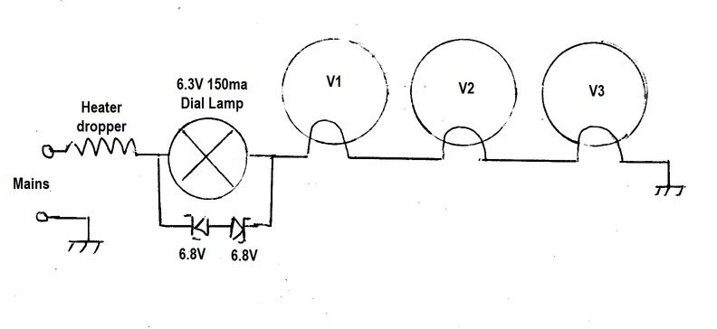
Peak voltage is limited to 7.4V.
When zener diodes are connected back to
back as shown, remember that the clamp voltage is actually the zener voltage,
plus the forward bias voltage of the opposing diode. In the example shown,
this is 6.8 + 0.6 = 7.4V.
The choice of zener diode voltage is more
complicated than it seems, because of the sine wave, and the distortion
introduced when the zener diodes conduct. The lower the voltage at which
the zener diodes conduct, the more the waveform will be distorted towards
a square wave. Even though the peak voltage is clamped, the width of waveform
still increases as the input voltage rises. This means that the rms also
increases. Nevertheless, for practical purposes, and if the zeners are
set to a slight level of clipping at normal running, it is very effective.
Experiments showed that for a 6.3V lamp,
6.8V zeners were the best compromise. The lamp then runs at 5.5V rms when
the circuit has stabilised at 150mA.
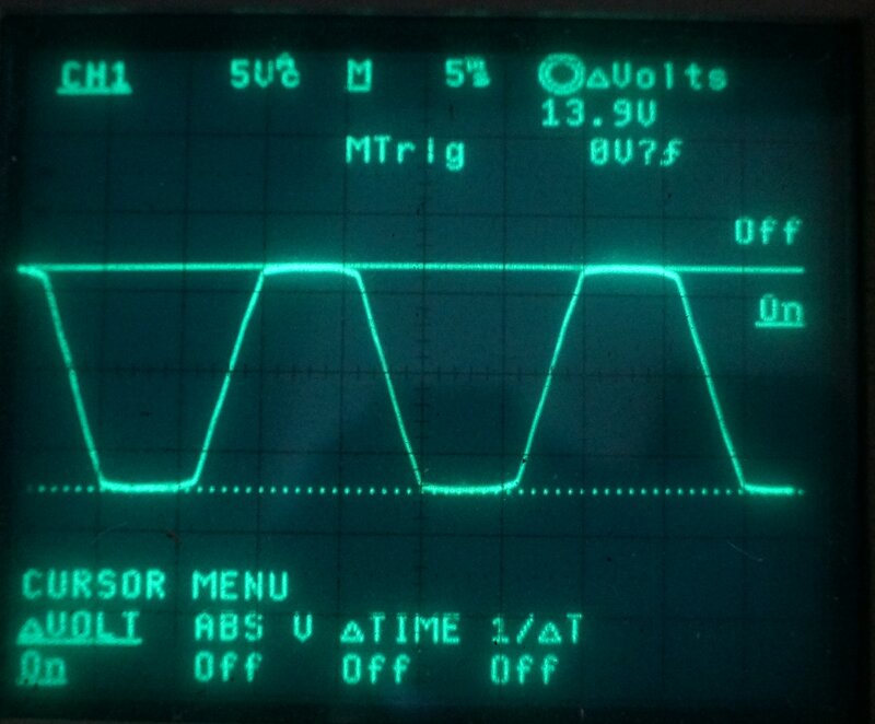
Zener diodes limiting lamp voltage.
The above waveform shows the voltage across
a 6.3V 150mA lamp run from a 14V transformer through a resistor. The zener
diodes were 6.8V. Also tried were 7.5V zener diodes, but the rms voltage
exceeded the lamp voltage under surge conditions.
If you don't mind introducing solid state
devices, this method works very well. In a practical situation, thought
needs to be given to the power rating of the zener diodes. If the lamp
goes open circuit, the zener diodes will carry the entire heater current,
and more so if the set is switched on from cold, with the lamp open circuit.
In this case, 1W rating for the zener diodes would be at their limit for
a 6.3V 150mA lamp going open circuit, but to allow for the switch on surge
with the lamp open, 5W would be a better choice.
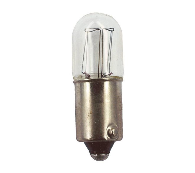
High Voltage Lamp.
Some radios have actually used a mains
voltage light bulb for the dial lamp. Generally, the bulb is of a very
low wattage for obvious reasons. Once sometimes seen in some large Australian
radios was a 240V 15W pilot lamp. U.S. sets have sometimes used a 120V
7W candelabra based bulb. Both these are really too bright for a small
mantel set, but the concept is entirely valid. It is not well known, but
ordinary miniature bayonet bulbs of the same size as the usual 6.3V dial
lamps, are available for 120V. These bulbs are often actually rated at
130 or 150V to give long life on 120V, and draw about 20mA. They are intended
for industrial equipment, but are a very convenient way out of the problem
where the set is designed for 120V, and a thermistor has to be replaced
by a fixed resistor.
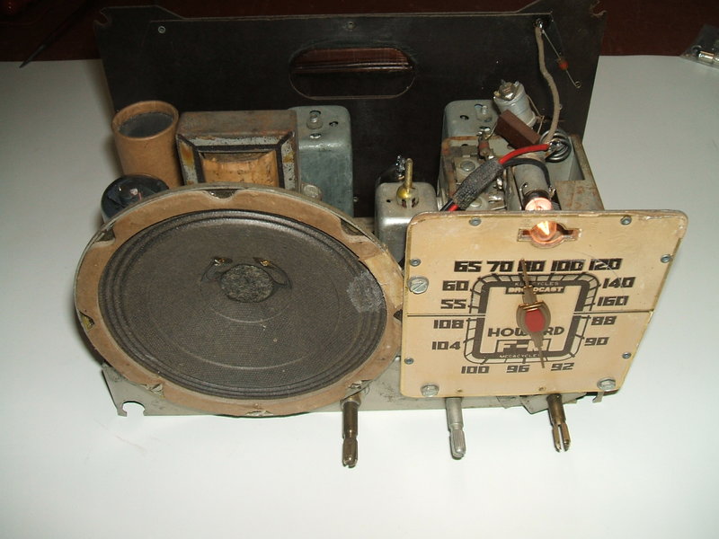
6.3V dial lamp replaced by 130V type in this Howard 474.
The Howard 474 pictured above is a case
in point. The dial lamp was in series with the heater string, which included
a thermistor. Since the thermistor failed, a fixed resistor was used to
replace it. The previous repairer had then simply connected the 6.3V 150mA
dial lamp to the 120V mains supply via an 850 ohm wirewound resistor. While
this worked, there was an extra 20W dissipated in the cabinet, just to
run the dial lamp!
Including the original 6.3V dial lamp,
but with a shunt resistor, was not suitable, because with hardly any dropping
resistance in the circuit, the switch on surge was so high that the shunt
resistor was too low of a value to give sufficient brightness. In this
instance, the lamp was only running at 3V.
The 130V 20mA bulb was the answer in this
situation. More can be read about it here.
Be aware that if considering this type of bulb, the price variation is
considerable, so shop around. In the modern day, with the move away from
incandescent lamps, they will become more difficult to get as time goes
on, so hoard a few for the long term. Also to avoid any overheating problems
or burned dials, keep to less than 2.6W (130V 20mA). Anything more powerful
will also look unnaturally brighter than the original, and be quite distracting.
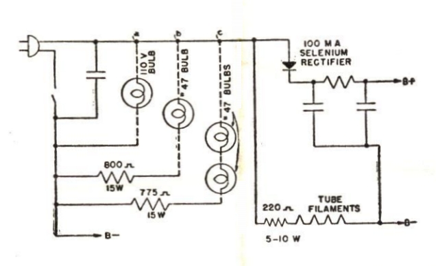
Dial lamps powered directly from mains (110V in this instance).
The above circuit shows options for direct
mains operation of the dial lamps. The mains voltage lamp is obviously
the most efficient. The power dissipation of the dropping resistor when
using 6.3V lamps can be problematic in small cabinets. It is also rather
wasteful of power, especially when it has to be paid for, or is coming
from a battery supply. To illustrate the point, compare a 130V 20mA bulb
across the mains, to a 6.3V 150mA bulb through a resistor. The 130V 20mA
bulb will consume about 2.5W on 120V.
For 120V mains, the 6.3V 150mA bulb via
a resistor still consumes the same amount of current; i.e. 150mA @ 120V,
which equates to 18W. The bulb itself is only consuming just less than
one watt, but the whole circuit uses 7.2 times more power than the brighter
2.5W bulb!
Bear in mind, these kind of circuits were
designed when power was cheap.
LED's.
Dial lamps with bayonet (BA9s) and screw
(E10) bases are now available in LED form. In view of their lower current
consumption, a possibility exists in operating them through a resistor
off the B+, or from the mains supply via a resistor and diode, without
heat dissipation being a problem. Some are available for 120V AC operation
which eliminates that problem. Keep in mind the colour and directional
qualities of LED lamps. An incandescent dial lamp is warm white (about
2700K). The directional qualities are also important, because many LED's
produce a low angle of illumination, and may not light up the dial, despite
being blindingly bright when looked at straight on.