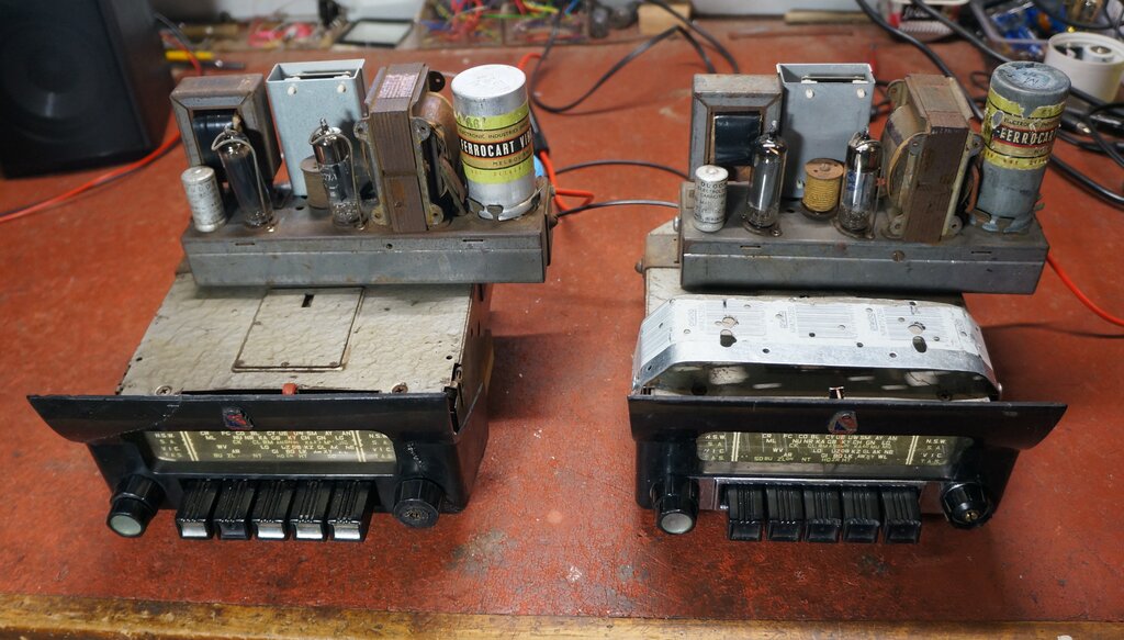
Both these Astor ARM sets have been fitted with Bluetooth modules.
Both these Astor ARM sets have been fitted with Bluetooth modules.
In the modern day, an increasingly common
request with vintage radio restorations is the addition of Bluetooth. Off
air programming is of less quality than it used to be, and many listeners
prefer their own collection of music.
It's quite understandable too. After all,
who wants to listen to a limited and repetitive playlist, interspersed
with advertising, general babble, and the hourly annoyance of 'news'.
External Audio Input.
To date, the requests for external audio
input have been accommodated by the addition of a cable fitted with a 3.5mm
stereo plug. This is connected to an iPod or mobile phone. Essentially,
the incoming audio is simply fed into the volume control of the radio.
The low output impedance of the iPod or mobile phone overrides the higher
impedance of the radio's detector circuit, and thus the radio is silenced
(largely), when the 3.5mm plug is inserted. In instances where radio programs
can still be heard in the background, it's necessary to tune off station.
This avoids the difficulty of adding any additional switches.
The scheme works well enough, but has
the limitation of the external audio device having a 3.5mm socket. Also,
not all such devices work. Some expect to see the low resistance load of
headphones, before they will switch the audio to the output socket. iPods
are also obsolete.
This kind of modification has been described
in the links below:
Unlike many Bluetooth converted vintage car radios which one sees advertised, I do at least insist on retaining the original radio, rather than gutting the whole thing and replacing it with solid state modules. It is an unpleasant thought to know of so many valve car radios gutted, with the parts put in the bin, and modern PCB's installed in their place. Sadly, that is what is commonly done.
Modifying radios can be a controversial thing, since it detracts from what it originally was, visually, and/or how it operates. However, my Bluetooth conversion is really just an addition to the original radio, rather than taking anything something away. The valves and vibrator continue to perform their normal function, along with all the original circuitry of the radio. On that basis, it's an easy matter to remove the Bluetooth, leaving virtually no trace that it was ever there. True, some drilling into the chassis and casing was required, but the sets involved were not exactly pristine museum pieces, or particularly rare.
Modules.
Adding Bluetooth requires the connection
of a module. These are readily available on eBay and usually cost less
than about $40. Construction is invariably a tiny PCB with surface mount
components. It requires a power supply, which might be typically 5 to 12V.
There are left and right audio outputs, which are the usual line level
of about 250mV rms.
And that's how simple it is. The aerial
is usually part of the PCB, so the entire module is self contained. Operation
is a matter of "pairing" the audio source (typically a mobile phone) to
the module. Once the connection is made, any audio played from the mobile
phone will appear at the left and right audio outputs of the module. One
advantage of course, is that the whole thing uses a wireless connection.
Typically, the range might be up to about 10m.
Modules are available both in a bare PCB form, or in an enclosure with power and audio connections already fitted. Types specifically for car use are available, operating from 12V, and include a cable with RCA plugs. This is intended to be plugged into an auxiliary audio input, which apparently exists with some modern car radios. Some modules contain an FM radio and a card reader. Also available are combination amplifiers and speakers (so called Bluetooth speakers), which incorporate everything in the one unit, including a lithium battery for portable use.
Car Radio Use.
For a car radio conversion, a module with
an on board regulator is the most attractive. Space is limited around car
radios, so it's best to have everything on the one PCB. Otherwise, another
PCB with the power supply components and regulator (typically 5V), has
to be also accommodated.
The module could be mounted somewhere
outside of the radio, and connected by wires, or mounted on the radio itself.
Installing the module inside the radio is an enticing thought. However,
once the cover is back on the radio, the signal will be shielded from the
module.
It's really a case by case situation,
as to where the module is best located, since there are so many variations
with car radio design.
The next part of the installation is dealing
with the audio. Conveniently, the line level output from the module is
compatible with the typical triode pentode (e.g. 12AV6 & 12AQ5) audio
stage. This leaves just one thing; how to switch between radio and
Bluetooth?
Electrically, in its simplest form, a
SPDT switch, can select the feed to the radio's volume control from either
the radio's detector or the Bluetooth module. The left and right outputs
from the module are connected together to create a mono signal.
Audio Switching.
The problem is where to put the switch.
Drilling a hole in the side of a vintage radio isn't a nice thing to do,
and with the radio usually mounted behind the dash, it would be inaccessible.
You could extend the audio wires outside of the set, with a switch mounted
on the dashboard, but that's messy. Cable capacitance is also problematic
with the lengths required.
Adapting one of the existing controls
to perform the switching is an interesting idea. For example, a tuning
push button could be selected for the purpose. Similarly, a switch actuated
when the tuning is turned to one end of the dial is another progression
of that idea.
In practice, such ideas, although ingenious,
would require more electronics to be added, as well as possibly intricate
mechanical work.
Ideally, what is wanted is electronic switching, which occurs automatically when the Bluetooth module is paired. Want to listen to the radio? Turn off the pairing. Nice and simple with no external switches.
It turns out that the audio outputs of
different modules behave in different ways. Several modules were obtained
for experimentation. All of them tested so far present a very low impedance
output when the module is operating. In fact, the impedance is low enough
to override the high impedance of the radio's detector circuit. This can
simplify the switching, as shown:
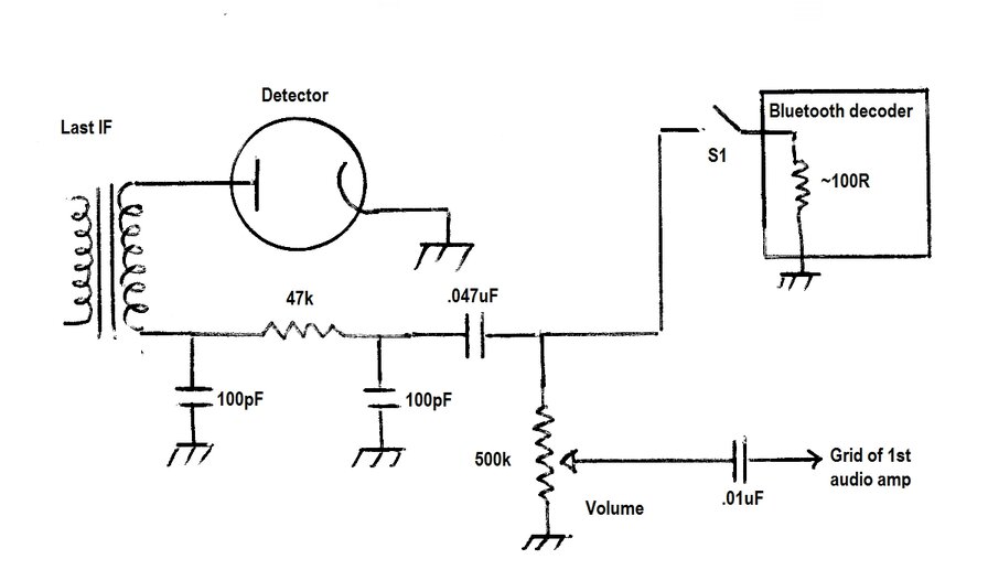
Typical detector circuit, and how Bluetooth module might be connected.
We can see that with a detector impedance
of at least 47k, if a signal source of less than a hundred ohms is connected
across that, then most of the detector voltage will be shunted to earth.
The radio signal will not be heard.
To switch from radio to Bluetooth simply
involves closing S1. The detector signal will be shunted to earth through
the low impedance of the decoder, and overridden with the Bluetooth signal.
S1 could be a physical switch, or ideally, part of the module's circuit,
which comes into operation only during pairing, or playing of files.
In this regard, different modules operate differently. Some always present a low impedance (i.e. no S1), and some present a low impedance only when paired or playing files (S1 is part of their circuit). Others will automatically switch between the decoder and external audio source (S1 is a two way switch). There is no way of knowing how they operate without testing them. That is, unless something obvious like an audio switching relay is present on the module. Three modules were examined.
1) "Bluetooth Speakers" Adaptor.
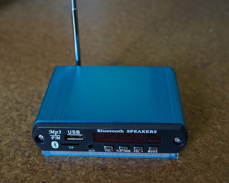
The first adaptor I learned about Bluetooth
with was kindly supplied by fellow enthusiast, Lance Neame, who I've mentioned
in these pages before. It is in a very attractive anodised aluminium case,
and contains an FM receiver, as well as a reader for audio files on a USB
stick or memory card. The audio output is a very high impedance, or open
circuit, until paired. Electrically, this is just what is required. It's
perfect for a domestic valve radio, where it can sit on or near the radio
cabinet. The audio can be fed into the pickup terminals. The FM and card
reader facilities are welcome, especially as the whole thing is provided
with a remote control. The power supply requires a 5V input, which could
be from a USB mains adaptor, or provided from the set, via a regulator
operating off the 6.3V heater supply.
It is less suitable for car radio use,
although of course it could be used, provided it could be accommodated
somewhere; e.g. glove box. There is room inside the case for a 12V to 5V
regulator to be installed.
This particular adaptor has also appeared
without the aluminium case; i.e., just the front panel with PCB. It seems
it was actually designed to be used with amplified speakers. There are
also versions of this which look very similar, but are not actually the
same.
2) Chelink Module.
An attractive module was branded "Chelink",
model CY-LY-018. It was intended for automotive use, being rated at 12
to 24V. Construction was a small plastic case with mounting holes,
and connection to the outside world was through audio cables fitted with
RCA plugs. The usual red and black supply wires also included an inline
fuse.
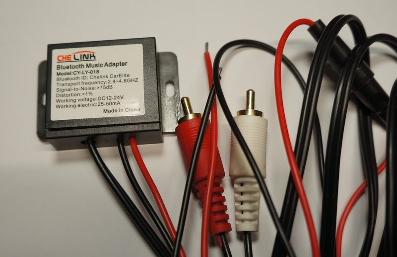
Ideal from a mechanical point of view, but required external switching.
Internally, it comprised the usual surface mount IC. The power supply consists of a surface mount 7805 regulator and polarity protection diode. There is a blue LED which flashes upon power up. It remains on continuously when the module is paired. Interestingly, there was provision for a microphone, its coupling capacitor, and load resistor. These were not fitted, but were suggestive of this module also being used for a mobile phone interface through a car audio system.
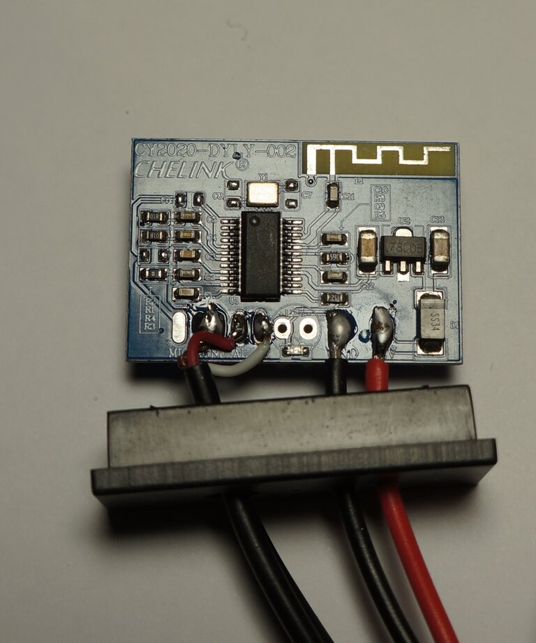
Inside the Chelink module.
This module presented a high impedance / open circuit until it was powered up. It then presented a low impedance regardless of whether it was paired or not. I tried to find data on the IC, but to no avail. What I was looking for was a pin which changed state only during pairing or playing of the audio. Such a control voltage could then control an audio switch based around a relay, a 4053 CMOS switch, or maybe even a simple diode switch. One way to detect the status with what was available, would be to detect when the LED was flashing or on continuously. It's a simple matter to do this, but the amount of extra circuitry, plus the audio switching itself, has to be accommodated somewhere. I'll save this for my future Jeep radio, where I can design the radio to suit the module.
3) Bluetooth 5.0 Receiver Module.
A third module contained a relay to switch
from an external audio source. The relay would switch to Bluetooth only
when audio was being played. It also contained an on board regulator, rated
up to 24V.
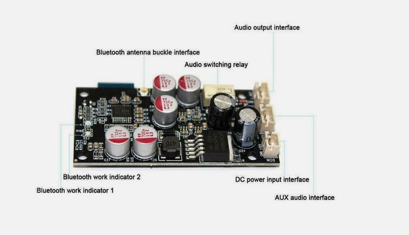
Ideal for this application, and was the module used.
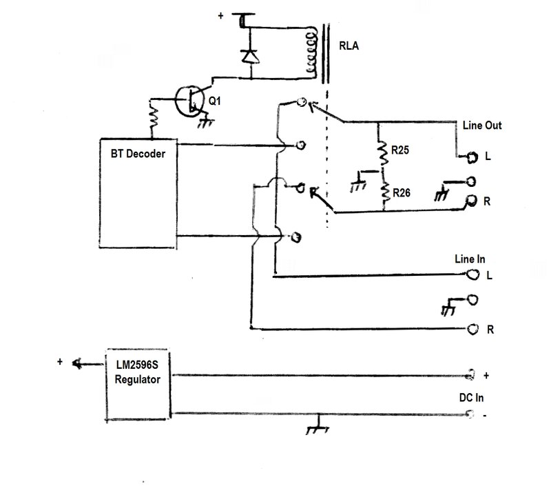
Basic operation of the "Bluetooth 5.0 Receiver Module".
Supply voltage is quoted at 12 to 24V DC.
There is an LM2595S switchmode regulator on the PCB. Blue and Red LED's
show the operating status. When the module is first powered up, the red
and blue LED's alternately flash. When paired, the blue LED remains continuously
lit. The relay switches between the audio from the decoder IC, or the external
audio input. It switches only when the files are being played from the
host device, even if it is already paired.
Note the presence of R25 and R26 (both
20k) permanently connected to the audio output after the relay. For valve
radio use, these need to be removed, as described further on.
A consideration, with whatever module is used, is the connecting cable capacitance. With this module the supplied audio cables had, in total, a capacitance of about 175pF. Depending on how the module is connected, this can cause noticeable treble roll off when used with typical valve radios.
Bluetooth for the Astor ARM Car Radio.
The request was to install Bluetooth in
two Astor ARM car radios. The two sets concerned have been described previously:
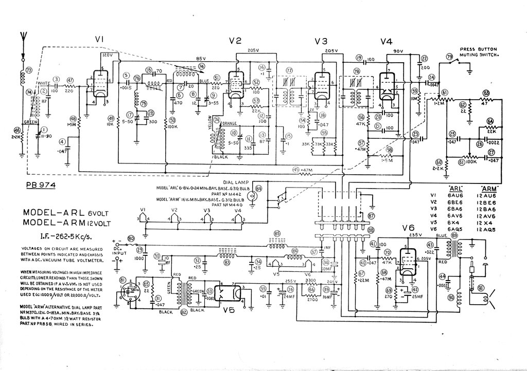
Circuit of the first Astor ARM car radio, to which the module was
fitted . The other set was modified for a 455 kc/s IF, but this has no
effect for the Bluetooth installation.
Out of the two modules which I had which
I had purchased for the project, the relay switched "Bluetooth 5.0 Receiver
Module" was the obvious choice.
Alas, I discovered there was a permanent
load of 20k on the audio output of this module, whether it was powered
up or not. This of course meant that the detector output would be severely
attenuated. Closer investigation revealed two 20k surface mount resistors
(R25 and R26), connected in parallel with the left and right outputs. Presumably,
these were intended as audio coupling capacitor discharge resistors. They're
unnecessary in this application, so were removed.
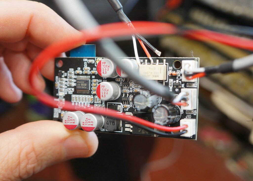
R25 and R26 must be removed. They're visible on the right side of
the PCB in between the connectors.
Things were looking very promising without the resistors. With the module not paired, it could be connected across the volume control without any loading. It turned out that the detector output of the radio did not actually need to go through the relay. The output impedance of the module was low enough to block any off air reception, when the relay switched on. Since both the track and the wiper of the volume control are isolated by capacitors, the module does not alter the DC conditions of the 12AV6, the detector, or the AGC circuits. Similarly, the DC present at the detector does not affect the module.
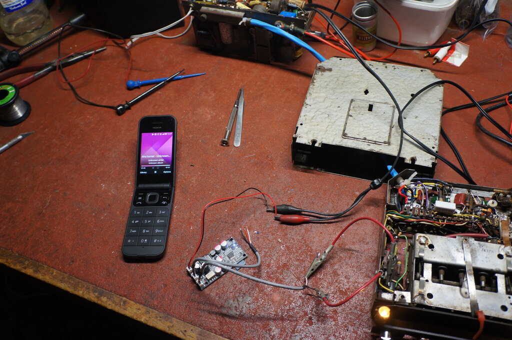
Module temporarily connected into volume control. External audio
input of the module was not used.
Electrically, this was just what I was looking for. Only one audio connection needed to be made to the radio, along with the 12V supply.
It's worth noting also, that any breakdown
inside the 12AV6 valve won't allow damaging current to flow into the module.
The 220k plate resistor will limit the current to about 1mA. However, if
the module is to be fed into a pentode valve beware of a screen grid to
control grid short. Also, a cathode to grid breakdown, where cathode bias
is used means a positive voltage (though probably not harmful to the module)
would appear on the grid terminal. In these situations it would be wise
to include back to back diodes to clamp any undesirable voltage.
A high mu triode with earthed cathode,
and using contact bias, is the safest interface to the power amplifier.
It's true of course, that the coupling capacitor will also provide protection,
but a high enough voltage pulse while the capacitor charges, could be damaging.
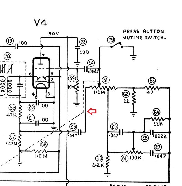
Arrow shows point of connection.
One other thing did become evident, and
that was the cable capacitance of the module. Surprisingly it measured
about 175pF. This was enough to cause a perceptible drop in treble response.
This capacitance is effectively added in parallel with the 100pF IF filter
(C21), so we can see that with the total capacitance is approaching three
times what it should be.
A quick fix was found simply by removing
the unused audio input cable to the module. With the relay off, the input
cable is paralleled to the output cable. The treble roll off was now much
less obvious, and no longer a problem. One could reduce C21 if feeling
particularly pedantic about the matter.
It was just a matter now of working out
the physical logistics of how to mount the module. There was no room inside
the receiver, and the shielding would cause problems anyway. So, the next
thing was to provide an audio connection to the outside. An RCA socket
would be a logical choice for the connector. Where to put it was cause
for a lot of thought. The way the receiver is constructed, with the entire
casing sliding off, makes it impractical to install the socket on case
itself. It would have to be mounted on the chassis, with a matching hole
in the casing.
Unless the socket mount was recessed (more
complicated), it would have to be mounted on the back of the chassis. The
only suitable area was next to where the interconnecting cable comes in.
There's sufficient chassis area to mount a socket here. Alas, drilling
the casing here would not be good, since the casing thickness was double
here, and with a spot weld.
The solution was to make a 20mm x 30mm
bracket and mount it adjacent. It was secured to the chassis with 2.5mm
countersunk screws.
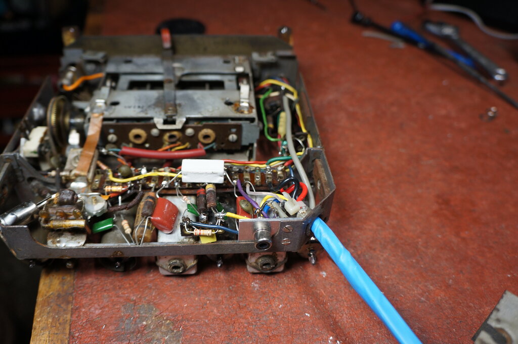
RCA socket just to the left of the blue cable.
I used the lowest capacitance cable I had to connect the RCA socket to the volume control. The shield is earthed only at the RCA socket to avoid earth loop problems.
Where to Mount the Module.
This probably caused more thought than
anything else with the whole project. I don't know behind the dash of an
FE Holden, so I had no idea what places on the radio to mount it without
something getting in the way. Also, what to enclose the module in was another
consideration.
At first, I had ideas of a plastic box
screwed to the the vibrator transformer since there are unused mounting
holes available. It would stick out the back, or towards the speaker, depending
which side of the transformer I mounted it. The possibility of high voltage
radiation from the transformer affecting the module was also of concern.
And it then it came to me - there's two
chassis mount electrolytics on the power supply chassis which are no longer
used. If these were removed, it would provide just the right amount of
space. Looking at available plastic cases didn't come up with anything
which I thought was optimum. In the end I just made up a steel bracket
and secured it to the chassis with self tapping screws. It was the perfect
solution. The 12V wires were run underneath and connected to the heater
supply.
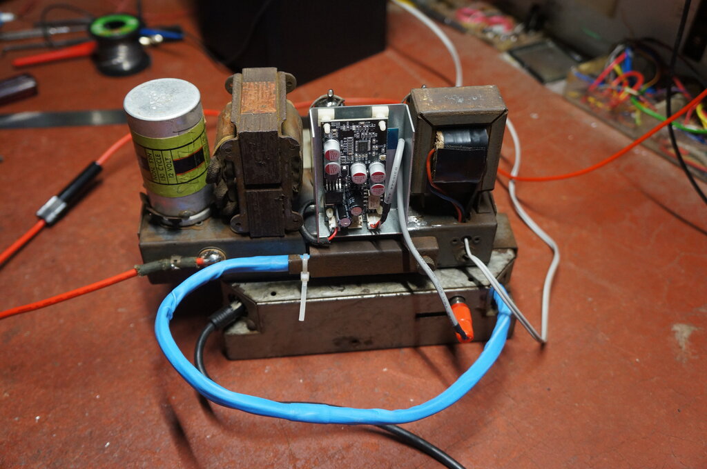
Bluetooth conversion successful!
There was some vibrator buzz noticeable now, which I assumed to be the result of an earth loop. This was confirmed by powering the module from an external supply, whereupon it was quiet. The problem was fixed by installing a 27 ohm resistor in the 12V feed to the module.
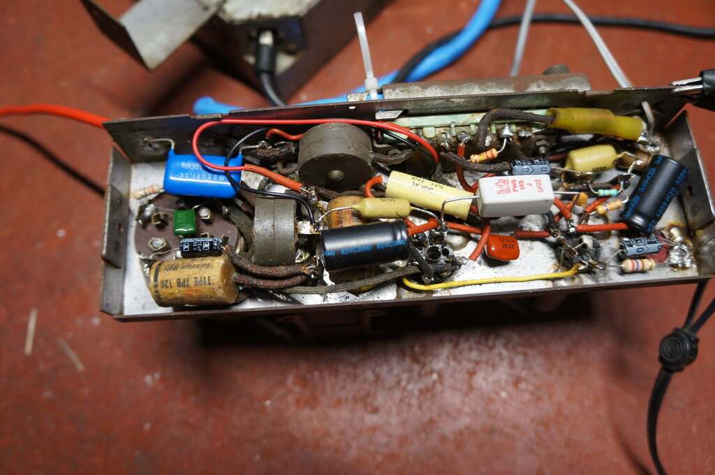
27 ohm resistor is under red cambric tubing near the blue capacitor.
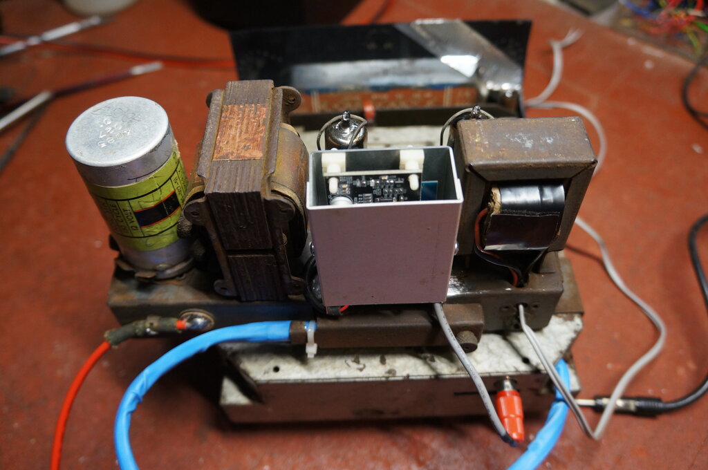
Cover made up to protect PCB.
With that done, the other ARM was modified in exactly the same way. Covers were made up to protect the Bluetooth modules. It would be too easy for a stray wire behind the dash to touch something on the PCB. Of course, it's necessary to allow the signal into the modules, so they were left open at the ends.
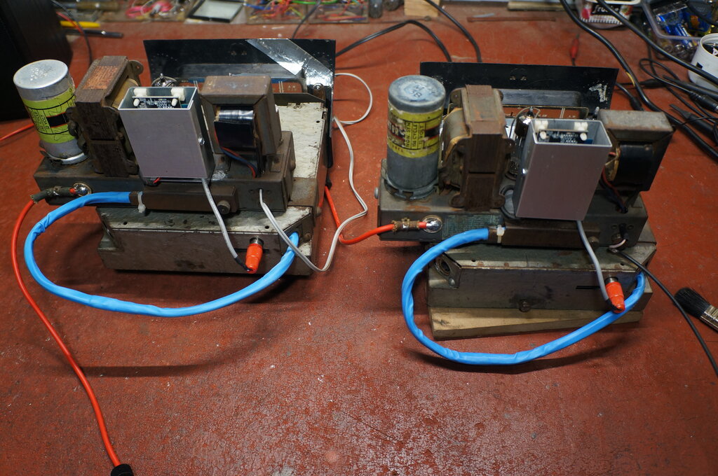
Modules installed for both sets.
For 6V Operation.
It should be possible to use a Bluetooth
module with a 6V car radio as described. However, depending on what the
module chosen actually requires for operating voltage, some modification
might be required. A 7805 regulator won't provide enough headroom, even
with the car's generator charging. Low dropout 5V regulators are widely
available, and are a solution where the module uses a 5V supply rail. Other
schemes involve using the output valve cathode current, where the module
draws less than the valve (typically around 35mA). Perhaps simplest are
pre-assembled regulator modules, to convert 6V to whatever the Bluetooth
module requires.
This will be further investigated when
the Jeep radio is designed and built.