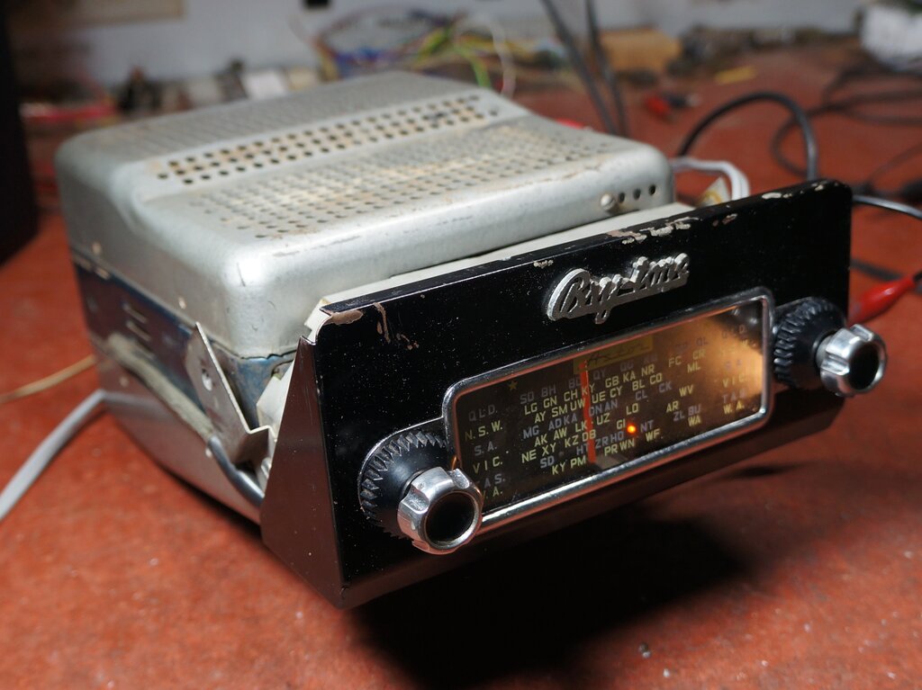
The script above the dial says "Bry-tone", after Brylaw motors who were Jaguar agents in Melbourne.
The script above the dial says "Bry-tone", after Brylaw motors who
were Jaguar agents in Melbourne.
This set came to me for restoration from
an owner of a 1955 XK140 Jaguar. The set was in use until 1962. The SR/SS
was the next development from the RL/RM,
and electrically the two are much the same, and have the same valve line-up.
I would recommend reading that article first, for a background to this
set.
As is usual with Astor car radios, the
second letter of the model designation indicates the supply voltage. SR
is the 6 volt version, and the SS is for 12V. The significant difference
between the SR/SS and its predecessor is the solenoid operated "Selectomatic"
tuning unit. This proved to be the most difficult and challenging part
of the restoration.
As a slight change to previous restoration articles, I will start with a summary of the chronological order of the work done. It will perhaps give an idea of the time taken for such a job.
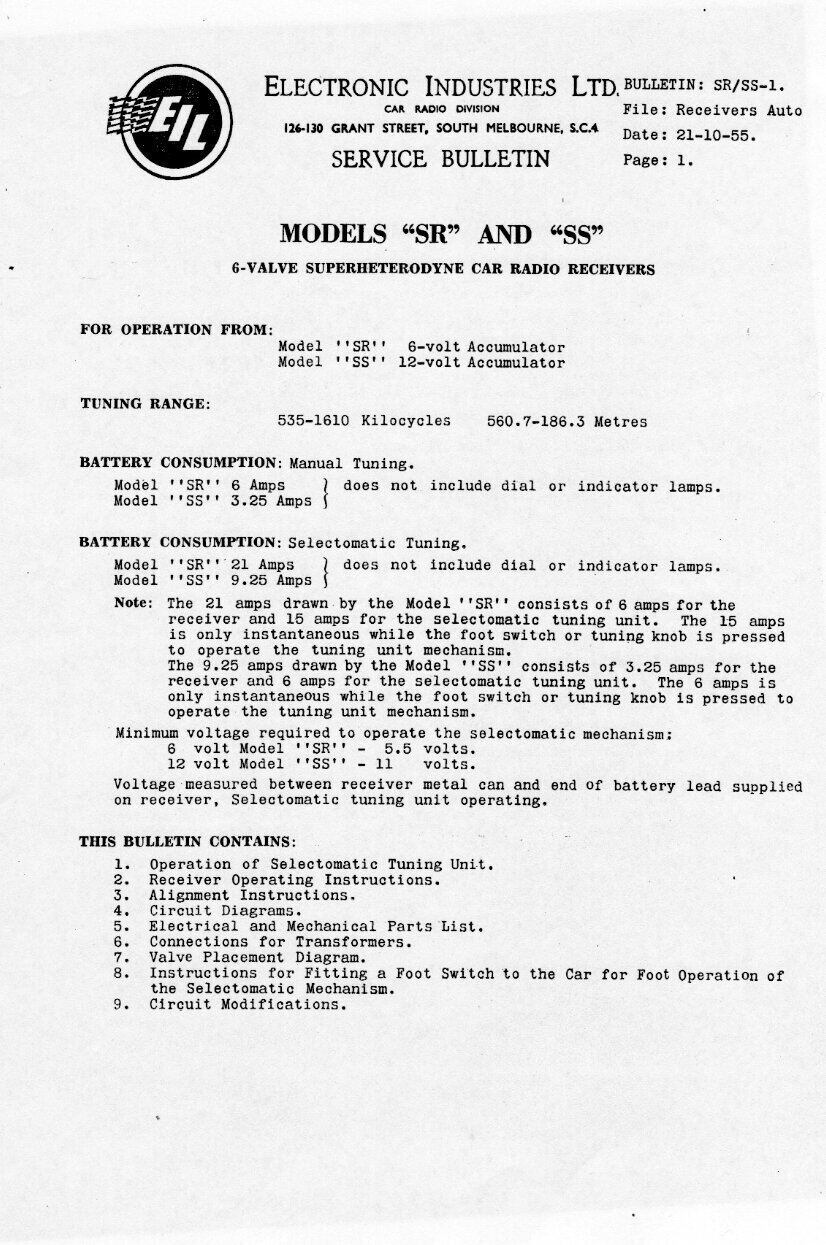
Circuit of the SS. Model SR is the same but with the usual modification
to the heater circuit, and vibrator and transformer.
As can be seen, the design is based on the RM, so details will not be repeated here. The main difference is all in the tuning unit and control head. As with the RM, note that if a 6AN7A is used to replace the 6AN7, the 100R shunt resistor (R62) must be removed to compensate for the difference in heater current. One point of note is the 10M resistor, R40. This was not included in the RL/RM. Its function is for AVC delay. That is, to ensure gain of the receiver is maximum when signals are weak.
Simple AVC.
Under normal conditions when the receiver
is tuned to a station, a degree of negative voltage is produced by the
detector diode at pin 6 of the 6AV6. This is filtered in the normal way
by R43 (1M) and C9 (.05uF), to remove the audio component. As signal strength
increases, so does the negative voltage. Since this negative voltage is
applied to the control grids of the RF amplifier and mixer, the gain of
the receiver is proportionally reduced. Thus, the volume is reduced as
the signal strength increases. The resulting effect is that the volume
remains relatively constant over a wide range of signal strength. Particularly
with a car radio, signal strength will fluctuate as the car is driven along
near buildings, under bridges etc., and as the car is driven further or
closer to the transmitter.
What I have just described is a typical
simple AVC circuit, as used in the RM.
Delayed AVC.
The simple AVC circuit just described
has a limitation in areas of low signal strength. With very weak signals,
AVC control voltage will be developed because the receiver can't differentiate
a weak signal from atmospheric noise. Even with no signal input, there
will also be some AVC voltage developed because of internal receiver noise.
By this, we can see the AVC so developed will reduce the gain, just when
we don't want it to be! The solution for this is the delayed AVC circuit.
It prevents the AVC negative voltage being developed until the signal reaches
a certain strength, when a reduction in gain does become desirable.
The delay circuit in the SS is actually
more commonly used in television receivers than radios, but there is no
reason not to use it. This is where the 10M resistor (R40) comes into operation.
It is connected between the AVC line, and a positive voltage, which in
this case is the +9V available at the 6AQ5 cathode. The value of R40 is
such that it just cancels out the negative AVC voltage produced, until
the signal strength reaches the required amount. When the signal is strong,
the current developed by the AVC rectifier (detector diode), is much greater
than that flowing through the 10M, and the AVC line goes negative, thus
reducing gain. Positive grid voltage on the controlled valves is undesirable,
and could conceivably occur under weak reception conditions, or if the
receiver is off station. To prevent this, a clamp diode is provided, at
pin 5 of the 6AV6. If the AVC line starts to go positive, this diode conducts,
shorting any positive voltage to earth.
More commonly used in radios is a delay circuit using a fixed negative voltage, usually obtained from a back bias circuit in the power supply. This prevents the AVC rectifier conducting until the signal strength reaches a high enough amplitude.
All original components.
All the original wax dipped paper capacitors
were present, along with the IRC carbon resistors. As mentioned many times
previously, these are the weak points of any vintage electronics. The capacitors
absorb moisture and become electrically leaky, and the resistors drift
high in value. Electrolytic capacitors are chemically unstable and can
dry out, losing capacitance. Mica capacitors are also now becoming problematic,
as the silver migrates across the mica insulator. Many intermittent faults
are caused by mica capacitors. Obviously, a radio with components functioning
with different characteristics than originally designed for, cannot hope
to work properly, and in fact some damage is quite possible.
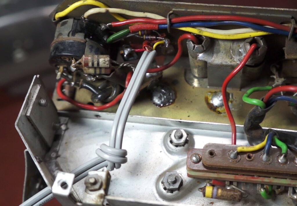
Astor still used rubber cover wire at
the time these radios were built, despite PVC being available at the time,
and this goes brittle. Crumbling insulation in car radio wiring is not
good, since vibration could lead to short circuits.
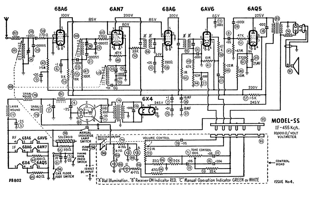
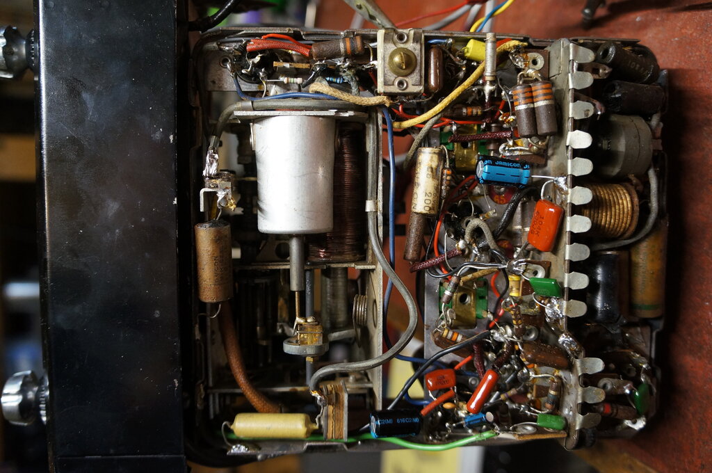
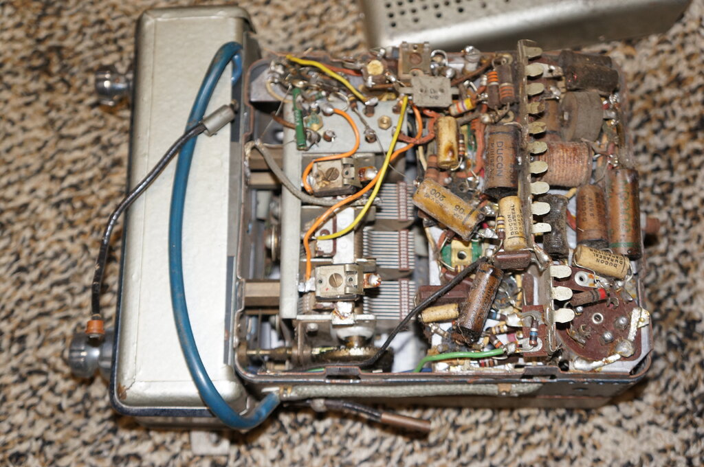
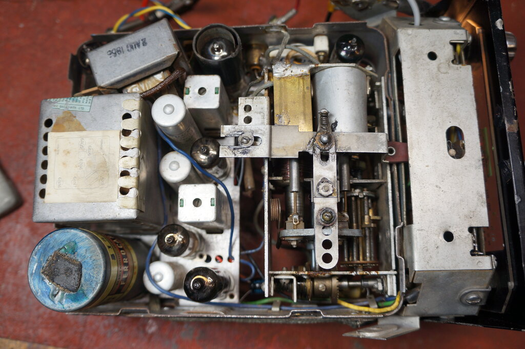
Half of the radio is taken up by the tuning unit.
The Ferrocart PM238 vibrator looked original, and given the radio had only been used for six years, probably was. No doubt it would require the usual contact cleaning and adjustment. Cosmetically, the radio was among the best I've seen. It was very clean inside, and obviously well looked after.
Service Access.
One has to wonder about the people that
designed these sets. Did they really think that resistors and capacitors
were so good that they'd never have to be replaced? Or was it a case of
being told to modify an RM to fit the solenoid operated tuning unit, and
just cram the remaining components into what space remained? And like most
manufacturers, Astor also liked to twist component leads around tags before
soldering. As I've said elsewhere, I have never seen a failed joint
where the wire was simply placed through the tag and soldered.
I do realise that often the component
placement was done as a separate operation to the soldering, with some
manufacturers. This was done to keep the components in place, prior to
soldering on another part of the production line. And admittedly, when
these things were new, the capacitors and resistors had a long time to
go before they would all start deteriorating.
A lot of the time in doing the rewiring,
recapping, and re-resistoring, is actually taken up unpicking the leads
from the tags. Many technicians simply cut the old components off and dabbed
the new ones on the tag with solder. This looks ugly, with numerous cut
wires still attached, and with the new component leads not actually threaded
through the tag. It's quick and easy, which is why it was commonly done,
when the motive is profit.
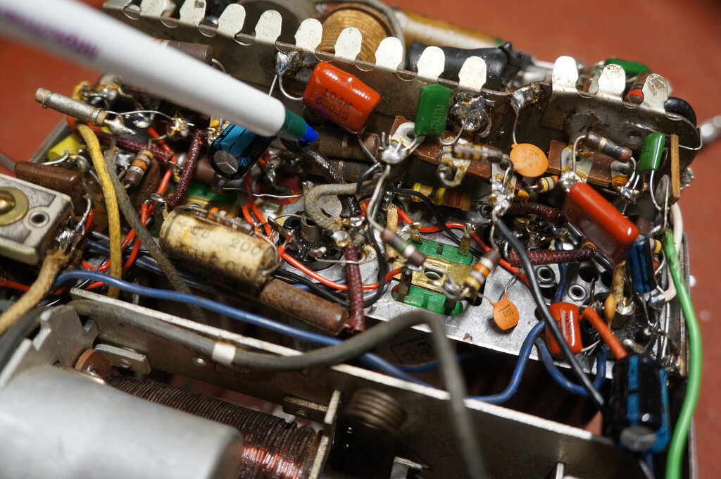
In the SS, two tagstrips have to be removed to access the components underneath. Some of the 6AN7 components, in particular R52, C6, and C14 can only be accessed with this tagstrip shown below removed. A Scope iron is required to get the chassis connection hot enough to desolder the tagstrip from the chassis.
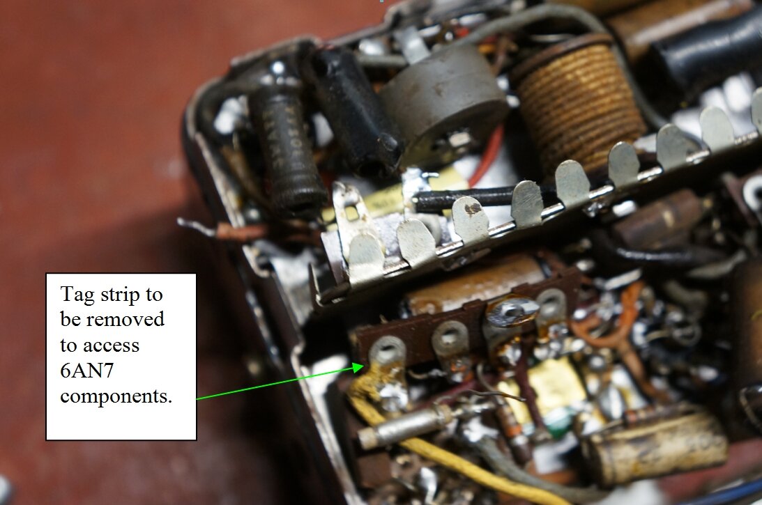
To access the components around the 6AN7, this tagstrip has to be
removed the chassis.
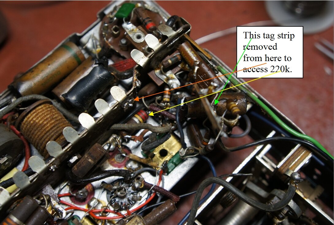
To access the 220k 6AV6 plate resistor, the tagstrip above has to
be removed.
At the other end, to access some of the 6AV6 components, in particular R46 (220k) and C23 (200pF), another tagstrip requires desoldering from the chassis.
New components and wiring installed.
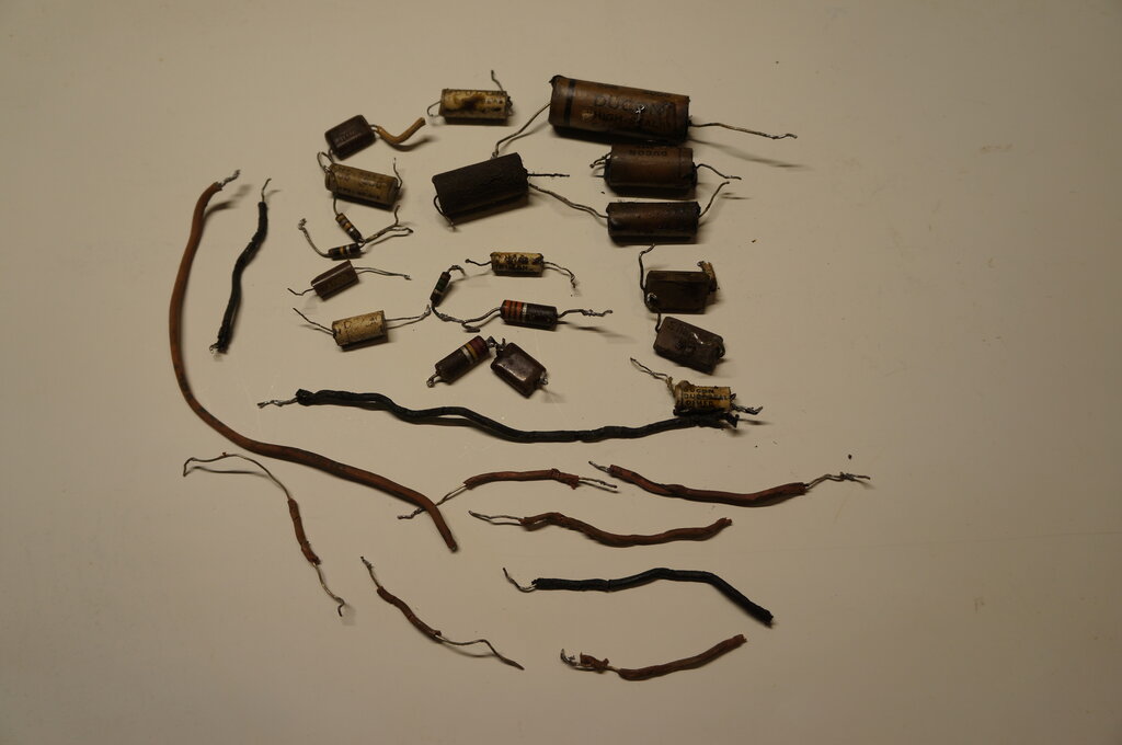
Wiring, resistors, and capacitors replaced.
The electrolytic capacitors were still
good, and had this been my own radio, I would have left things as they
were. However, since they could go open circuit at a later date,
I paralleled new ones across them. The paper condenser for the 6BA6 IF
amplifier cathode bypass was not replaced since any leakage is minor compared
to the 390R cathode resistor. Similarly, the RF bypass capacitors on the
12V supply were left in situ.
Three mica capacitors were replaced since
they have B+ across them. These are C29, C23, and C20.
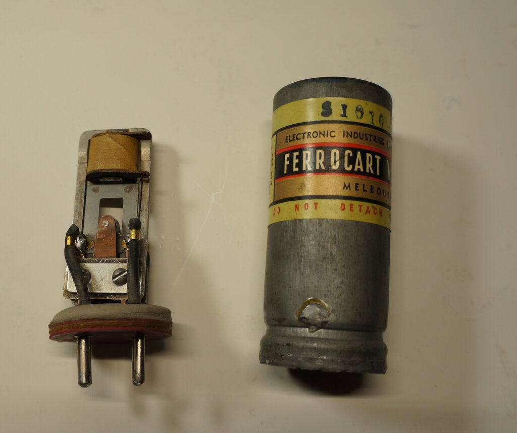
Vibrator opened up.
I have discussed Ferrocart vibrators and
their characteristics here.
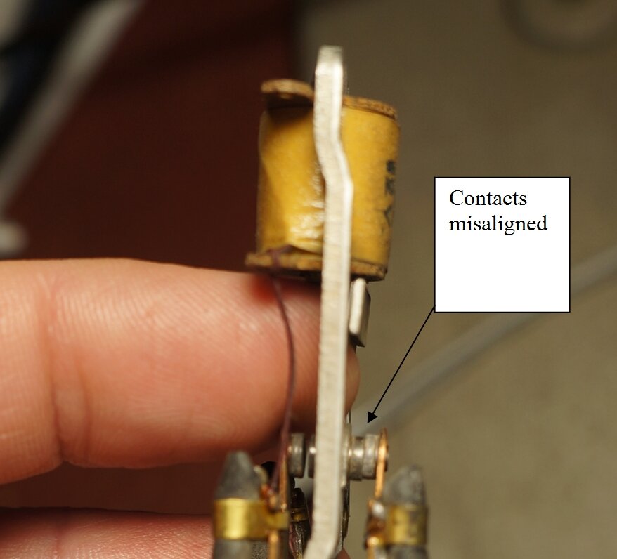
With the vibrator opened up, I can see
why it would never have started. The oxide was quite thick on the contacts,
but once scraped off, the contacts were seen to be in excellent condition.
It looked like it had very little use. Nevertheless, looks were deceiving,
and quite a bit of work had to be done. While the vibrator now started,
the duty cycle was much lower than it should be. Also, the contacts appeared
to be dirty in the electrical sense. It was noted that the inertia contacts
were not perfectly aligned. Having learned that Astor's quality control
in assembling these vibrators was sometimes lacking, this was nothing surprising.
The vibrator was dismantled and the contacts cleaned with 600 grade sandpaper. They actually didn't need much. With that done, next was to decrease the contact gap. This was done by swapping mica insulators around to get the right spacing. Despite a good gap being obtained, the vibrator was now much more voltage sensitive.
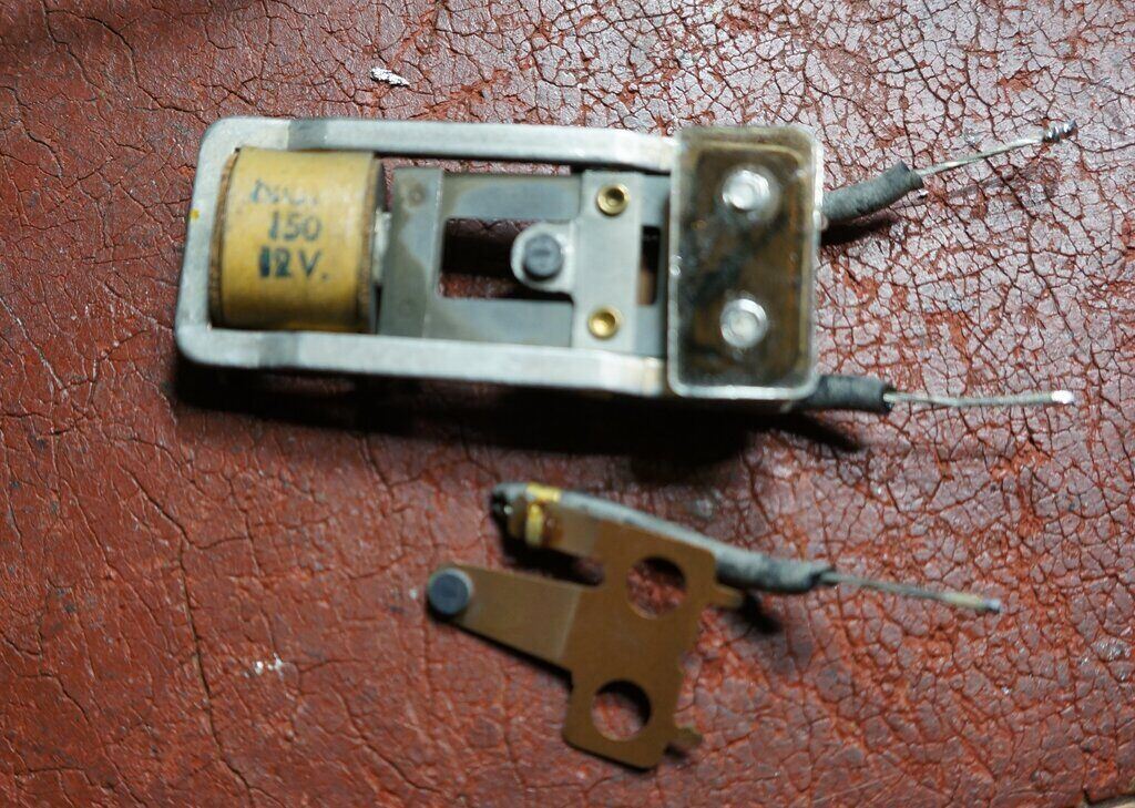
Contact spacing is best adjusted by changing the thickness of the
mica insulators.
While it would start vibrating at much
less than 12V, as the voltage was increased the vibration became erratic
and weaker. As the voltage was increased further, the vibrator suddenly
started operating at a much higher frequency, with less reed swing - to
the point it worked in half wave. I've seen this before where the contact
rivets are loose, but they weren't in this case. I had noticed a slight
twist in the frame, and straightening this actually made it worse.
What else? For a short reed swing, that
implied the pull contact was making too early, resulting in not enough
inertia. This is dependent on the planar distance between the driver coil
core and the reed weight. Sure enough, comparing with other Ferrocart vibrators
showed the gap was too close; in fact the coil core was almost over the
reed weight. Adjusting for a slight gap fixed it, and excellent vibration
was obtained over the normal voltage range.
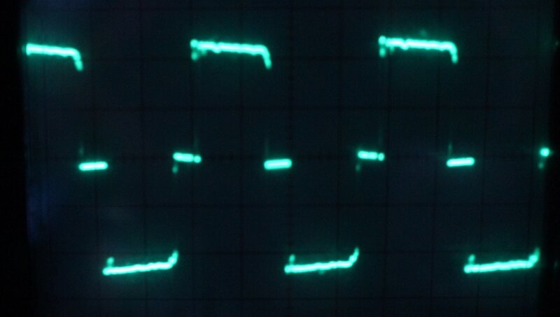
Excellent waveform into resistive load.
As usual, I tested the vibrator on the
test
panel to see that the contact condition was good, and the duty cycle
was around 80%.
The vibrator was reinstalled in the radio,
and again the waveform across the primary was as it should be.
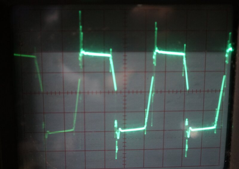
Waveform across transformer primary.
No arcing was present, and the slope of
the waveform was as it should be. This indicates that the contact gap of
the vibrator has been set correctly, and the timing (buffer) capacitor
is the correct value.
The radio was now alive and picking up
stations.
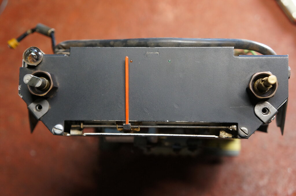
It looks innocent enough, but until the dial pointer is removed,
access to the inside of the control head is impossible. Note the rod soldered
at the right side end.
Amazingly, the rod on which the dial pointer slides has to be removed. This entails desoldering its support at one end. Then, a spring clip has to be removed from the pivot by which the pointer connects to the tuning mechanism. The whole thing is a nightmare, and whoever has to change the two light bulbs inside the control head has my sympathy.
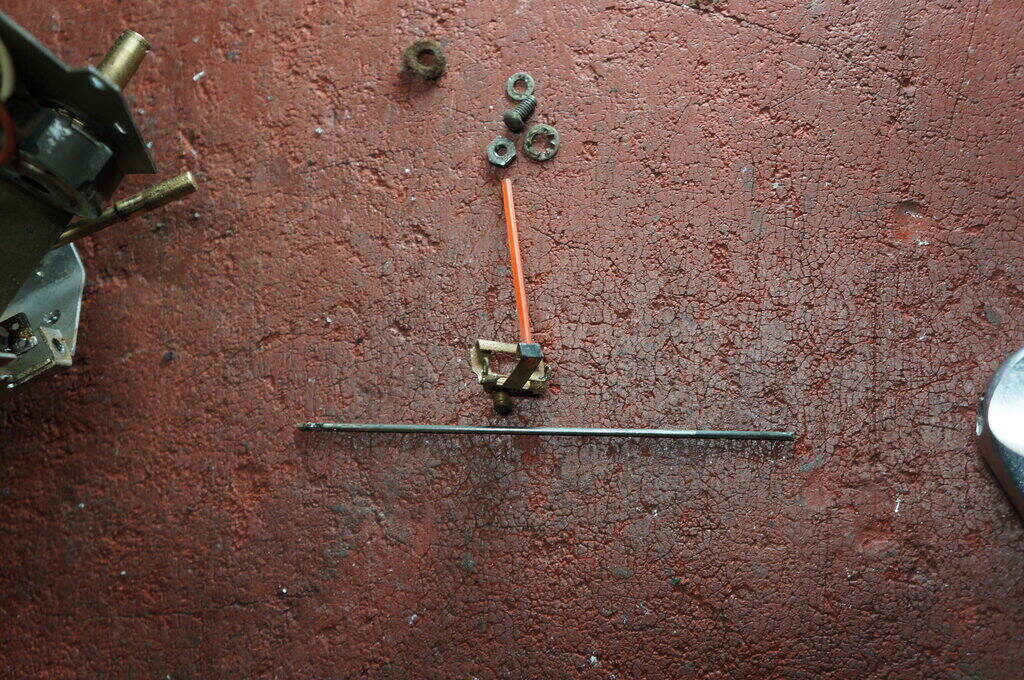
Dial pointer removed.
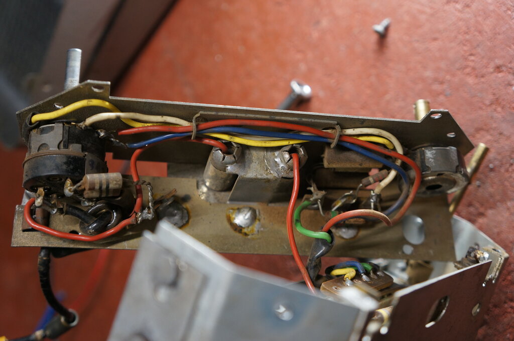
Pity the poor person who has to change the two light bulbs. On/off
volume at left, and tone control at right.
It appears the 4.7R resistor for the 'power'
light has been replaced with two 10R's in parallel. You can see them at
the left. They are an English type of resistor which Astor did not, to
my knowledge, ever use. Also the soldering quality was lacking, with one
end of the resistors barely holding on the tagstrip.
The capacitors in the control head are
only for the feedback circuit, and in view of the low resistance circuit
associated with them, there is no need to replace them. Any leakage will
have no effect.
One thing that had to be done was to install
the missing .05uF (C39) in series with the volume control. Unlike the CS
that I worked on recently, which did have the capacitor installed but not
shown on the circuit, this SS was the other way round. However, the capacitor
should be there, since it isolates the volume control from the DC developed
by the detector, as well as preventing the volume control's DC resistance
loading down the AVC circuit.
Furthermore, adding the external audio
input requires that any DC be isolated from the audio and AVC circuitry.
The external audio input was exactly as
per the RM that I restored recently, except this time I used 470R resistors,
instead of 560R, for the stereo to mono mixer, only because they were to
hand. The value is not critical.
Stereo audio cable provides external input. New .047uF installed
in blue wire to volume control.
As with the audio input added to the RM, switching between the radio and audio source is automatic when the plug is inserted to the audio source. This is because the detector circuit of the radio is high impedance, and is loaded down by the low impedance of the audio source. If there is any radio breakthrough, the set can simply tuned off station.
One of the six turret positions is designated for manual tuning (although it can be used as a preset). The lead screw for this position is coarser, enabling faster tuning from one of the band to the other, and the gear which engages to the tuning knob is larger. Also, when this position is selected, a set of contacts held apart by a notched disc on the turret shaft make connection, and the white light on the dial face illuminates.
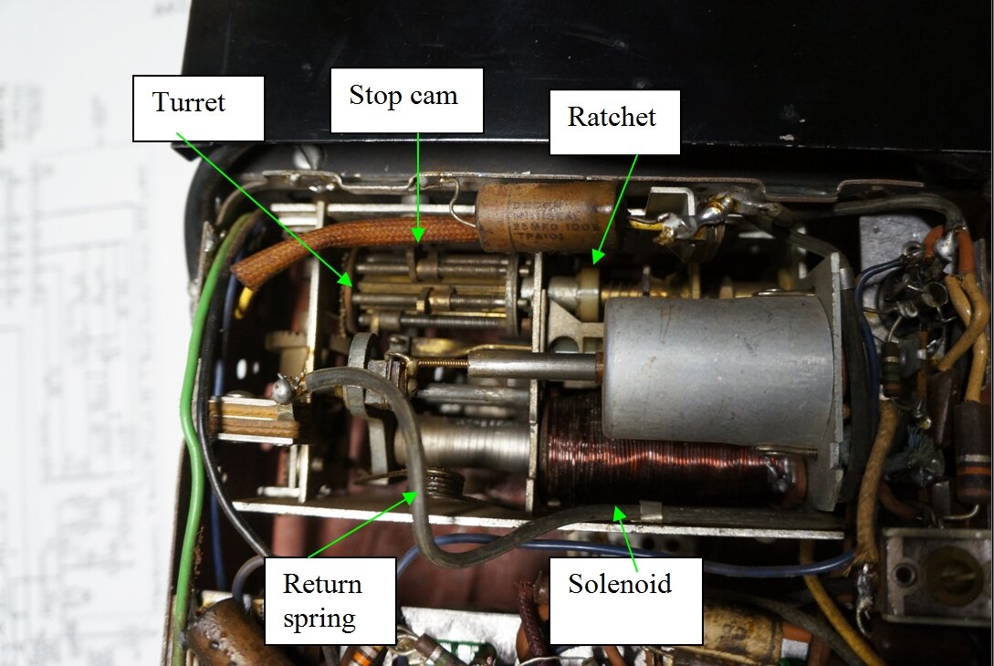
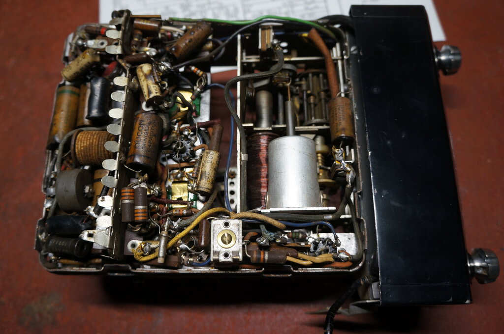
Components of the Selectomatic tuner.
The tuning shaft has three positions, in
that it is pushed all the way in to actuate the solenoid, or pulled out
when presetting the stations. The middle position is the default, and only
engages with the 'manual' lead screw of the turret.
No doubt, Astor copied this design from
a U.S. manufacturer, and the first mention I've found of it is in 1950.
As the radio came to me, the turret had been disabled by a piece of galvanised steel soldered in position so that it prevented rotation away from the manual position. Another piece had been soldered at the back of the tuning shaft to prevent it being pushed in to engage the solenoid contact. The .25uF capacitor across this contact had been removed, as had the connection to the foot switch. Also, the contacts for the 'manual' light had been bridged with solder. The owner advised me there was no foot switch in the car from where the radio came, so I did not need to restore this connection. The owner was also keen to have the tuner restored to operating condition. I said that I'd see what I could do...
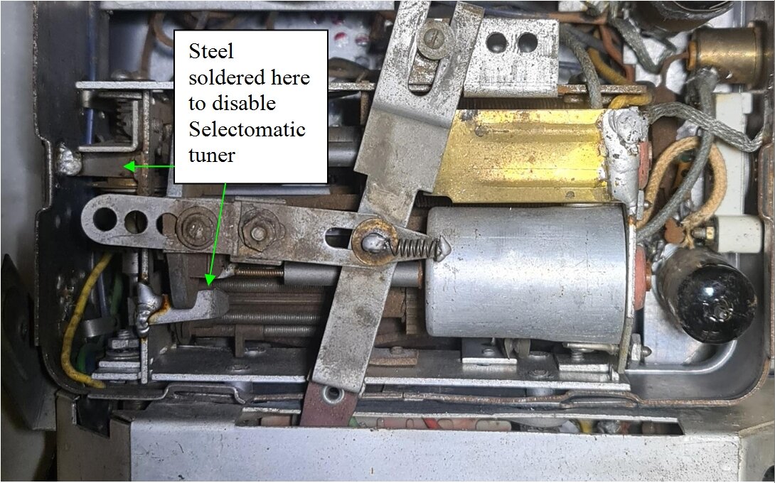
Pieces of steel soldered in position to disable Selectomatic tuner.
Restoring the Selectomatic Tuner.
It took a bit of reading the operating
instructions, and examining the tuning unit to get an idea of how it should
work. To start with, the piece of steel soldered in to disable the turret
was removed. 12V was applied to the solenoid, which sucked the core in,
but nothing else.
The ratchet mechanism is rotated due to
a slot which rotates when a brass bar with a twist is pushed into it. You
can see the twisted brass bar between the turret and the ferrite slug of
the tuning coil in the above photo.
When the ratchet is actuated thus, the
turret moves around one position, and when the solenoid is released, the
particular lead screw stop cam limits how far the solenoid core travels
in the return position.
The turret is supported at one end by
a ball bearing. This was quite loose, so it was tightened to begin with.
Unfortunately, access to do so is poor, and it would seem the intention
is for the tuning unit to be removed from the radio to do this.
The piece of steel was removed from behind
the tuning shaft to enable the switch contacts to work.
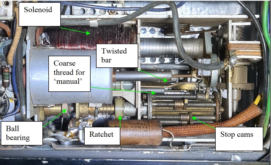
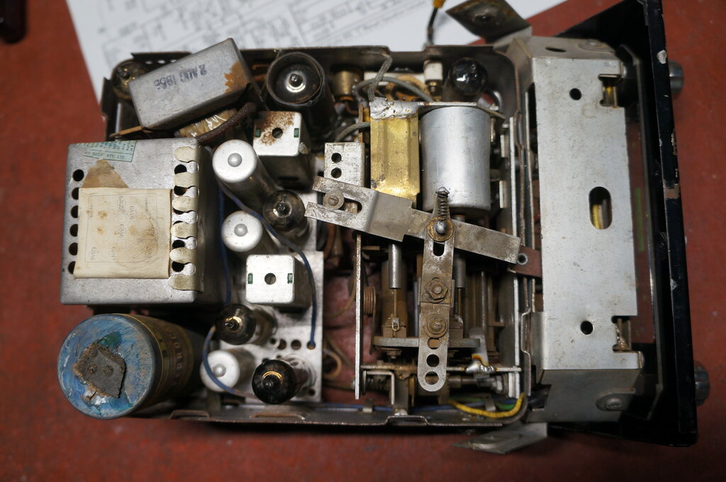
Another view showing the twisted bar which drives the ratchet, and
the ball bearing which supports the turret. Note the difference in pitch
between the 'manual' and 'preset' lead screws.
With something like this, the first thing is to clean the dried oil and grease off, since over time this congeals and becomes sticky. It's obvious from the ratchet that operation has to be quick and unimpeded for it to work. With CRC and light oil to lubricate everything, the solenoid operation was now pretty good, but still the ratchet wouldn't rotate. I had a horrible feeling that maybe the slot in the ratchet had worn and it would never work again. As it turned out, the brass bar and the ratchet needed even more cleaning and lubrication. Something was beginning to happen and I got a few rotations out of it before it jammed up again. At this point I thought I'd examine my own SS to compare its tuner. That was quite a surprise:
The Selectomatic tuner wasn't liked by the person who repaired this
SS.
Someone had completely removed the Selectomatic
tuner and replaced it with a home made manually tuned substitute. They'd
gone to considerable effort too - because when I acquired this radio quite
some years ago, I had not noticed anything unusual. I was not aware of
the SS having a solenoid operated tuner at the time. A close look revealed
a hand made chassis to mount the tuning condenser and coils upon. The whole
thing was actually very well done, and I have no intention of restoring
it to original - not that I have the parts to do so anyway.
This, along with the problems I was experiencing
with the set under restoration made me think the Selectomatic was a weak
point in these sets.
Anyway, back to the restoration, and another
new day on it, it seemed that remeshing the gears for the ratchet, one
tooth away from where they had been, fixed it. It hasn't played up since,
and seems to be reliable so far. I further cleaned the mechanism, and this
time applied a light grease of the type used for VCR mechanisms.
The 0.25uF which had been removed from
across the solenoid contacts was replaced, but has minimal effect on the
switch sparking.
I also noticed a length of braid which
had become detached from the tuning unit, which by the looks of it was
a dry joint, so this was reattached.
Although the Selectomatic tuner now works,
I am not happy with the design. It's one of these things that has to be
'just so', and in perfect lubrication and adjustment for it to work. The
solenoid operation is quite violent, and the pieces of steel which the
unit is made are thin enough to flex when the solenoid actuates. This makes
me wonder about long term stability with the presets, since the position
of the turret will affect the tuning should it change from its linear position.
There is also quite a bit of pressure
from the return spring against the stop cams, and I suspect their threads
would not appreciate frequent adjustment without wearing rapidly. As it
is, I suspect the 'manual' stop cam is already a bit worn.
Service access is absolutely awful. To
actually get the tuning unit out of the radio requires disassembling the
front half of the radio. I would say it was the first part of the radio
to be installed during manufacture. The ball bearing adjustment is ridiculously
difficult, and its long term adjustment is also questionable, since warpage
of the frame could loosen it.
For a radio repair shop to have spent
as much time as I did on it would have been uneconomical. I can see why
they disabled it.
Instructions and service manual. Obtained from https://nzvrshome.files.wordpress.com/2018/12/Electronic-Industries-Ltd-models-SR-and-SS-car-radios-c1955.pdf
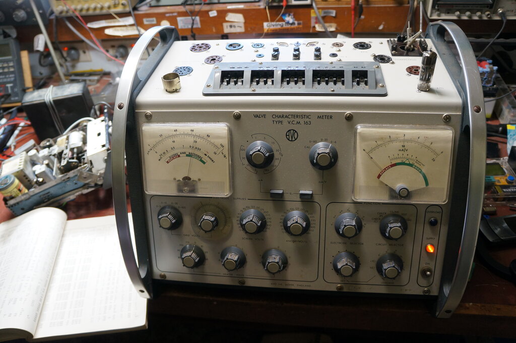
Testing the 6X4.
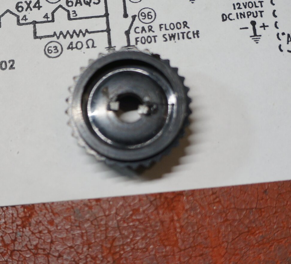
Knob repaired with new keys to engage control shaft slots.
After half a day's work it was successful. Anyway, the tone control is seldom used and there is little strain on it.
After running the radio all day as part
of the soak test, I had to disconnect the aerial to move the set to take
more photos of it. It was still switched on, and to my surprise, about
two minutes later, the background noise suddenly came up again. This was
the first time I'd seen the fault reverse itself after warm up. Applying
a signal again caused the volume to suddenly drop after a couple of seconds.
And, again, waiting a couple of minutes with the aerial disconnected, the
background noise came up again.
At last I could make the fault come and
go. This is always a significant turning point with diagnosing this kind
of fault.
First thing to do was put the CRO on the
IF amplifier plate. This showed a constant amplitude before and after the
fault occurred. That at least narrowed the fault down to between the second
IF transformer secondary and the audio output.
When using the external audio input fed
from an iPod, the fault was not evident at all. This further narrowed down
the fault to between the secondary of the second IF transformer and the
volume control.
I then started measuring the AVC voltage,
and also put the CRO onto the output of the detector, across C26. With
no fault, the AVC was -0.62V and there was about 50mVp-p of noise. When
the fault appeared, the AVC dropped to -0.58V, and the noise virtually
disappeared.
This was all done with no aerial connected,
since this was the only way to make the receiver work 'normally'. Touching
the aerial input with my finger was enough to make the fault appear.
Next, was to narrow down what stage of
the set the reduction in gain was happening in. With the grid of the 6BA6
IF amplifier shorted to earth, the AVC remained at -0.62V. It seemed we
had a situation where beyond a certain signal level after the 2nd IF transformer,
something was breaking down and clamping the audio and AVC voltage. This
tied in with the fault appearing only during warm up, since as the signal
increased as the set warmed up, it passed the voltage at which the fault
occurred.
At this point, it appeared the fault was
that something in detector circuit was breaking down at a certain voltage.
It wasn't the 6AV6 since I'd tried another. That leaves the two mica capacitors,
C26 and C27.
Mica capacitors have been shown to be
unreliable in the last 25 or so years, with intermittent breakdowns. In
this situation, the capacitors were always used where there was a reasonably
high DC voltage always across them. Such situations are plate bypasses
for audio amplifiers, and as coupling capacitors. The usual symptoms would
be intermittent scratching noises or changes in gain.
Could it be that the low voltage from
a detector was enough to cause a breakdown in mica capacitors?
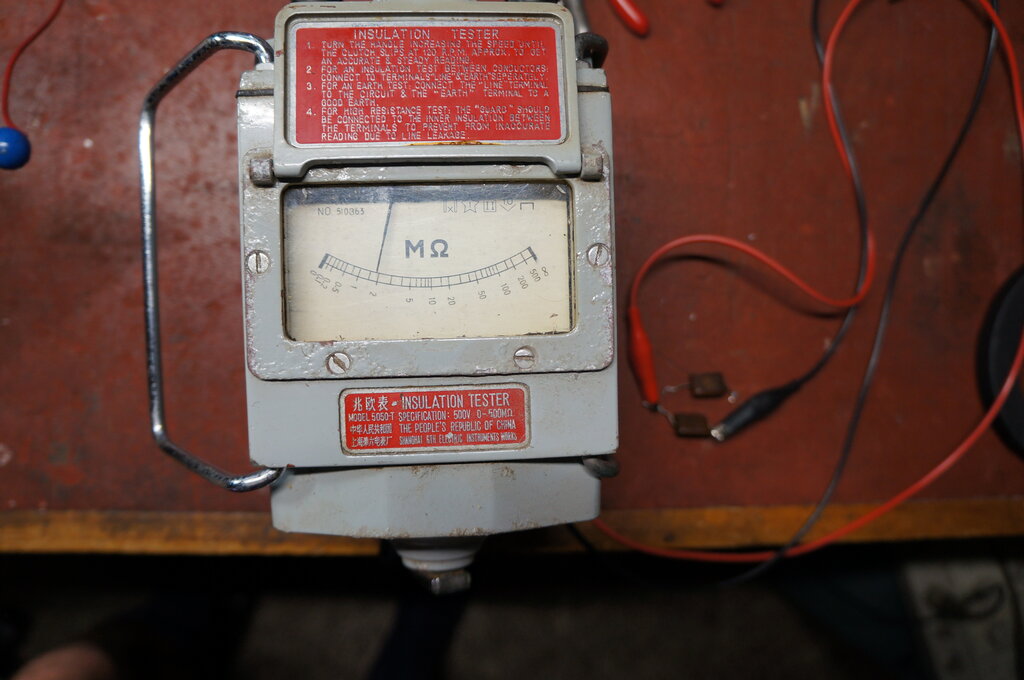
Mica Capacitor.
This is a first in my years of servicing
experience. Yes, one of the detector mica capacitors had failed. Measured
on the Megger tester, insulation resistance at 500V was down to 1M and
fluctuating.
The capacitor in question is C27 (100pF).
I replaced C26 as well.
No mica capacitors are beyond suspicion now.
With both capacitors replaced, not only did the radio just sound more alive with greater volume, but the AVC had risen from -4.9V to -7.2V. And most importantly, the fault was gone. At this stage of their life, it would be safe to say that any mica capacitor with DC across it is liable to fail. It is not voltage dependent as I previously thought.
One last fault!
While desoldering the mica capacitor from
the IF transformer, a piece of solder fell into the IF transformer adjustment
hole. I had forgotten about it and continued on using the radio. After
testing it outside the house, it suddenly stopped working, and the supply
current went up. Something shorted it would appear. It didn't take long
to narrow it down to the B+2 rail, and then I remembered the IF transformer.
It had to be removed from the chassis and opened to get the solder out.
Normal operation was then restored. The important thing to watch out for
when servicing radios with these IF transformers is not to let anything
fall into them. Not only will the object not come out simply by inverting
the chassis, but it will eventually lodge between one of the terminals
and the can.
Tuner and top of chassis cleaned up.
At my location on the eastern side of the
Blue Mountains, 2LT was received at good strength, when the radio was set
up in the backyard away from the RFI inside the house. This station is
about 60km away, but is directional with the signal away from my location.
The Sydney stations were received at good
strength. Performance was the same as the other Astor car radios I've restored.
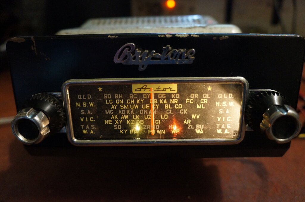
Note the two lights at the bottom of the dial. The white light shows
the tuner is in manual mode, while the red light is simply a power on indicator
- superfluous considering there is a dial lamp.
After the stresses and challenges of restoring this set, I did start to take a liking to it. Once it was back together with the last fault fixed, it became a nice set to use, and I enjoyed listening to it over the days of soak testing. Despite that, the Selectomatic tuner is a nightmare to work on, and its long term reliability remains to be seen. Service access to the control head is terrible. I'm familiar with the design now, but to a newcomer this would be a rather daunting set to service.
In this set, R57 is two paralleled 1W resistors.
I took the opportunity to replace R54
as well, even though it tested OK. This comprised three parallel 33k 1W
resistors of the same IRC type used for R57. I used a 10k 5W resistor to
replace it.
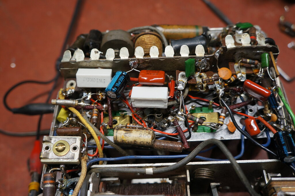
R57 and R54 replaced with 5W wirewound resistors.
There is 52V drop across the 1.5k resistor,
which results in 1.8W dissipation. It was getting a bit close to the full
rating of 2W, especially for old IRC carbon resistors. The use of a 5W
replacement will eliminate that problem in the future.
On a positive note, it was pleasing to
see it was almost two years before any fault developed, after the initial
restoration. Apart from the resistor replacement, nothing else needed attention
including the dreaded tuning unit.
The B+ voltage has not deteriorated, so
it seems the vibrator has remained in adjustment.