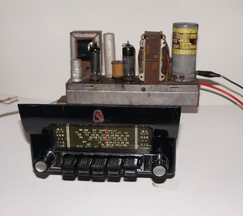
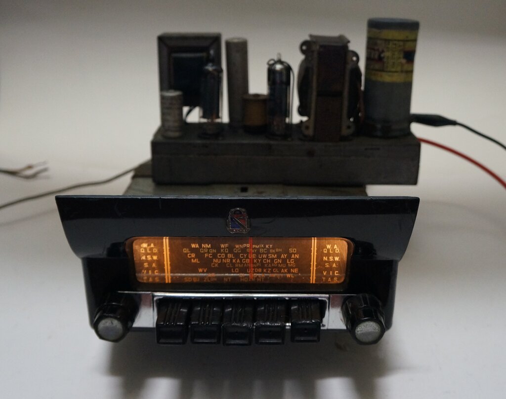
Astor ARM. Note the chassis mounted on top of the receiver. (Tuning knob borrowed for the photo).
Astor ARM. Note the chassis mounted on top of the receiver. (Tuning
knob borrowed for the photo).
This set came to me for restoration from
an owner of a 1957 FE Holden. If you had ordered the Nasco "Air Chief"
push button radio from your General Motors Holden's dealer, this is what
you got. Astor had the contract with Holden for their car radios, which
were branded Air Chief when supplied to GMH.
This particular radio had been purchased
from eBay as a "box of bits". It appeared that the radio had been pulled
apart with the intention of restoring it, but this had never been got around
to.
Looking at the photos in the ad, it looked
like all the parts were there, so I advised the owner to go ahead with
the purchase. Importantly, the plastic surround for the front was intact.
In more instances than not which I've seen, these have been broken.
I was already familiar with this model, since I have one in my collection (with a broken front surround). The ARM is 12 volts, and was also available in 6 volts as the ARL. Perhaps the most unusual feature with this model is the open chassis power supply, which is piggybacked onto the radio. Astor seemed to like this sort of "two unit screwed together as one" kind of design. The vulnerability of the exposed components could be a bit questionable. True, they're up under the dash, but mechanics aren't noted for being delicate, and should any work be required in this area, one has visions of broken valves, etc.
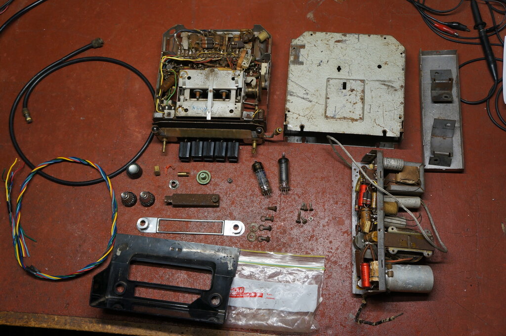
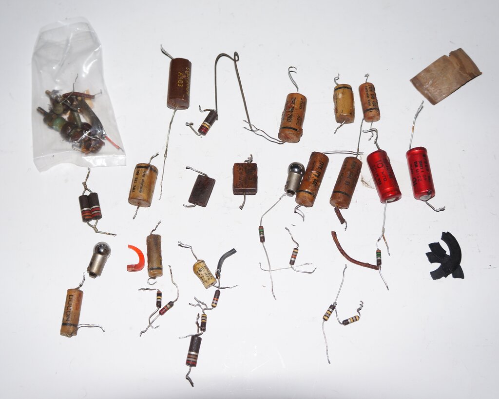
The contents of the box as purchased from eBay.
In due course the set arrived and I examined
the box of bits. It looked pretty good, but I did notice the knobs were
not the correct ones for this set. There were two chrome plated knobs supplied
which were obviously car radio types, but they were unsuitable for the
control shafts on this radio. There was also one of the correct knobs which
fitted the volume and tone control. I had ideas of modifying the chrome
knobs to fit. Not surprisingly, the plastic dial pointer was broken, and
some screws were missing.
The original cable between the two units
had been completely removed, and a length of wires which had been intended
as its replacement was in the box. Curiously, the 12X4 and 12AQ5 had been
removed from the power supply chassis. In the plastic bag containing screws
and other small parts was a 6X4 and 6AQ5. Not sure what was going on there
- perhaps the seller has misplaced the originals, but knew it needed a
*X4 and *AQ5, without actually checking the heater voltages. Or, as some
have been known to do, just supply any likely looking valves to make it
look complete for sale.
It was nice that the speaker and aerial
cables were also included.
Aside from that, it looked like the set
was well used, with a fair bit of cosmetic wear.
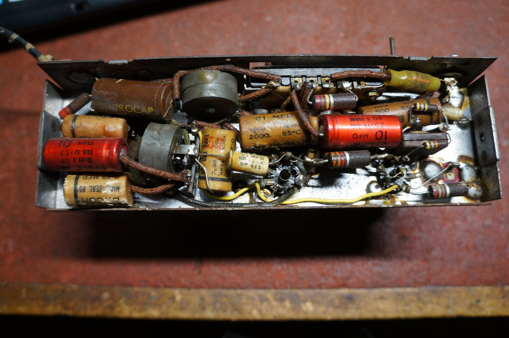
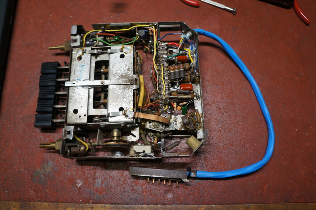
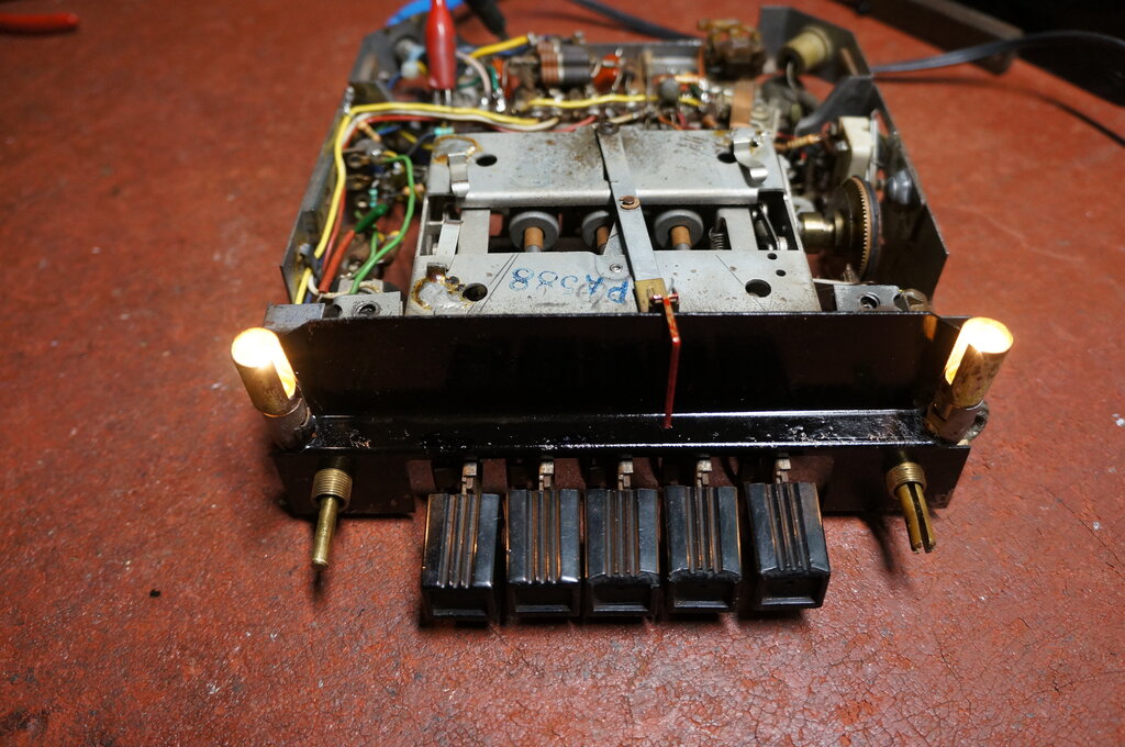
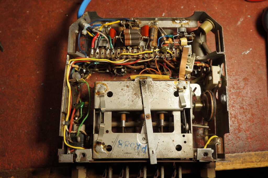
Power supply and output stage chassis.
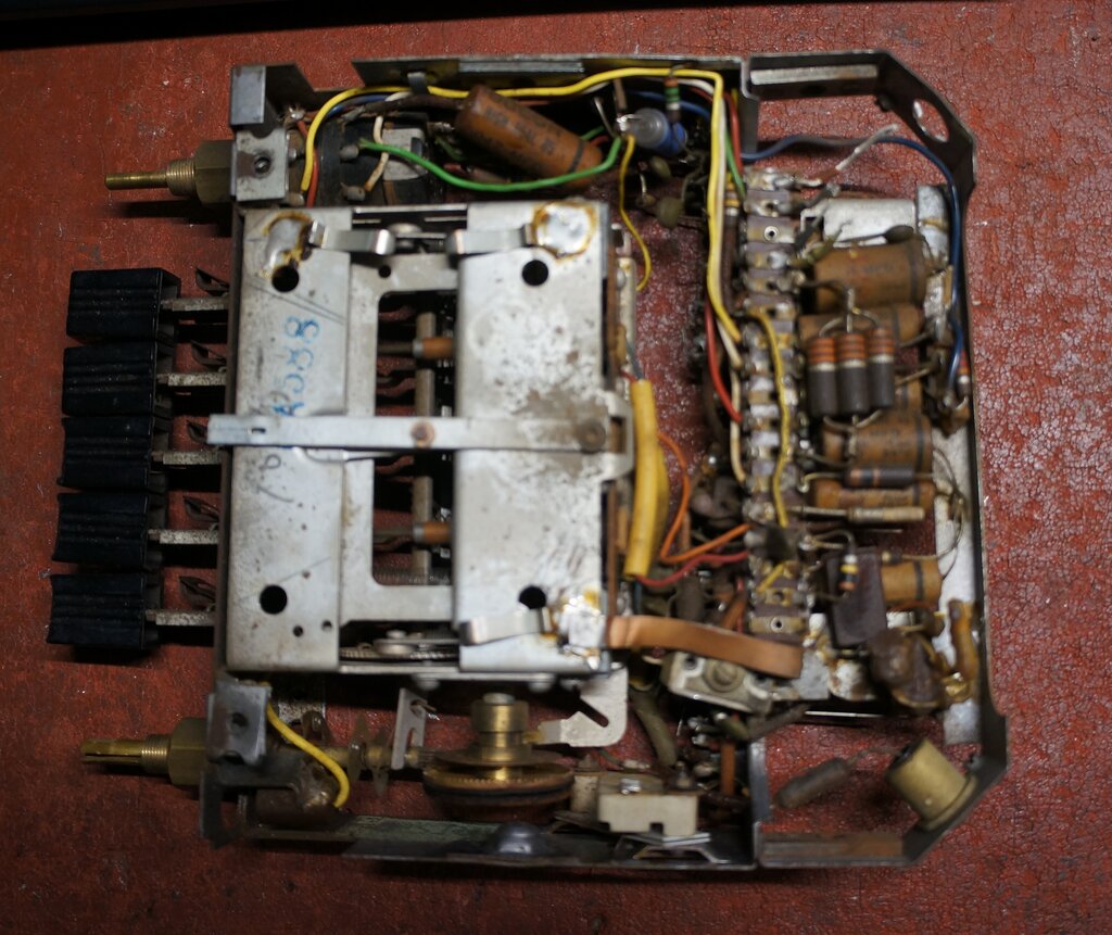
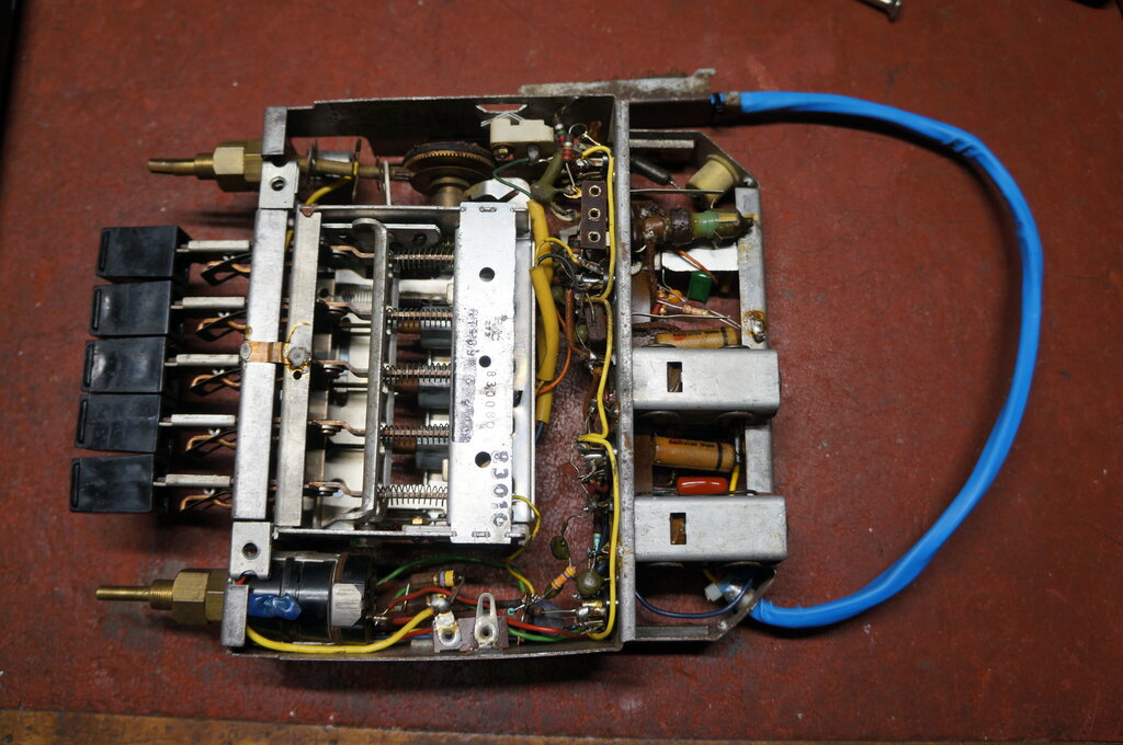
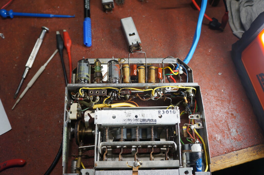
Receiver chassis. Valves and IF transformers are on the other side.
The Circuit.
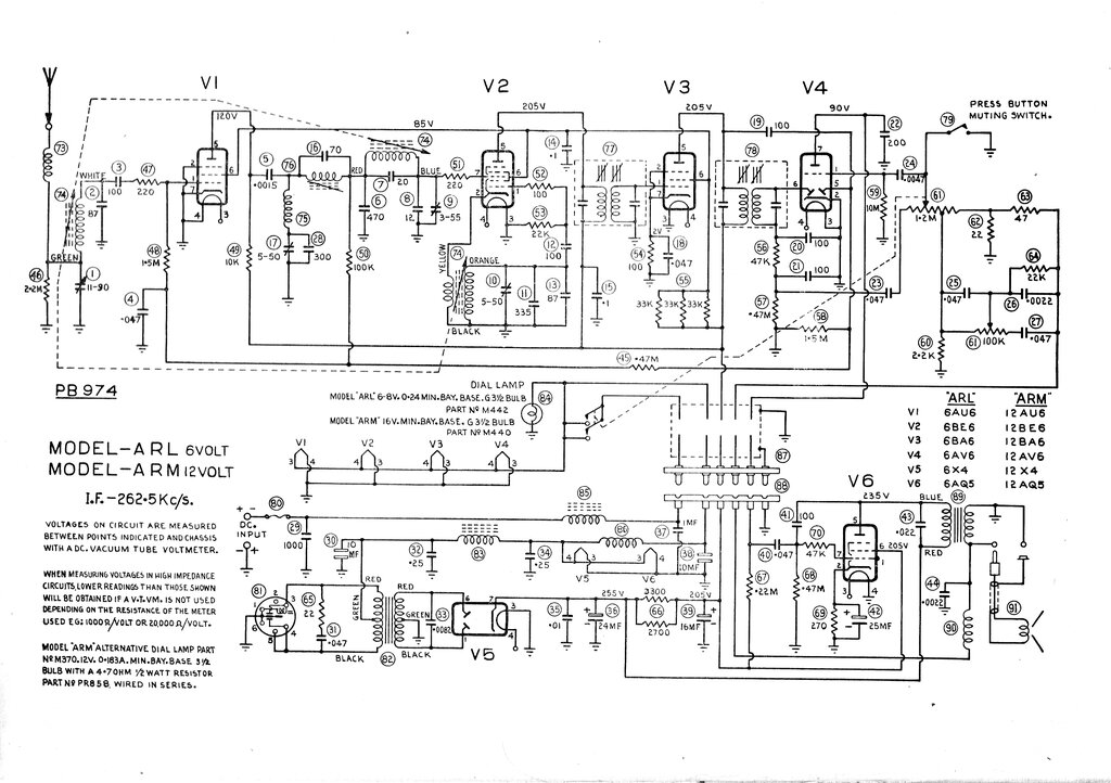
Note the IF is shown as 262.5Kc/s. This consfused a previous repairer
as will be explained further on.
The set is of conventional electrical design,
being a permeability tuned six valve superhet, similar to the RM and SS
sets which have been described previously. Points of note include the RF
stage with an untuned plate load consisting of a 10K resistor, but this
is common in car radio design. Also the AVC is not delayed. Again, we see
Astor's famed feedback circuit and tone control in the audio section.
The receiver connects to the power supply
and output chassis by a six pin plug and socket and a short length of cable.
The power supply is conventional with
a shunt drive vibrator. For the 12V ARM, this is a type PM238, and for
the 6V ARL, it's a type PM237. Of course, different vibrator transformers
are used depending on input voltage.
A difference compared to the preceding
models is that Astor are now using 12.6V heater valves for the 12V model,
rather than groups of two series 6.3V valves. This means the chassis wiring
is the same between 6V and 12V models.
Another point to note is there are two
electrolytic condensers on the 12V (or 6V) supply; C8 and C27. However,
these are non-polarised types, so the set can be used in negative or positive
earth cars with no modification. The vibrator of course, being non-synchronous,
is also happy with either polarity.
There are two versions of this set. One uses a 262.5Kc/s IF, and the other uses 455Kc/s. The one most commonly seen in the JR and AORSM manuals is the 455Kc/s version.
Capacitors.
First part of the restoration is of course
to replace most of the paper condensers, since all of them have some degree
of leakage by now. Despite being 'sealed' in wax, moisture still gets in.
And paper, being organic, is not exactly a stable dielectric. The paper
capacitors I left in the set were those associated with the audio feedback
circuit, since these are all shunted with low value resistors. Therefore,
any leakage which will be in the kilohm or megohm region will have no effect.
The condensers in question here are C42, 43 and 44.
Next, cathode bypasses can usually be
left in situ. In this set the IF amplifier cathode bypass C25, is across
a 100 ohm resistor. We can see the capacitor would have to be extremely
leaky to have any affect. Another thing to keep in mind is that the less
the voltage across the capacitor, the less the effect of the leakage.
Across the 12V supply are two paper capacitors,
C15 and C17. Again, at 12V, any leakage is harmless, since all that happens
is the current consumption of the set goes up by an immeasurable amount.
In a vibrator valve car radio are two
critical capacitors. First is the timing capacitor, C14, since anything
amiss here will ruin the vibrator. Secondly is the audio coupler, C32.
If this leaks, the audio output valve will draw excess current, damaging
it, and overloading the power supply.
During the capacitor replacement I noted that C14 had been replaced before. The circuit for this set, and various other Astor car radios shows the timing capacitor to be .0082uF. In this set it was .01uF. At first I assumed it was an Astor modification, but as I desoldered it, I noticed the leads were not wrapped around the valve socket pins. Evidently, the serviceman who replaced it didn't have the more obscure .0082uF, so used the more common 0.01uF. This is risky with a vibrator timing circuit, since change of value changes the timing of the voltage reversal when the vibrator contacts open. Too much capacitance also increases the peak current of the vibrator contacts. However, a few things made me decide to leave it at 0.01uF. First, I had already ordered a 0.01uF. Secondly, it's only one preferred value different, and thirdly, I knew I'd be adjusting the vibrator contacts, so could adjust them to suit the slight increase. It should also be pointed out that if a timing capacitor has to be replaced, and the exact value is not available, use the next higher value. Never go lower, since contact arcing and voltage stresses could occur. A higher value is less harmful, if one has to make a choice.
I also noted that C39 had also been replaced, since the original remains were still wrapped through the lugs and cut off. Apart from that all the resistors and capacitors were original.
Next on the list are mica condensers. These have become troublesome in the past 20 or so years, particularly where they are used in a high impedance circuits, and where DC is present across them. C37 is a common location for a mica which causes trouble. However, in this set a lot of the low value capacitors were ceramic, which reduced the amount of work, including C37. In fact, the only mica capacitors I replaced were C33 and C9.
Finally, there are the electrolytics. Australian made Ducon electrolytic capacitors are generally quite reliable, and I seldom replace them in any of my own sets. In this ARM they looked doubtful because of the way the set had been stored or used. If it was my set I would have kept them provided they formed OK and had low ESR, but it's foolish to take the risk, when the set will be in someone else's car, and not a good look if it fails. So, I replaced all three with new ones. For the two 10uF non-polarised electros on the 12V supply, I replaced them with new ones, but used ordinary polarised types since the set is only going to be used in a negative earthed car. They would have been OK to leave in terms of leakage, but I was concerned about an increase in ESR later on.
Resistors.
As always, the carbon resistors are suspect,
since these are the Australian made IRC type, which are notorious for drifting
high. It used to be just the high values, typically over 47K, but now I'm
finding even low value resistor in the tens of ohms are also drifting.
As expected, most of the higher value resistors were well out of tolerance,
but even the 270R cathode resistor (R68) was high and had to be replaced.
Similarly, the parallel 1W resistor combination, R58 was high. It was neater
and more convenient to replace this with a single 1.5K 5W resistor.
Cable.
This was originally a five conductor cable.
Connections it provides are: 1) 12V supply from battery, 2) switched supply
to power supply chassis, 3) B+ to front end of receiver, 4) speaker connection
to feedback circuit, 5) audio from 12AV6 plate, 6) earth.
The earth was originally the braid surrounding
the five conductors. I had ideas of reconstructing the cable using the
braid from coaxial cable, but it was just easier to do it how I did with
my own ARM. The only wire that really needs to be shielded is the one from
the 12AV6 plate, and for this I use RG-174 coaxial cable. The 12V and earth
wires are of sufficient gauge for the current, and the remaining two can
be light gauge for the B+ and speaker. The whole lot is then encased in
heatshrink tubing.
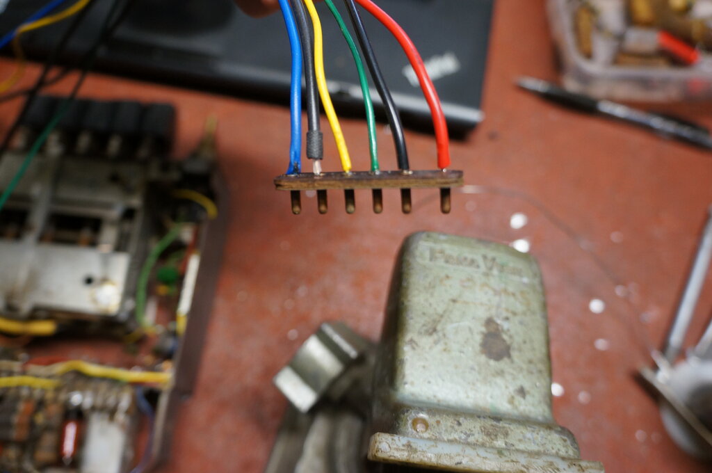
Six pin plug with new wires.
Completed cable covered in blue heatshrink tubing.
View from bottom of receiver chassis. Valves are not in the set
in this photo.
The 12V supply wire was also replaced since it had gone brittle and the insulation was questionable. The fuse holder was also missing, so this was replaced and a 5A fuse fitted.
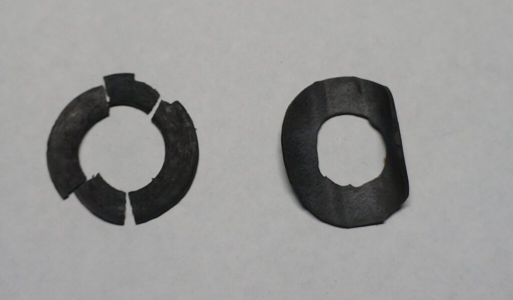
Original clutch lining on left. New one is at right. The straight
edge is an illusion from the curvature of the rubber.
Only one of the linings needed replacement. The new one was secured with contact cement. In order to get it over the shaft, a slot has to be cut in the rubber. Conveniently, the natural spring pressure keeps it all in place while the glue dries.
The dial backing plate was a bit faded, so it was resprayed in black enamel.
Faded and a bit grotty, this was an easy fix. Both dial lamps were
well used and burned out.
A new pointer was made up from a piece of brass and painted red.
New dial lamps and dial pointer.
Dial looking very nice lit up.
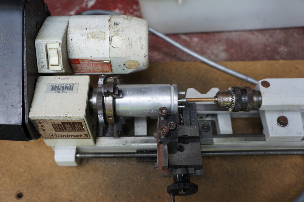
Vibrator in lathe ready for cutting the can open.
This did work - to an extent. Unfortunately the can got caught in the blade and got a bit damaged, but was able to straighten it out with my homemade vibrator can straightening tool. Also, some of the can material was lost due to the blade thickness. In retrospect, I think using a Dremel to cut away the aluminium folded over the base would have been better. Nevertheless, the vibrator was now opened up.
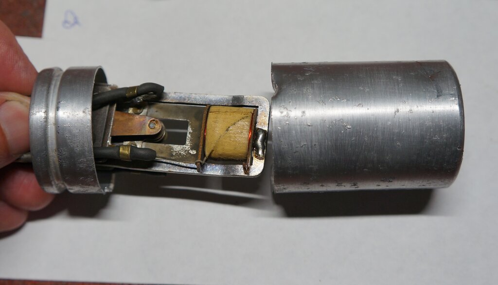
Can cut open. You can see where it got caught in the lathe. Note
the mechanism is tilted to one side.
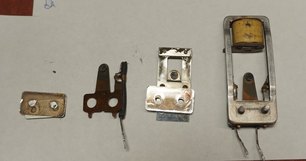
Vibrator disassembled.
This was yet another example of the lax
quality control of Ferrocart vibrator assembly. The pull contacts were
misaligned, with the reed contact hooking underneath where it had worn
into the fixed pull contact. Had the contacts been aligned correctly, the
wear would be even. It would obviously have to come apart, not just to
restore the contacts, but to reduce the spacing to improve the duty cycle.
As I've explained elsewhere, my preferred method for adjusting contact
spacing with Ferrocart vibrators is with the mica washers.
Apart from that, the mechanism had been
installed so the top corner was pressing against the foam rubber can insulation,
and in fact had worn into it. This is undesirable because the mechanism
needs to be able to float with no pressure on it. The operating characteristics
change when the mechanism is held rigidly, and it's possible this had something
to do with the unusually high rate of wear.
Unfortunately, the fixed pull contact was quite worn, and what I assume is monel metal (the part of the contact which the tungsten is bonded to) was becoming visible as I filed the contact. I could see it being unwise to return the radio with this vibrator fitted, since the tungsten layer was too thin and wear would be quite rapid.
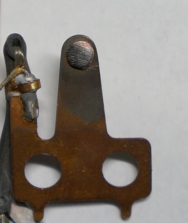
Note the tungsten has worn through at the top of the contact.
I do have some Ferrocart vibrator contacts from a vibrator with a broken reed, which I contemplated swapping over. But there was also the question of how to join together the aluminium can. In short, I decided I'd swap the vibrator with the one out of my own ARM, and rebuild that. Nevertheless, I did get the original going. The best I could get for the duty cycle was 70%, without actually bending the contacts. That was certainly good enough for testing, and actually worked well in view of the slightly larger timing capacitor. In fact, despite the wear, this vibrator was working very well with an excellent waveform. I decided this would become my 'test' vibrator for 12V Astor sets.
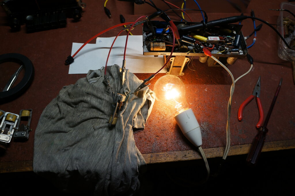
15W light bulb running off transformer secondary.
With no valves in the power supply chassis, a 240V 15W light bulb was used to test the vibrator under load. It was connected across one side of the transformer secondary.
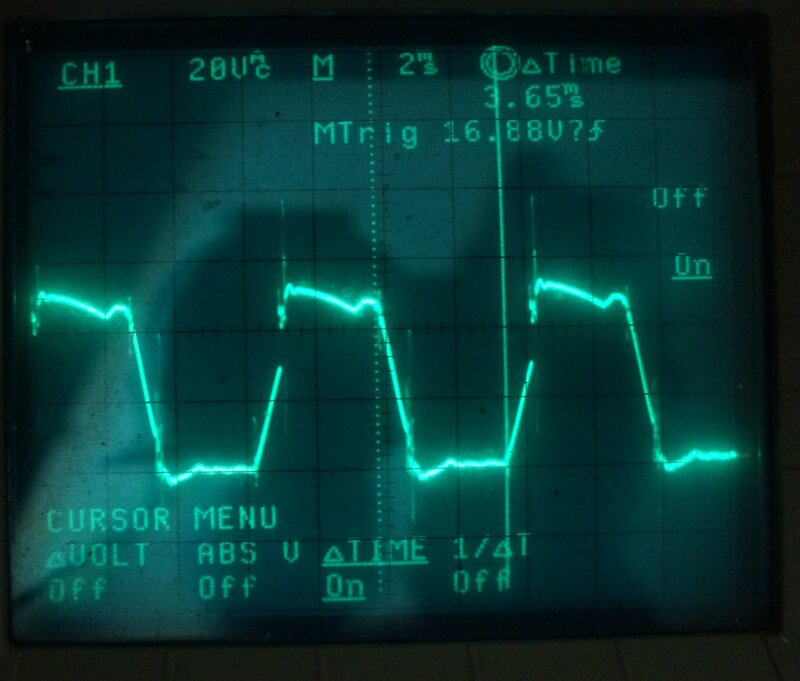
No load waveform was very good, despite the 70% duty cycle, and
suited the slightly higher timing condenser value.
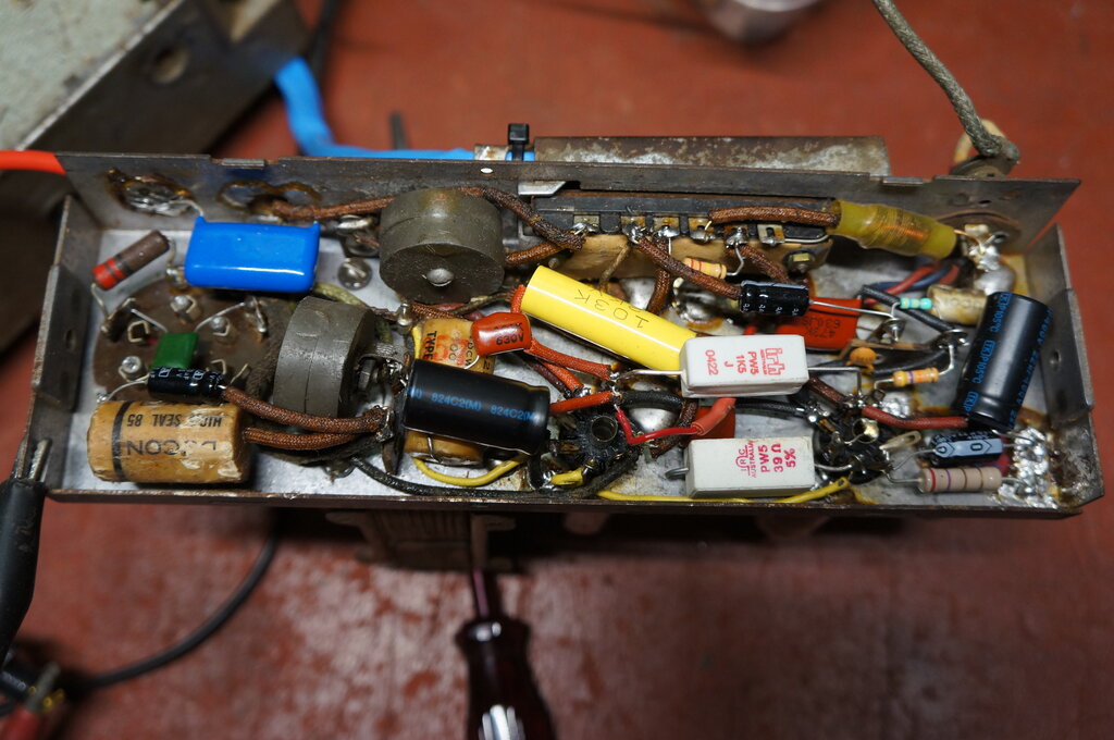
Note the 39R 5W shunt resistor. This allowed the supplied 6X4 and
6AQ5 to be used on 12V.
A point of interest is how critical is
this shunt resistor? It should be 42R, but is 39R going to damage
a valve? I did some calculations, and even with 39R, both valve heaters
are operating well within 5% tolerance; the 6X4 at 6.36V, and the 6AQ5
at 6.23V.
It must be remembered that neither the
6X4 or 6AQ5 were designed for series heater use. The stated heater currents
are only nominal. This means that the voltage across individual valves
of the same type might vary slightly, when fed with the same current. Incidentally,
there is a series heater version of the 6AQ5, which is the 6HG5. With the
two valves I had, fed from a 12.6V supply, the 6X4 received 6.17V, and
the 6AQ5 received 6.4V. If anything, 39R was still a little on the high
side.
Due to the chassis layout, rewiring the
heater connections was very easy, and there was ample room for the 5W shunt
resistor connected across the 6AQ5 socket.
Since this is a superhet, the position of the stations on the dial is entirely dependent on the local oscillator. They were all shifted up in frequency. The LO could only be running at too low of a frequency. There's not a lot which can cause this fault; possibly C16, 18, and 21, or the tuning coil, 79. Measuring the LO showed it to run from 782Kc/s to 1.88Mc/s, which was out of place. For a 455Kc/s IF, the LO should run from about 975 to 2073Kc/s.
Circuit Discrepancy.
And here I should mention a discrepancy
with the circuit, which I had noticed while replacing components. I had
up to this point used the 455Kc/s circuit diagram, since this was the only
one I was aware of. This is shown below for comparison:
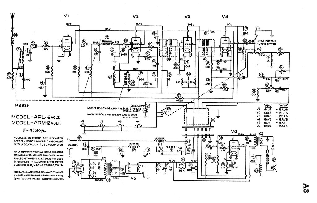
455Kc/s version of the set.
There was no coil 80 in this set. To obtain
oscillation, coil 79 was instead provided with a tapping. Also, C18 was
331pF instead of 50pF, and C21 was 87pF instead of 15pF. I assumed the
increase in shunt capacitance was due to the absence of coil 80, and the
modification of coil 79. Surely, the set must have worked correctly when
new, so the capacitor values must be OK.
I did test them, especially as C18 was
mica, but all were perfect. The local oscillator core didn't look in the
wrong position, compared with those of the RF and aerial sections. Besides,
it was locked reasonably tightly and wouldn't have shifted to that degree.
First thing I did was to make the LO to
run higher simply by removing C18 and C21, and substituting a 415pF variable
condenser. If I could at least make the set tune correctly, it might give
a clue to the fault. Unfortunately this idea didn't really work. Gain was
very low, despite it seeming to cover the correct frequency range.
Then, I tried adjusting the LO core to
'force' it on the right frequency with the original capacitor values. However,
the core was then in an absurd position, and the gain was still poor, presumably
because the tracking was off. It was not just a matter of misalignment.
As I've mentioned previously, I have my own ARM in working order. I measured its LO and surprisingly found it also to be 782Kc/s to 1.88Mc/s. Yet, it tuned across the band perfectly.
Then the penny dropped...
What if the IF was not 455Kc/s? After all,
262Kc/s has been used in car radios. A quick calculation confirmed that
what we had was two radios with a 262Kc/s IF. I had also noted two traps
in the RF circuit which were not on the circuit diagram, and presumably
these were related to the different IF.
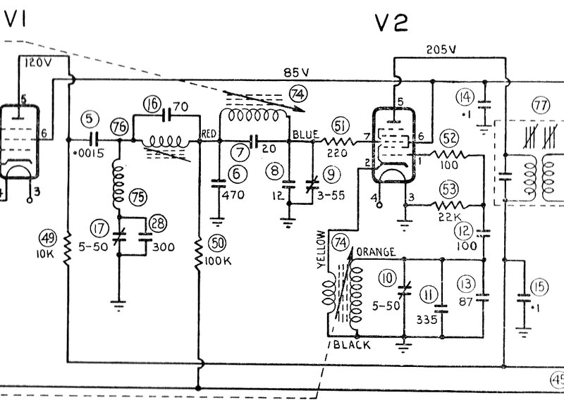
Circuit of front of the 262.5Kc/s version. Note the two trap circuits.
The 262.5Kc/s version of the ARM can't be too uncommon, since both sets I have encountered have used this IF. Yet, the circuits I had show only the 455Kc/s version. I discovered mention of a 262.5Kc/s IF version on the radiomuseum site, but there was no circuit. Interestingly, it mentions a 12AU6 as the RF amplifier. Later, I did obtain the complete service manuals for both versions.
My thoughts were that the last person to
work on the set assumed 455Kc/s, and tried aligning it to this frequency.
So, we just need to realign the IF to 262Kc/s, and the tuning will be correct.
Except when I did that, the gain was shockingly low. I thought about it
overnight, and remembered noticing the connections on the IF transformers
looked shiny, and I hadn't had to untwist any wires, when replacing parts
connected to their terminals. I was now beginning to suspect the IF transformers
had been replaced with 455Kc/s types.
Sure enough, they peaked very nicely at
455Kc/s. The false and weak 262Kc/s peak must have been a sub harmonic.
Looking at the IF transformers in my own
ARM showed they were indeed physically different, without the rectangular
cutout in the side of the can.
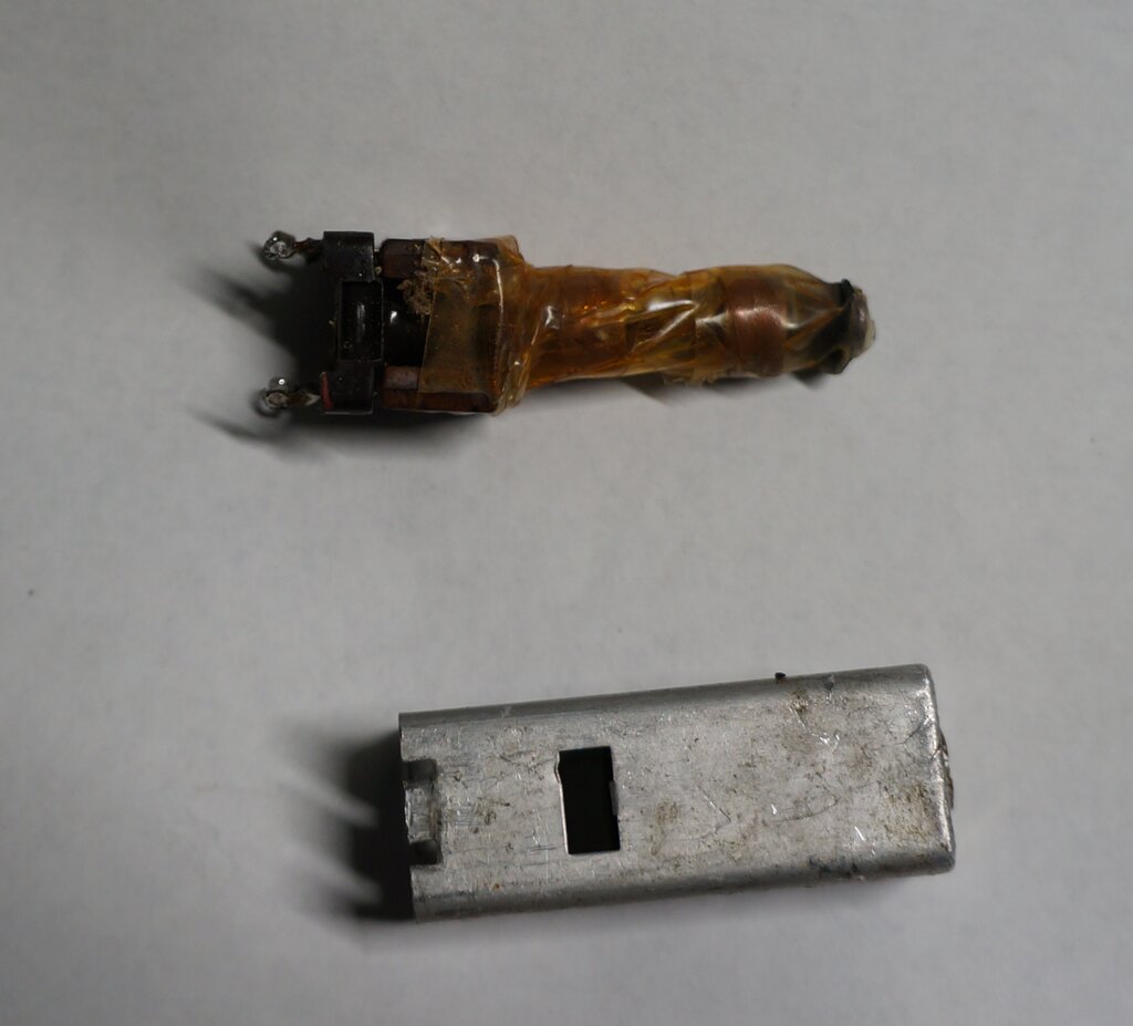
With such small windings, I couldn't see how these could operate
on 262Kc/s, even with the ferrite cups inside the cans.
Why would the transformers be replaced? Well, the circuit does show 455Kc/s, and if someone had attempted to do an alignment, they would have assumed the original IF transformers were faulty since they wouldn't peak. What they intended to do about the tracking error which resulted after fitting 455Kc/s IF transformers, I don't know. Maybe they weren't even aware of it, since the radio would still receive some stations in a reasonable signal area. Most people probably wouldn't even bother checking that the stations are in the right position on the dial, if the set seems alive enough to start with.
IF transformers removed for examination. The can design was different
to those in my own ARM.
Facing the Nightmare.
It was at this point I seriously considered
giving up car radio restorations for other people entirely. If the AWA
picnic portable caused me enough stress, look at what we have here.
Completely wrong IF transformers fitted, and the correct types are not
something on everyone's shelf. So what to do about it? Whatever happened,
some redesign was going to be called for. Choices are:
I had the remains of a Motorola car radio
with miniature IFT's. Maybe they were 262Kc/s, since this was common in
U.S. made car radios. Unfortunately, a quick test proved they were 455Kc/s.
Clearly, we were stuck with 455Kc/s, and had to make the set work with
that.
As I subsequently discovered, 262Kc/s
IFT's are not uncommon on the U.S. eBay, but by the time they got here
the cost would be at least $60, for the cheapest ones I found. In view
of the cost of this restoration already being bumped up by needing $127
worth of knobs, I really wanted to avoid going down this path.
Modifying tuner for 455Kc/s.
Permeability tuning is not my area of
expertise. I have never designed anything with it, and have never studied
its theoretical operation. Yes, we all know it's a variable inductance,
but the challenge comes with coupling the tuned circuits into the set circuitry,
and ensuring everything tracks properly. A look in the Radiotron Designers
Handbook taught me that for permeability tuning, we use a parallel inductance
to set the LO tracking, as opposed to a series capacitance in sets using
variable condenser tuning. This is what coil 80 is for.
Since there is no coil 80 in this actual
set, then coil 79 must instead be wound to provide correct tracking.
Simply reducing the capacitance as I had
previously tried would not provide correct tracking, hence the lack of
gain. Inductance was also needed. To illustrate why this is so:
In the original set the LO runs from 782
to 1880Kc/s. With about 433pF of shunt capacitance, this implies coil 79
has an inductance of 95.66uH to 16.55uH.
Now, when we change to 455Kc/s IF, the
local oscillator needs to tune from 975 to 2073Kc/s. Using the same coil
inductance range, with the set tuned to the low end of the band, the LO
is at 975Kc/s with the coil at 95.66uH. Capacitance needs to be 278.6pF.
At the high end of the band, with the
LO at 2073Kc/s and the coil at 16.55uH, the capacitance needs to be 356.2pF.
As you can see, there's no one value of capacitance which will provide
correct tracking across the band.
Padding Inductance.
Instead, it was necessary to use parallel
inductance to increase the LO frequency. This part of the redesign was
done entirely by trial and error. I do not profess to know the finer points
and theory behind it. Looking through all my Astor car radio circuits showed
that all of them used the separate padding coil (80). And all had a trimmer
capacitance (16). One would assume that the padding coil sets the tracking
at the lower end of the band, and the trimmer at the high end. Tracking
also tends to be a compromise and is not perfect right across the band.
There tend to be three points across the band where tracking is optimum;
at the low end of the band set by tuning coil inductance, the mid band
set by the padding circuit, and the high end set by the trimmer capacitors.
Certainly, in this set I didn't expect
perfect tracking, since the local oscillator coil was being called on to
do something it was never designed to. A logical starting point would be
mid band, since this is where the padding adjustment is normally set. I
used Sydney station 2UE on 954Kc/s.
Randomly selecting a 2.5mH RF choke and
connecting it across the LO coil increased the frequency slightly. For
the shunt capacitor, I used a 415pF tuning condenser. It was a simple matter
to find the optimum setting by adjusting this, along with the normal tuning
control to find where the signal was strongest. As it happened, the tracking
was surprisingly good, which was something of a relief, because it was
good enough to return the set this way if I had to.
I thought a variable inductance might be better than the fixed choke, and after looking around at what I had, it seemed that the now redundant 262Kc/s trap coil could be used. It was 4.3mH, but had enough adjustment to get it down to around 2.5mH. It did actually work fairly well, but the adjustment did nothing, since the minimum inductance was still too high. I didn't want to butcher it by removing turns.
Nevertheless, I wondered if less inductance
would be better. There was an improvement with a 1mH choke, and slightly
more so with 820uH. Tracking performance dropped off with 470uH. So, 820uH
it was to be. As for the optimum capacitance, that measured 358pF.
The obvious way to get 358pF would be
the existing 331pF with a trimmer. The existing trimmer, of the type using
a ceramic tube with wire wrapped around it, didn't have enough adjustment,
and was a pain anyway. I replaced it with a modern plastic film trimmer
of about 10 to 55pF. This, and the choke, were mounted on a tagstrip where
the old trap components were. The whole thing worked very well with consistent
gain over most of the band. The motorboating at the low end was gone.
RF choke and trimmer capacitor at top right next to aerial socket.
Unfortunately, when I put the dial together,
it was noticed that all stations were shifted higher. I had not taken into
account the greater arc of the tuning pointer, with it further from the
tuning mechanism. There is no adjustment for the dial pointer, so the three
cores would have to be adjusted instead. Firstly, with the pointer on 2UE,
the local oscillator core was adjusted for reception of this station. Then
the RF coil was peaked up, along with its trimmer C11, and finally the
aerial coil. It was nice to see that all three cores were much in line
with each other.
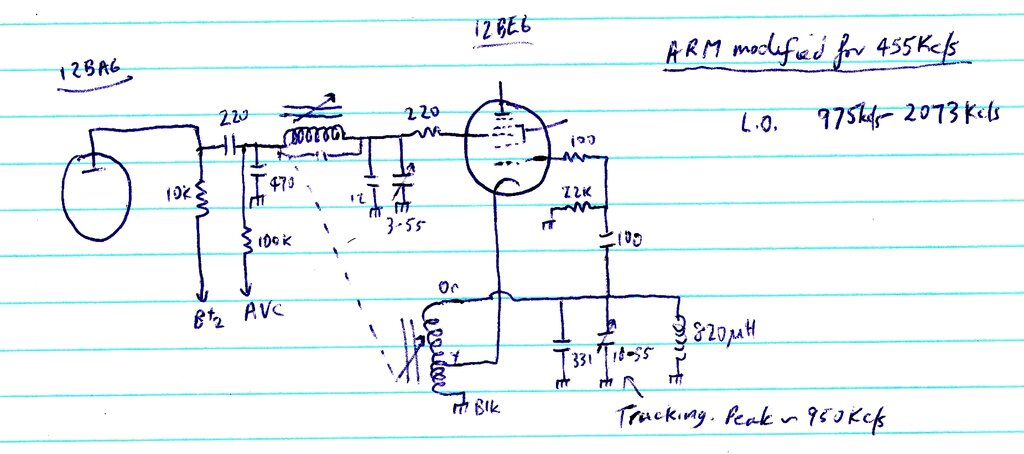
ARM modified for 455Kc/s with the 262Kc/s tuning unit. Padding circuit
added to oscillator coil, and 262Kc/s traps removed from RF amplifier.
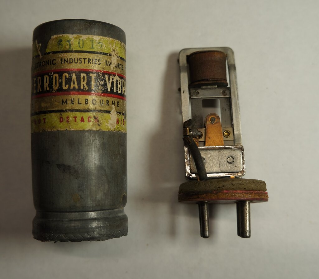
Restoring it was straightforward with the same contact cleaning and adjustment procedure as I've done with previous Ferrocart vibrators. The contacts were filed to remove most of the pitting, then polished with 600 grade sandpaper. The mica washers were adjusted to get 80% duty cycle. The rubber sleeving on the connecting wires had gone brittle so was replaced with cambric sleeving. Importantly, this vibrator also had the older zinc can which is easier to work with.
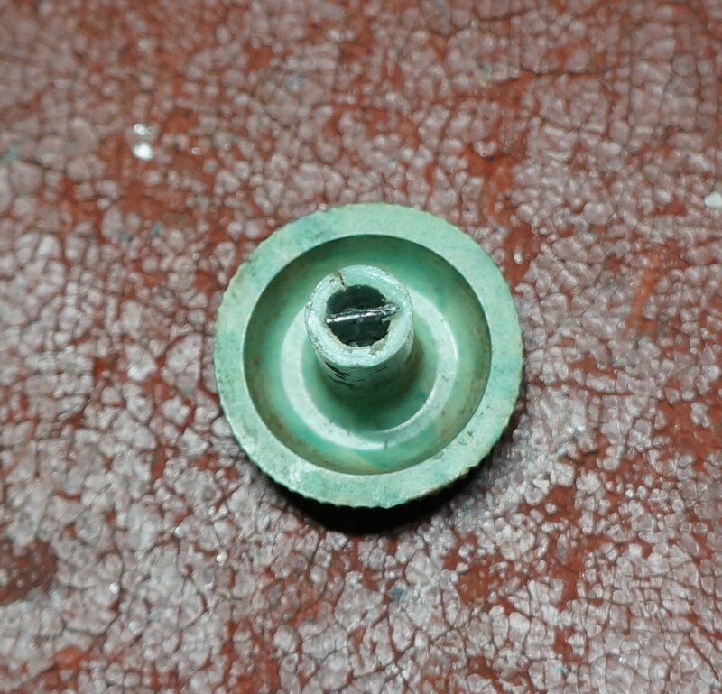
Piece of steel allows knob to grip trimmer capacitor shaft.
Final thing was to repair the aerial trimmer
knob. These are usually broken or missing, but one was included with this
set. Unfortunately it had been damaged, by someone forcing it beyond the
normal limit of rotation.
This had destroyed the two protrusions
inside the knob which engage the slot on the trimmer capacitor. It is an
easy repair, and I simply cut a piece of steel and pushed it into the knob
with a hot soldering iron. Being of a thermoplastic, the hot piece of steel
was easy to push into the knob, and becomes locked in place once it cools.
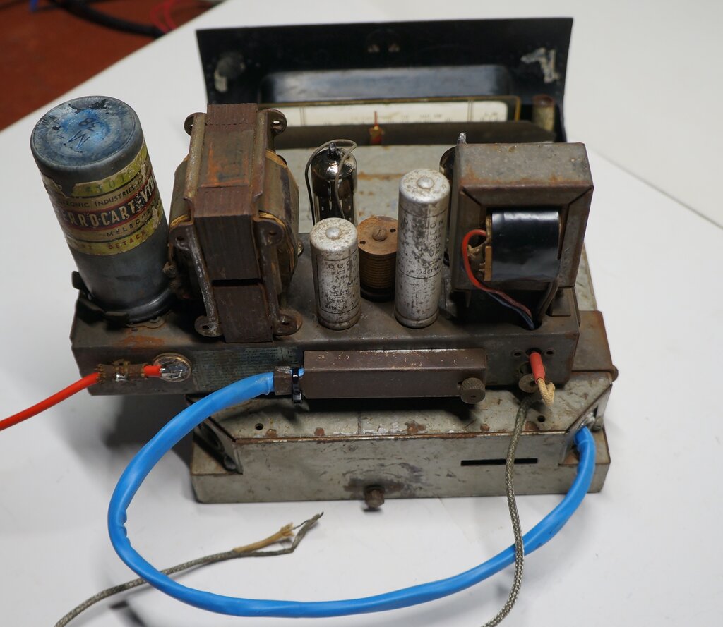
Power supply chassis is mounted on the receiver and connected with
a cable. Braided cable is for the speaker.
Parts replaced. The plastic bag contains the 262Kc/s trap components.
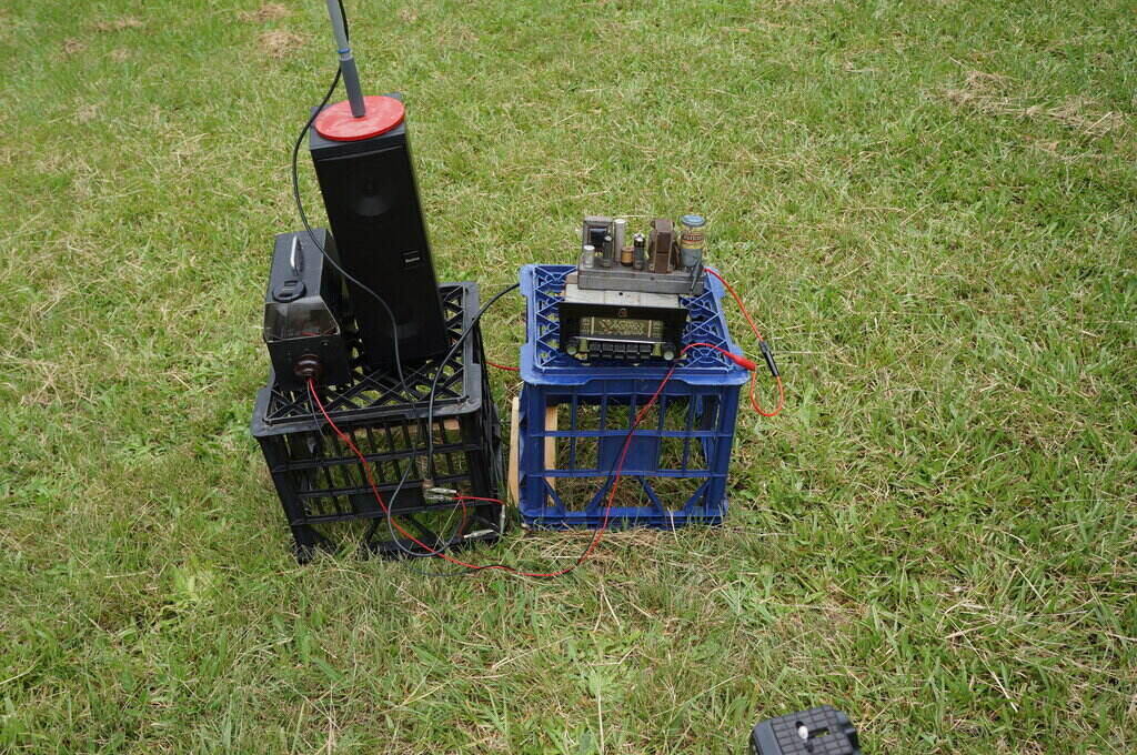
Outdoor testing of the ARM.
As usual, once the restoration is complete,
I do an off air test in the backyard away from all the interference in
the house. The results with this ARM really astonished me. The performance
was far better than I expected, and was surprised with how well 2LT (900Kc/s)
was received.
This station, as I've explained before,
is on the western side of the Blue Mountains, about 60km away from my location.
It is a directional transmitter with most power directed to the west. It
was received as well as the Sydney stations, and there were also a couple
of low power stations just below 2GB (873Kc/s) which I've not heard before
here. Given the horrors of modifying the tuning unit to work and track
with the 'new' 455Kc/s, I was really surprised how well it worked. Quite
a relief after all the worry and design work! Having said that, being expected
to perform miracles is not something I enjoy doing, although I have to
admit the results are satisfying when successful.