Generically known as a "Picnic Portable", this was AWA's portable car radio for 1963. The concept was to have a portable radio, which could be also used as a car radio by means of a cradle mounted in the dash, with a power amplifier and connection to the normal car aerial. Thus, one could arrive at the picnic spot, remove the radio from the car, and have it provide entertainment at the picnic table. This kind of set was produced by several Australian manufacturers during the 1960's. The set to be described is the AWA 982-A, made for the Ford Falcon. Different versions of this model were provided for different cars; each having different voltage and polarity requirements, different cradle shapes, and of course, different emblems for each brand of car they might be fitted to. The popularity of these sets was no doubt due to the high cost of transistor radios at the time. One could have both a portable and a car radio for the price of one. Car / portable sets actually go back to the Ferris 74 of 1947, and were popular in Australia more so than anywhere else. With the early Ferris sets, the "portable" designation inferred 240V mains operation in the home, but later a battery valve model was produced which was truly portable. These sets required the user to connect and disconnect the supply and aerial cables, and external speaker if used. And, the set had to be screwed to the in-car mount if this was used. Being able to simply slide the set into the dash and have all connections made automatically, as with this later AWA model is a considerable refinement.
It seems the 982-A model first appeared for the XL Falcon.
One of the 982-A sets came to me for repair from an early Falcon enthusiast who was also the owner of one of these AWA sets. This is the first time I have worked on a picnic portable, and it was a rather challenging experience to say the least! I had often wondered how well they worked, and what compromises there might be in the design.
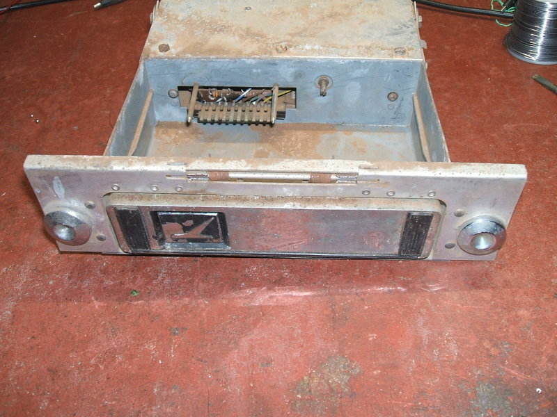
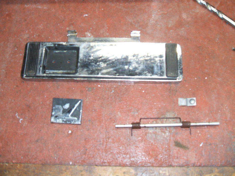
In dash mounted cradle. The two circular emblems at the sides mount
in the holes normally used for the controls of the standard radio.
The cradle itself is made of diecast alloy, and the power amplifier is mounted on the back of this in a simple aluminium enclosure. A spring loaded flap, also diecast, covers the cradle opening when the portable unit is removed. When the radio is inserted, two prongs cause a flap in the portable's base to open. This exposes an edge connector, which mates with contacts at the back of the cradle. Additionally, a third prong actuates a spring loaded slide switch inside the portable to change its operating conditions.
 \
\
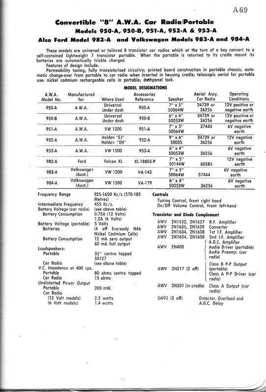
The set was made in several different versions.
When used as a portable, the set runs from
four NiCd cells. These are constantly trickle charged while ever the set
is in the cradle. As the portable unit is enclosed in a metal cabinet,
a ferrite loopstick aerial is impractical, so a small telescopic aerial
is fitted.
For cradle operation, the set is powered
entirely from the car electrical system.
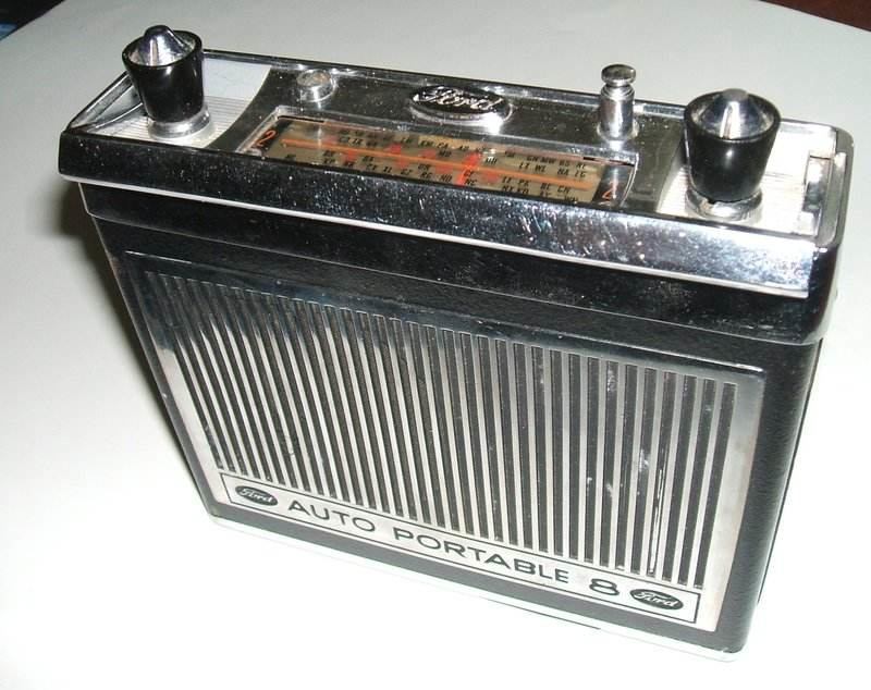
At first glance it looks like any other
seven transistor radio, but a closer look reveals two main differences.
A telescopic aerial is used for signal pickup instead of a ferrite rod,
and permeability tuning is used instead of variable capacitors. In fact,
the tuning unit is that of a car radio.
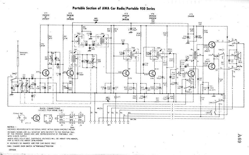
VT1 is the the RF amplifier operating
in grounded base mode. VT2 is an autodyne converter, the 455Kc/s output
of which passes through two IF transformers to the first IF amplifier,
VT3. Why two IF transformers are used is an interesting question, but the
way in which they are connected to each other suggests it's done to obtain
a specific response curve. The first and second IF amplifier are conventional,
and the demodulated audio comes from diode MR4. This feeds the class A
audio driver, VT5, via the volume control, which drives the two class B
output transistors, VT6 and VT7. These are thermally stabilised by thermistor
TH1 so that the transistor's bias is reduced with an increase in ambient
temperature. This is particularly important since the set will be used
inside a hot car during summer. Transistor failure will occur if they get
too hot.
As was common with AWA designs of the
era, a centre tapped voice coil in the loudspeaker removes the need for
an output transformer. Negative feedback operates on the driver stage only.
The radio operates from 4.8V, this being
obtained from four NiCd cells. A six section slider switch operates when
the radio is inserted into the cradle, and a 10 position edge connector
makes connection to the car aerial, power supply, and power amplifier in
the cradle. A dial lamp is included, but operates only when powered from
the car supply via the cradle.
AVC Circuit.
Where things start to get more unusual
is the AVC (Automatic Volume Control) circuit. AVC current is developed
from the detector diode, MR4, but is amplified by the first audio transistor,
VT5. There are two AVC circuits. One feeds the RF and both IF amplifiers,
and the other feeds the overload diode for the converter stage. In regards
to the first part of the AVC circuit, VT5 operates as an emitter follower.
This has current gain, but no voltage gain. Current gain is required here
because the method of AVC is to increase the emitter voltage of the controlled
stages. As the base voltage of each stage is fixed, raising the emitter
voltage reduces the bias current, and thus the gain. It can be seen that
the AVC circuit is of fairly low resistance, hence the current gain required
from VT5. MR2 is a delay diode. The AVC must increase to 250mV greater
than the emitter voltage of VT1, before the RF amplifier begins to be controlled.
This is standard practice with good receiver design, because it ensures
the converter is fed with the maximum possible signal on weak stations.
Overload diode, MR1, shunts TR2 under
conditions of very high signal strength. Again, VT5 comes into play, but
this time in its collector circuit. The voltage drop across R28, 470R,
depends on VT5's current, and as this voltage drop feeds MR1, it can be
seen that MR1 will conduct when R28's voltage drop exceeds around 250mV
(the forward bias voltage of a germanium diode).
Volume Control.
So how does VT5 also operate as an audio
stage, with a volume control, without affecting AVC operation? Looking
closely at the volume control pot, we can see the earthy end is actually
earthed only for AC (audio), by the 250uF, C34. Because of the pot being
only 2.5K, and the input resistance of VT5 being much higher than this,
the DC conditions of VT5 don't really change as the volume control is rotated;
only the AC component changes. Incidentally, this AC component does not
affect the AVC because of filters C32 and C35. In summary, the volume control
works as a normal voltage divider for the audio signal, and a simple series
resistor with minimal effect for the AVC.
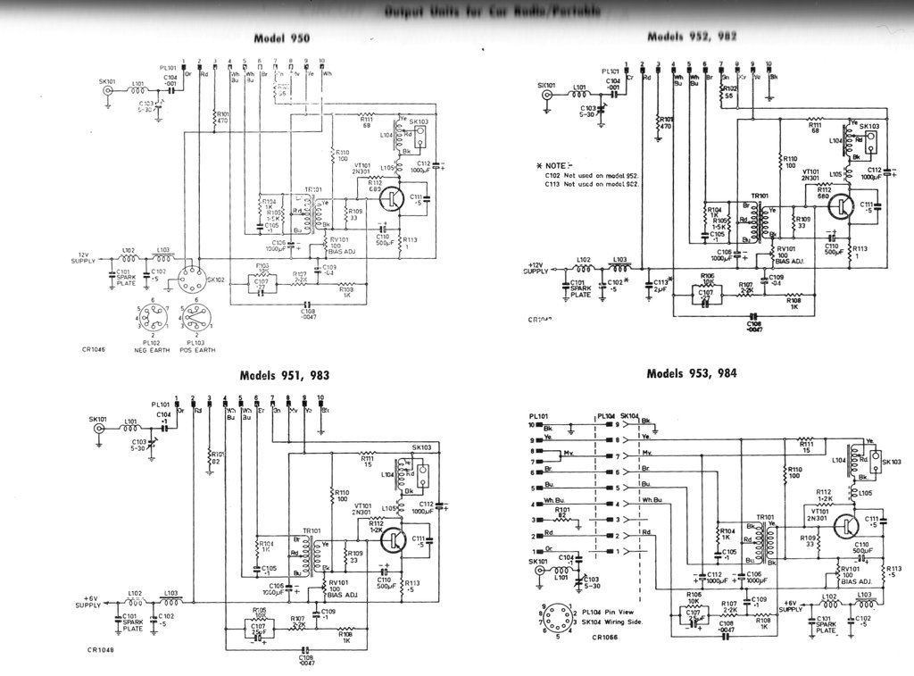
The circuit applicable to the set being described is for the 982
(top right).
Most of the cradle circuit is that of a
one transistor class A power amplifier, based around a 2N301 germanium
PNP transistor. The rest of the circuit is for filtering the 12V supply,
operating the portable unit (including the dial lamp), and charging the
NiCd cells.
The amplifier is transformer coupled from
the portable unit, and as such, the transformer TR101, has a centre
tapped primary to suit the push pull output in the portable. The secondary
of this drives the 2N301. Collector load is a tapped choke L104, which
feeds the 15 ohm speaker.
L105 reduces input of ignition interference
via the speaker wiring. The 2N301 has an adjustable bias control, RV101,
which sets the emitter current to 500mA. Stabilisation occurs via the 1R
emitter resistor. Loss of signal across this is prevented by C110. Some
localised negative feedback occurs by virtue of R112, but a more complex
feedback circuit also feeds the portable unit. This is the network between
the 2N301 base and pin 4 of the edge connector.
The dial lamp is a 6V type, and so the
56R 5W resistor, R102, is required to operate it from the 12V supply. The
radio circuit itself is fed from R111, into pin 9 of the edge connector.
The NiCd cells are charged from the 12V supply via the 470 ohm resistor,
R101. Charge current is around 15 to 20mA. Assuming the NiCd cells have
a 500mAh capacity, this is not high enough to cause damage when fully charged.
The cradle must be connected to the car battery at all times. This is against
the convention of using the accessories circuit. The reason for this is
that the NiCd cells would take an unacceptably long time to charge, if
charging current was only applied when the car was driven. Furthermore,
the cells would discharge into anything connected to the accessories circuit
when not in use, through the 470R charging resistor. It is true that simply
connecting a diode in series with the 470R would avoid this. To charge
the cells at the full rate (C/10) would risk overcharging them on a long
drive - hence the trickle rate.
An aerial socket is provided on the cradle, with aerial trimmer; this being required because of the different capacitance of the portable's telescopic aerial to that of the car aerial. This feeds the RF input of the portable via pin 1 of the connector.
1) The internal telescopic aerial is disconnected,
and the car aerial fed into the RF input circuit.
2) The +12V car supply connects to the
earth rail of the radio. Note the use of PNP transistors requiring a negative
supply rail.
3) SWA/4 disconnects the NiCd cells from
the radio and connects them to the 12V car supply via R101 (470R) at pin
3 for trickle charging.
4) Pin 4 connects the negative feedback
circuit of the power amplifier into the emitter of VT5. Gain of VT5 is
reduced by switching in R27 (47R) via SWA/3.
5) The collector of VT6 is disconnected
from the internal speaker by SWA/5 and connects to one side of the power
amplifier driver transformer TR101 via pin 5.
6) The collector of VT7 is disconnected
from the internal speaker by SWA/5 and connects to the other side of the
power amplifier driver transformer TR101 via pin 6.
7) The 6V dial lamp is fed from the 12V
car supply by dropping resistor R102 (56R).
8) Pin 8 switches the 12V car supply to
feed the cradle circuit via the switch on the volume control, one pole
of SWB. Input is pin 10.
9) Pin 9 feeds the supply rail of the
portable. It comes from the 12V car supply via dropping resistor R111 (68R).
10) Pin 10 is the negative 12V input into
the switch SWB on the volume control. The switched supply comes out at
pin 8.
R34 is now connected in series with VT6 and VT7 emitters by SWA/2 to reduce their gain and provide better temperature stabilisation with the slightly higher supply voltage. To offset the decrease in base bias which occurs from this, R31, (1K), provides extra current into the bias circuit. It's fed from -12V.
Because of the use of PNP transistors with a negative earth car electrical system, it means the "earth" inside the portable has to be floating with respect to the car chassis. This earth rail is bypassed for RF to the chassis via C7 (0.1uF).
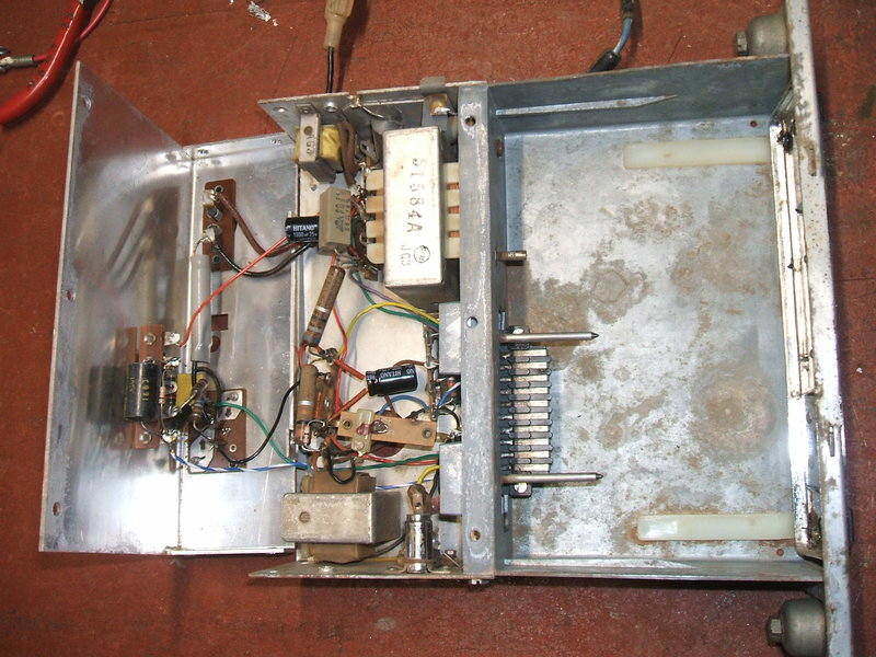
Inside the cradle after capacitor replacement.
The Portable Unit.
This involved replacing all the electrolytic
capacitors since they were the unreliable blue Philips types. The only
paper capacitor was also replaced. Accessing the PCB seemed tricky at first,
but once I discovered the secret, it was quite easy to service. Once the
chassis is slid out of the case (two countersunk screws at the bottom),
it is necessary to remove the front panel, by removing the knobs and then
the threaded bushings behind them. After that, the three small self tappers
securing the speaker panel are removed. Pretty much all components can
be now accessed.
After an evening replacing capacitors,
I was pleased that feeding 5V into the battery terminals produced results.
Alas, the volume control wasn't working very well, with full volume until
the pot was rotated about half way, upon which the sound dropped out altogether.
I just assumed a drop of switch cleaner on the carbon track would fix it,
and would deal with it later. Sensitivity seemed poor and the dial calibrations
were out. Adjusting all the trimmer capacitors with a signal at 1500Kc/s
fixed that.
Component side visible.
Next, was what do about the NiCd cells.
There were none with the set, and if there were originals, they would be
doubtful anyway. The battery holder is labelled with "Eveready N46". I
had not heard of this number, but from the size of the battery holder,
it looked like they were AA size. It turned out this was not quite so.
Normal AA cells of NiCd or alkaline were slightly too wide of diameter
to fit. Looking up N46 showed it was a 1960's designation, and nothing
modern existed under that number. I toyed around with the idea of using
AAA cells surrounded by heatshrink tubing to build up the diameter. Before
I reached for the WES catalog to see if there were any modern NiCd cells
of suitable size, I had a look through my own collection.
The battery holder is made out of a stiff
but thin black plastic, moulded to the contour of the cells. The cells
are inserted into it, and then this is retained in the radio secured by
a 4BA screw at the radio base. However, one side of the battery holder
had a white tube attached to the inside. It would appear this was to function
as an insulator to stop the cases of the adjacent cells touching.
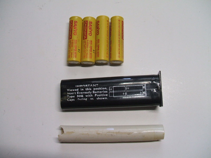
Sanyo NiCd's fit provided the white tube is removed from the battery
holder.
What I discovered is that Sanyo N-600AA
NiCd's fitted the side of the battery holder without the white tube. Removing
the white tube allowed all four cells to fit perfectly. I charged them
and reassembled the radio. Taking it outside, it seemed to work well away
from the interference in my workshop. But, the volume control problem was
still there. The radio had to be disassembled again (this was going to
be the first of many times!), and a squirt of CRC was applied to the carbon
track. Unfortunately, there was no improvement.
At this stage the control had to be removed
for testing - and there it was - not something I wanted to see. The carbon
track appeared to be open circuit part way along the track. There was nothing
to do now except dismantle the control and see what the fault was.
I could clearly see there was just no
carbon on part of the track. Why it was like this is curious because wear
from the wiper will just wear a narrow part of the track. However, there
was no carbon either side of where the wiper makes contact.
One thing that concerned me was
the tiny switch contacts; they look inadequately rated for the current
used by the entire set.
I spent an afternoon trying to see if anything at all was on the internet. Well, CTS, the company that made it, still exists. But there was no "Type N" to be seen anywhere. There was the option of having them make one to special order, but that would be horrendously expensive, and presumably, a minimum order would be required. Furthermore, the only switches available were single pole. One could no doubt come up with a way to use a single pole switch for the 12V supply as well as the NiCd's, but I'd prefer to avoid the modifications that would entail.
Repairing the carbon track didn't seem to be an option. Where would one get carbon paint of suitable resistance, and how well would it wear? The old trick of pencil "lead" (actually graphite) to repair potentiometers is well known, but has poor wear characteristics.
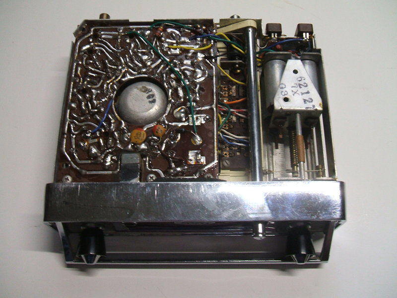
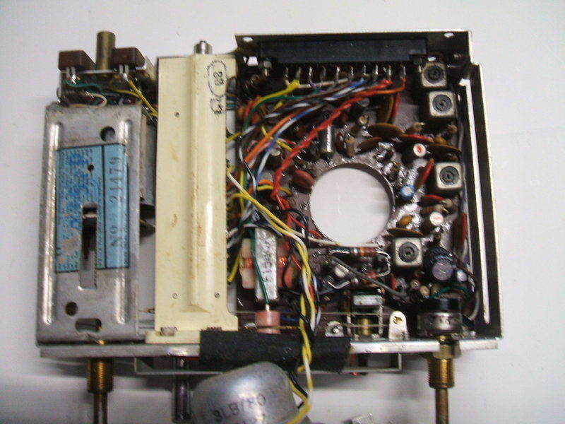
Track side of PCB. Permeability tuning unit is to the right. Slide
switch can be seen adjacent to the telescopic aerial.
Carbon Track Transplant.
What about replacing the carbon track
itself? If I had another pot the same size, the carbon track and its terminals
could be swapped over. I mentioned the problem to the owner. He enthusiastically
suggested I get the volume control out of another identical set he happened
to have. And so, the other set duly arrived and I tested its pot - about
4K which was higher than the specified 2.5K. This would not be a problem
as the value of a volume control resistance is not critical in this type
of circuit. Importantly, the track was continuous. Having transplanted
the pot, I tested the set again.
It was a lot better, but two problems
existed. It was impossible to reduce the volume to a complete minimum before
the switch was in the "off" position. Also, with the switch "off" the radio
continued to play. The set of switch contacts for the NiCd's was not opening.
In the cradle it was much worse. The added
gain of the cradle's power amplifier made this "minimum volume effect"
(I'll call it MVE - because it will be referred to a lot more), much worse.
It was such that with the volume in the minimum position, the sound was
at a level that would suit ordinary driving conditions. It could not be
reduced except by switching off the set. As a portable, with the lower
output and smaller speaker it wasn't quite as bad.
Evidently, the resistance of the carbon
track was just not low enough at the earthy end. With the second control
in a row faulty, I can only conclude there is a manufacturing fault, and
do not hold any optimism for easy restoration of these sets.
Back to square one!
I had a look though my miniature pots to see if any had a carbon track of suitable size. Nothing was exact, and the wiper arrangement wouldn't be compatible anyway. What about mounting a miniature trimpot inside the body of the old pot? This is where there was a light on the horizon - finally! It just so happened I had three medium size trimpots made by CTS. It turned out the carbon tracks were identical in size. However, the phenolic disc on which the carbon track and terminals is mounted was not compatible with the switch pot. Anyway, I selected a 40K pot. The other two were 1K. I figured a higher resistance would be better than a much lower one. It would be easier to fudge operating conditions to make the circuit "see" a lower resistance if necessary.
For the first time I was going to try transplanting an actual carbon track. It is held to the phenolic disc by two crimped terminals. By gently unfolding the tabs of these, they lifted off, and the carbon track was now free. All I had to do was do the same with the switch pot and put the good track in it, re-crimping the terminals. Pleasingly, it all went together without problems, and a resistance test indicated all was well.
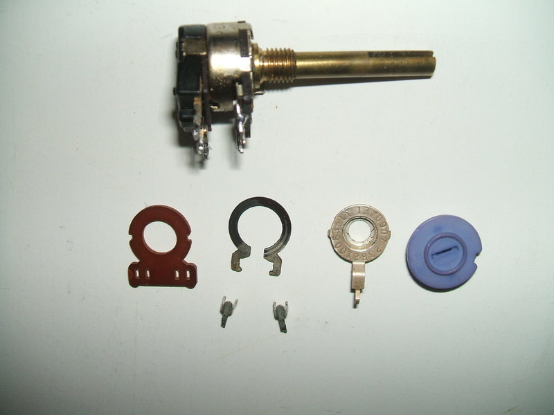
Volume pot above. Below is the dismantled CTS trim pot. The carbon
track is the defective one. No carbon is present between the 12 and 2 o'clock
part of the track.
After putting it back in the set, it was a huge improvement. In fact, I considered it fixed at last. More testing indicated this wasn't quite so. There was now a noticeable time delay before the AVC had effect. Tuning into a strong station (2BL and 2FC in my area), would result in distortion for about half a second before the AVC could reduce the gain. The cause was obvious; now with 40K of resistance, it took a lot more time for C34 to adjust its charge than when the resistance was 2.5K. This was easily fixed by reducing the capacitance to 22uF. With 40K in series, this was still sufficient to bypass all the audio at the earthy end of the pot. As a portable, it was now working really well, and I was pleased to have overcome something which seemed impossible at first.
The Minimum Volume Effect.
Sadly, back in the cradle we were back
to the dreaded MVE. It was a lot better than previously, but would be annoying
in some situations. So what was causing it? To explain this, we need to
think about how a switch pot differs from an ordinary pot. With a normal
pot, the wiper can traverse the carbon track from end to end. At each end,
the resistance will be zero ohms. However, with a switch pot, the wiper
does not reach the earthy end until the switch is off. That is, with the
set switched on, and the volume low as possible, the wiper is actually
a few degrees of travel along the track. Thus, it is above the zero ohm
point. A carbon track for a switch pot therefore needs to have a longer
section of "zero ohms". The track I put in of course was the normal type,
and in the minimum volume position was about 143 ohms. This seems low enough
when one considers the rest of the track is much higher at 40K. And indeed,
used in the set as a portable, the minimum was quite acceptable. But there
was nevertheless some signal getting through.
How to make it acceptable for cradle use?
First thing I tried was to reduce the gain of the power amplifier by increasing
the negative feedback. A 2.2K resistor across C106 gave as much feedback
as I could get away with, before it oscillated. This helped, but on strong
stations with the car parked with the engine off, it could still be annoying.
Another idea came into my head - what if we reduce the signal by retracting
the aerial? Yes, that did help, and could be used as last resort, but the
problem was background hiss because of the set operating at full RF/IF
gain.
Next thing to try was reducing the gain
of the power amplifier another way. First attempt involved removing C110,
so that full feedback would occur across the 1R emitter resistor. This
was looking good with a noticeable reduction in the MVE. With the aerial
retracted it was even better.
At this point, I rang the owner to explain
the situation and was preparing to finish up the repair and send it back.
I couldn't quite let go of it though. It was an expensive repair, and I just wasn't happy about returning it with the annoying MVE, and having to adjust the aerial length to reduce it. So, I persevered some more. As I discovered, removing the emitter bypass capacitor was actually not the best thing to do - the output power was reduced to about 880mW instead of 2.5W. Fine for a quiet workshop, but not inside a running car. I then tried a resistor in series with the driver transformer secondary. Surprisingly, this didn't have as much effect as I hoped. The output stage in the portable unit would go into overload before full power output from the 2N301 could be obtained. That killed off that idea.
It seemed we had to remove the MVE in the portable, rather than throttling it back in the cradle unit.
Opening the portable for the umpteenth time, I had another idea. There was an unused switch contact on SWA/2 which made connection to earth when the set was in the cradle. What if this was used to shunt the wiper of the pot to earth through a resistor (and series capacitor so as not to disturb the DC)? The volume would be reduced only when the set was in the cradle. Good idea, but alas completely unsuccessful. The value of resistor required was too low to allow full volume, when the pot was rotated full on. I tried a shunt resistor in similar vain, from the wiper to the earthy end of the track, again without success.
Modifying the AVC.
It had now become clear that the audio
would have to be reduced before it even got to the volume pot, but at the
same time allow for full volume. This is when I had ideas of using the
pot to do something DC-wise to shut the thing up with the wiper in minimum
position. Ideas of a shunt transistor or diode to short out or heavily
bypass the audio entered my mind. But then, I realised a simpler way -
use the AVC circuit instead. Somehow reduce the RF/IF gain with the volume
control in minimum position.
Breakthrough at last!
It was all so elegantly simple in the
end. I had noted that taking the earthy end of the pot slightly negative
(towards the supply rail), forced the AVC to reduce the volume completely.
My theory was, if a permanent bias was put on this terminal, the radio
would be silenced with the wiper at the earthy end. As the volume was turned
up, the normal AVC would take over, being isolated by 40K of resistance
at max volume. A 150K resistor to the negative 4.8V supply did the trick
and the idea worked like a charm. There was no loss of output power or
sensitivity. Indeed, the set was happily receiving 2QN in the afternoon.
What I had done was simply to shift the operating point of the volume control.
Importantly, in the cradle, the MVE was more than acceptable. It could
actually be reduced even further by reducing the 150K if need be.
The question I have to ask is, what were
these sets like when new? The slightest bit of resistance at the earthy
end of the volume pot causes an unpleasant MVE when used in the cradle.
To finally tidy up things in the electrical
sense, I had noticed the 2N301 bias was a little high. The 100R bias adjusting
resistor is really too high with only a small section used. I simply paralleled
a 39R resistor across it, which brought the collector current down to about
500mA. I also replaced the previously mentioned 33R resistor with 10K as
per the circuit (R106). They wouldn't have noticed the mistake when the
set was tested at the factory, but replacing this resistor did give a small
amount of low volume bass boost.
Cosmetic Stuff.
The owner had noted the chrome was in
poor condition on the cradle flap, but that of the donor set was excellent.
He requested I swap them over. This was easy to do by drilling out a rivet
to extract the flap and spring. The flaps have emblems; the donor was AWA,
and the original was Ford. The donor set was actually a 952-A, for an EH
or EJ Holden. It was labelled as "Convertible 8"
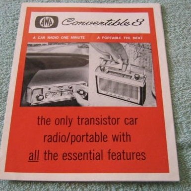
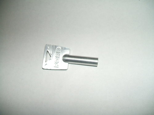
Advertisement for the generic version. At right is the key used
to lock the portable into the cradle.
The flap emblems are of the same diecast material as the flap. They're held in by studs which are easily drilled out. I used contact cement to secure the Ford emblem on the new flap. Something noticed throughout restoration was the battery holder screw only went in a few turns. The screw was found to be a 4BA size, and so a tap was run through the hole. This fixed that minor problem, allowing the battery holder to be fully inserted. Diecast metal is known for swelling up, so the tight thread was not surprising. I noticed the same with the donor radio.
Cradle flap dismantled. Note the Ford emblem.
The donor radio was reassembled as it was not required to be repaired. It was missing the battery holder and dial scale. I did experiment with reproducing a dial scale by scanning the one on the Ford portable, and printing it on a transparency in a colour laser printer. The concept worked fairly well, except it came out a little too small. As I wasn't restoring this set, I didn't take it any further.
Unfortunately, the design is severely let down with the poor quality (or short life) of the volume control - which is really too small and fragile for a car radio. This is a serious impediment to restoring one of these sets. In the commercial world of servicing, the time taken to find and implement a solution would have made it an uneconomical repair. Nevertheless, it gave me a lot of satisfaction to have solved the problem. I will certainly be wary if I ever cross paths with one of these again. While the potentiometer repair was successful, it was only because I had just one trimpot I could take the carbon track from.
*Note that this article is presented for interest and educational use, and it is not an advertisement for any kind of repair service. Nor am I in a position to advise thus.