These radios were made by AWA for Ford
and were fitted to 1965 XP Falcons. I am not an expert on early to mid
60's Fords, but it seems they may have been also fitted to other Fords
of the era, e.g. XL, XM.
Two versions of this radio came in for
repair. One is the low cost version with a single transistor output stage,
and the other more expensive version has push-pull output. Both have push
button tuners. They are fully solid state using germanium transistors.
No model number is printed on the case
for either type, but it was easy to narrow down the possibilities of what
model they were, or had been based on. AWA car sets of this period did
not vary greatly in terms of circuit design, although many different types
case and dial were used. Many Australian radios were given nick names based
on their shape or some other feature; for example the STC "Jelly mould",
the Healing "Scales" or the Kriesler "Beehive". As far as car sets go,
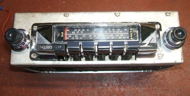
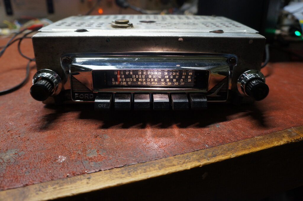
"Diamond Dot" refers to a series of Astor models. The Falcon radio being
described here seems to be known as a "5 Star" - note the stars on the
right side of the dial.
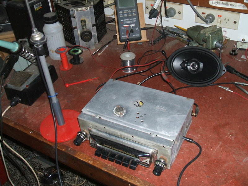
Set under test with new repro speaker.
This set came to me for repair from an owner of a 1965 XP Falcon. It had been installed in the dash of the car, but not connected. No speaker was present. In fact, it seemed the car had not been provided with a radio when manufactured, since the paint was intact around the speaker screw holes at the top of the dash. The absence of proper mounting brackets also suggested the radio was a recent addition, with the back of the radio held up by a piece of coat hanger wire. However, it was the correct radio for that model of car.
I was familiar with this model of radio, having first played around with one back in 1981. Back then I had no idea what it was from, but I knew it was made by AWA. Unusually, there is no model number printed on the radio, but I knew from experience that I'd have a circuit for something that was the same. I trawled through my AWA manuals and circuits and found the 991-A to match. These are listed as Falcon radios in the AWA manuals, and are also listed as XM prefixed models, suggesting XM Falcons.
The Circuit.
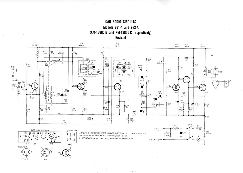
The set uses six transistors and is, as
standard by then, permeability tuned. VT1 functions as a tuned RF amplifier.
C1 and the aerial capacitance resonate TR1 to the input frequency. C1 is
made adjustable since different aerials may have different capacitances.
It is peaked at around 1400-1500Kc/s.
Transistor VT2 is an autodyne frequency
converter. That is, it is a self oscillating mixer. The oscillator coil
is L3, and tuned by L4 and C9 in series with C11. Feedback from the emitter
to cause oscillation is connected to the mid point of these two capacitors.
VT3 is the one and only IF amplifier stage.
Generally transistor sets use two IF stages, so this is a little unusual,
especially in a car set where utmost sensitivity is required. AVC voltage
is developed from rectifying the voltage across the 2nd IF transformer
primary (TR3). C16 shunt feeds diode MR1, and is filtered by R6 and C3.
Only the RF amplifier is AVC controlled.
Detection is by means of diode MR2 in
the conventional way. R17 would apply a small bias to MR2 to improve sensitivity.
The volume control has a loudness tap
for improved bass response at low volume. In addition, a tone control is
also provided, shunting more or less of the high frequency component to
earth via C24. C25 is a 4uF electrolytic to couple the audio into the first
audio amplifier, VT4. It should be replaced as a matter of course in these
radios, and is the most common cause of low volume.
The audio amplifier is a simple direct
coupled class A design, using transistors VT4, VT5 and VT6. DC feedback
is provided for stability. If the collector current of VT6 increases, the
voltage across R25 increases, increasing the emitter voltage of VT4, causing
VT5 to conduct less, and thus reducing the base current for VT6. Note that
VT6 is an NPN type. If C27 loses capacitance, volume will suffer, because
of the excessive negative feedback at audio frequencies than can now occur.
Further temperature stabilisation is provided
by thermistor TH1. As temperature increases, its resistance reduces, reducing
bias current. Collector load is a simple choke. The speaker is connected
directly across it. The choke prevents excess DC flowing through the speaker,
which would be problematic at the 500mA collector current. The 220R presumably
provides some protection against excess voltage breaking down the output
transistor, if the set is operated without a speaker.
Note that as most of the transistors are
PNP types, the set is operating with a negative supply rail. In the case
of a radio designed for negative earth, it means the set is constructed
upside down in the electrical sense.
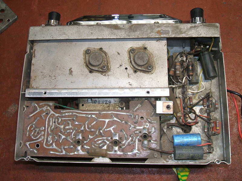
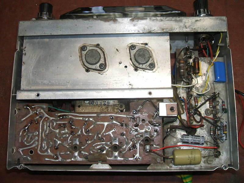
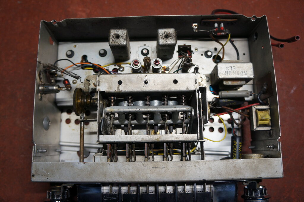
Despite being all solid state, no PCB is used. Construction is as per a valve set, with point to point wiring and tagstrips. The transistors are mounted in rubber grommets in the chassis. It's a method used for some of the first Australian transistor portable radios in the late 1950's. I was surprised to see it still being used in 1964 when this radio was built.
As is typical with Ford, the dial lamp is fed separately from the dash light circuit in the car. To those unaware, the red and black wires emanating from the radio would infer positive 12V (red) and earth (black). This is not so! Black is the positive 12V supply, and red is for the dial lamp. If one wanted to, the red and black wires can be both connected to 12V and the dial lamp will always come on with the radio, rather than only when the park or headlights are turned on. A fuse is not provided with the set, this being taken car of by a specific radio fuse in the car's fuse block. If one of these radios is used elsewhere, it is important to see the supply is fused. 2A to 5A would suffice.
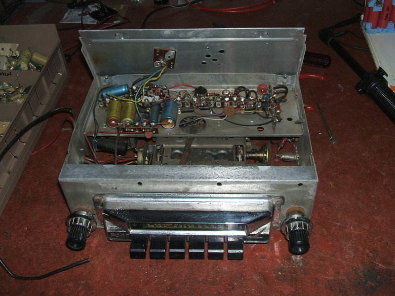
Very spacious layout makes servicing easy.
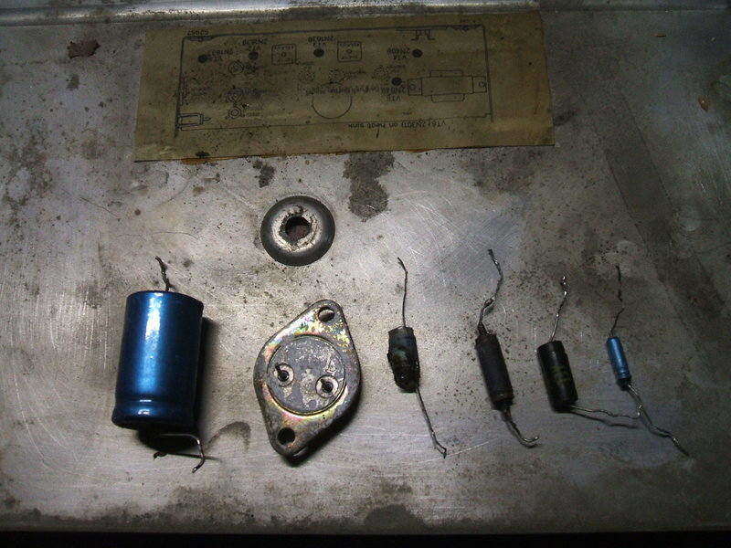
Dead parts replaced.
Repair.
First thing evident was a burnt up emitter
resistor (R25) for the output transistor (VT6). This usually indicates
the transistor has shorted, and this was confirmed. The resistor is one
ohm and from appearance looks like a small RF choke, being wound on the
body of a 1W resistor.
I replaced it with a 5W resistor. The
output transistor was replaced with an AD149 since I have a stock of these.
AD149 is essentially the European version of the 2N301.
Powering up the set showed normal current
consumption, so presumably the amplifier stage was operating, and those
were the only two damaged components. Connecting a speaker indicated all
was indeed good here, but with a lack of volume. Experience with mid 60's
AWA car radios has taught me that the coupling capacitor in series with
the volume control wiper (C25, 4uF) would be the culprit. These low value
blue Philips electrolytics are always suspect. Replacing it brought forth
good volume.
C29, the 640uF across the 12V supply,
had leaked electrolyte so it was replaced. All the other electrolytics
were tested and found to be OK. These AWA sets use an AEE "Microcap" type
of paper capacitor in other parts of the circuit. As is well known, paper
capacitors are notoriously unreliable in valve circuits because the paper
absorbs moisture, and also being organic, is unstable. In the case of low
voltage and low impedance transistor circuits, small amounts of leakage
is generally not a problem. For this reason, the paper capacitors were
left in situ, except for one which had suffered the not uncommon splitting
of the plastic encapsulating. A polystyrene capacitor mounted adjacent
to the output emitter resistor had suffered damage from the burn up and
was also replaced.
With the set electrically working, the tone and volume control were given a clean, and the push button tuning mechanism cleaned and lubricated.
For such a simple set, the performance was surprising. Early afternoon in the Blue Mountains brought in reception from 2GN (Goulburn) and 2AY (Albury).
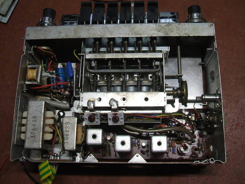
Second set as received for repair. Note two output transistors.
This set came from an early Falcon enthusiast
referred to me by the owner of the previous set. For the purpose of servicing,
I used the circuit for the 975-A. The complaint was that it received some
stations but with low volume. Immediately I thought of the audio coupling
capacitor (and subsequently confirmed this to be faulty). However, as this
set was from a lot further away and with the owner not personally known
to me, I considered the best thing would be to give it a full restoration.
This was agreed to, given that it will have the best reliability
possible.
There are some interesting differences
between this set and the previously described version. At the time, the
extra power transistor, and transformer to drive it, would have increased
the purchase cost. Also, this model has the power switch as part of the
push button tuner (AWA called it "Pressmatic"). The left most push button
switches the set off, and to turn it on any of the other buttons can be
pressed. Power output is nearly twice that of the cheaper set. This time
a PCB is used for all the small signal circuitry. I noticed the same PCB
has been used in several different models of AWA car radio. The audio output
and power supply circuit is all point to point using tagstrips.
Component side of the radio before parts were replaced.
The Circuit.
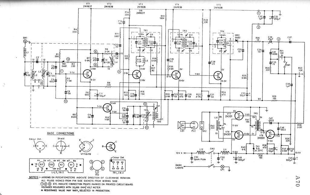
Circuit of the AWA 975-A.
As can be seen, the circuit is more elaborate
than that of the first set. As before VT1 is the RF amplifier. However,
now we have a separate oscillator (VT2) and mixer (VT3). There are also
now two IF amplifiers, VT4 and VT5. AVC controls the RF amplifier as before,
but also the first IF amplifier. Furthermore, there is an AVC overload
diode, MR1. This shunts the RF input with very strong signals. To see how
this works, note that the AVC is of the forward type; that is, collector
current of the controlled transistors increases, rather than decreases
with signal strength. This often provides better control characteristics
than reverse AVC in transistor circuits.
Turning now to VT1, we can see that as
signal increases, and thus AVC, the base current increases, and then so
does the emitter current. Thus, the voltage across R6, 680R increases.
Now, see how MR1 and R3 are connected. DC-wise, they are connected across
the emitter resistor. The more current that flows through the emitter resistor,
the more MR1 is biassed on, and the signal is shunted by it and the 220R
series resistor.
Unlike the six transistor set, AVC comes
from the detector diode (MR2). Again, a the volume control circuit has
a loudness and tone control. Note the presence of SW1 across the volume
control wiper. It mutes the audio amplifier when the push button unit is
actuated, so that one does not hear a rapid succession of stations as the
tuner goes from one end of the band to the other.
Transistor VT6 is the audio driver which
produces the push pull signal via transformer TR5. The output transistors
are again 2N301's and drive a tapped choke as their collector load. Note
that the speaker is not connected across the full choke. Temperature stabilisation
is again provided by a thermistor (TH1). Being push pull, this stage operates
in class B. This saves on battery current since current consumption of
the set is more dependent on the volume level than is the case with class
A.
Restoration.
Audio and power supply capacitors replaced.
This time I replaced all the paper capacitors with polyester and ceramic types. All electrolytics were also replaced. It is not a difficult job as service access is good, but just time consuming. It was noted the 12V supply choke L11 had been overheated. Although it hadn't actually gone open circuit, the insulation had burned off the winding. I rewound it with slightly heavier gauge enamelled copper wire. The radio functioned normally once this work had been done, but I had noticed an anomaly with the output transistor bias circuit. The circuit shows the bias current comes from R41, 195R. In actual fact this 195R resistor is two parallel 390R's. Current consumption with the volume all the way down seemed higher than it should be for a set with a class B output stage, and what caught my attention was that a 330R had been soldered across the two 390R's. It was not a factory job given how the soldering had been done. Why it had been done is not clear, because with it removed the audio quality was normal with no crossover distortion evident. With a class B stage, if initial bias is insufficient, crossover distortion makes listening unpleasant. With the foreign resistor removed, current consumption was much more satisfactory.
Not clearly visible, but all the paper and electrolytic capacitors
have been replaced.
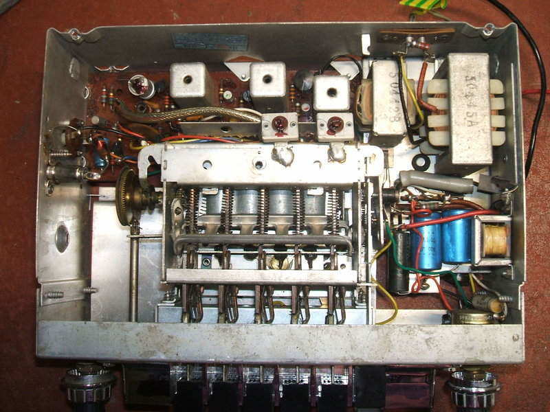
Next point of attention was the Pressmatic
unit. Some of the buttons were loose on their shafts, flying off when the
buttons popped out. Some were jammed and wouldn't disengage when pressed
in. This also resulted in not being able to manually tune the radio, because
the clutch was disengaged to the tuning knob. It transpired that the jammed
buttons were so because they had in the past come off the shaft and been
incorrectly replaced. The buttons have several slots into which the shaft
may be inserted. If anything but the central slot is used, the button is
tight against its neighbour. Once this was sorted out and the mechanism
lubricated, it worked very well. The final job was to fix the loose buttons.
They are a push fit on the shafts which have a slight toothed profile,
but if the plastic wears they fail to grip. One could use contact cement
to secure them, but I found the insulation off telephone wire to be perfect
for packing the gap between the slot in the knob and the shaft. The buttons
are a tight fit, but could be removed if need be.
The final job was to replace one of the
rivets securing the aerial socket. It had been replaced with a self tapping
screw which did not provide the right grip. An ordinary pop rivet works
well for this.
This set was fitted with a LED dial lamp. It's the brightest car
radio dial I've yet seen.
This third set was sent up from Melbourne for restoration; the six transistor 991-A. The complaint was the usual one of it being very weak. The usual cause is C25 open circuit, and indeed this turned out to be the main fault. Since this set was going back interstate, I replaced the other likely capacitors to get the best reliability. They are not expensive, and especially for the simpler tagstrip version, not difficult to replace. The 991-A would have the best serviceability of any transistor car radio that I've worked on.
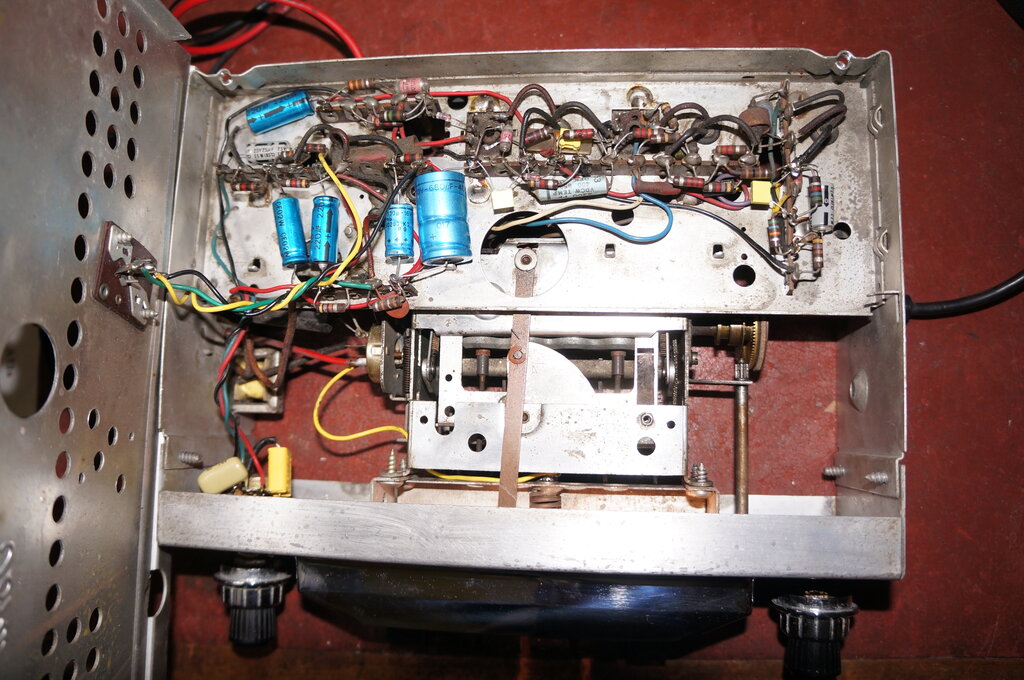
Capacitors replaced.
While replacing the capacitors, it's a good opportunity to clean out some of the grime on the chassis.
Spring at left is foreign.
The remaining job was the tuning mechanism.
Not surprisingly, the clutch was slipping. This happens because the clutch
material between the tuning control and the tuning mechanism becomes hard
and brittle. In this instance, someone had at some time added a spring
to provide extra pressure against the clutch. While that helped, the extra
pressure bears against the push buttons to the extent they have difficulty
returning to their positions.
I replaced the material on the tuning
control side of the clutch with cork gasket material. Needless to say the
foreign spring was removed. This, and lubricating the whole mechanism restored
correct operation.
As expected the radio worked normally at
power up. The dial light was a bright white. Someone had replaced the original
incandescent bulb with an LED E10 based bulb.
Performance was typical, with all the
Sydney stations easly received. By late afternoon, 4ZR from Roma in QLD
was coming in.
The owner had supplied a short "rubber ducky" style aerial. Out of curiousity I tested it, and just as well I did, because it was vastly inferior to the standard telescopic type that I used for testing. It may give passable results in a metropolitan area, but at my location 60km from the transmitters, it is not usable.
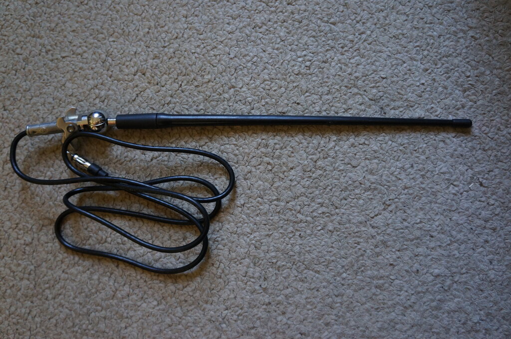
Not recommended.
The aerial is only 32cm long which does
not provide enough capacitive loading for the input tuned circuit of the
radio. The pickup was so bad that I wondered if the conductor inside the
rubber actually extends the full length. No doubt this aerial would work
better for VHF FM, and it's possible this is what it was designed for,
to the exclusion of AM.
It should be pointed out however, that
modern car radios are not critical with loading capacitance, and have in
fact dispensed with the trimmer adjustment. This aerial may be more suited
to them.