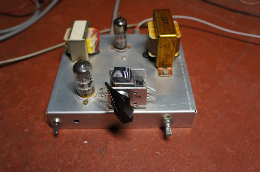
Built on the same chassis as the previous 12AT7 and 6BL8 receivers, the new design uses a 6ES8 twin triode.
Built on the same chassis as the previous 12AT7 and 6BL8 receivers,
the new design uses a 6ES8 twin triode.
One of the common TV valves in Australia
is the 6ES8/ECC189. This is a frame grid twin triode released by Philips
and Mullard, intended as a cascode RF amplifier for VHF TV tuners. It replaced
their earlier 6CW7/ECC84.
With so many of them in my collection,
I had attempted to use them for a super-regenerative receiver. There was
certainly no difficulty in getting the circuit to oscillate and quench,
but the problem was poor sensitivity compared to the 12AT7.
The circuits used were essentially the
same those used for the 12AT7,
with only the heater connections rearranged. The problem seemed to be an
excessive quench signal compared to the audio signal.
In view of the success with the 6GK5
(another frame grid triode), it was decided to have another go with the
6ES8. The receiver to be described is the outcome of what I learned with
the 6GK5, and turned out to be quite a good performer.
Introducing the 6ES8/ECC189.
The following article comes from "Mullard
Outlook", November/December 1959. The 6ES8 first appeared in Australian
TV tuners made by Philips in 1960. Europeans would know this valve as the
ECC189, but would be more familiar with the
series heater version, the PCC189.
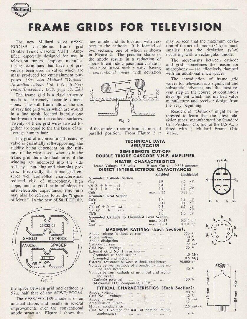
As can be seen, the mutual conductance is 12.5mA/V, which is just over twice that of the 12AT7. However, the 6GK5 is 15mA/V, so it would seem that if that valve could be made to work, then so should the 6ES8.
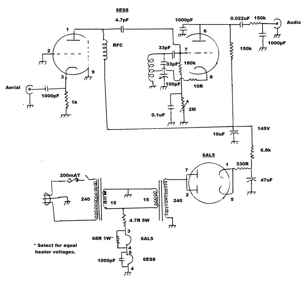
The circuit is essentially that of the
6GK5 design, but with the extra triode as an RF amplifier. As was done
with the 6GK5 receiver, I used tapped coil feedback instead of the cathode
choke previously used. No one likes winding coils, and it makes the receiver
simpler and tidier without it.
Again, the secret is to get the correct
plate waveform, and this achieved by a low value resistor between the cathode
and tapping on the coil. In this case, 10 ohms was about right.
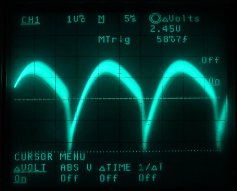
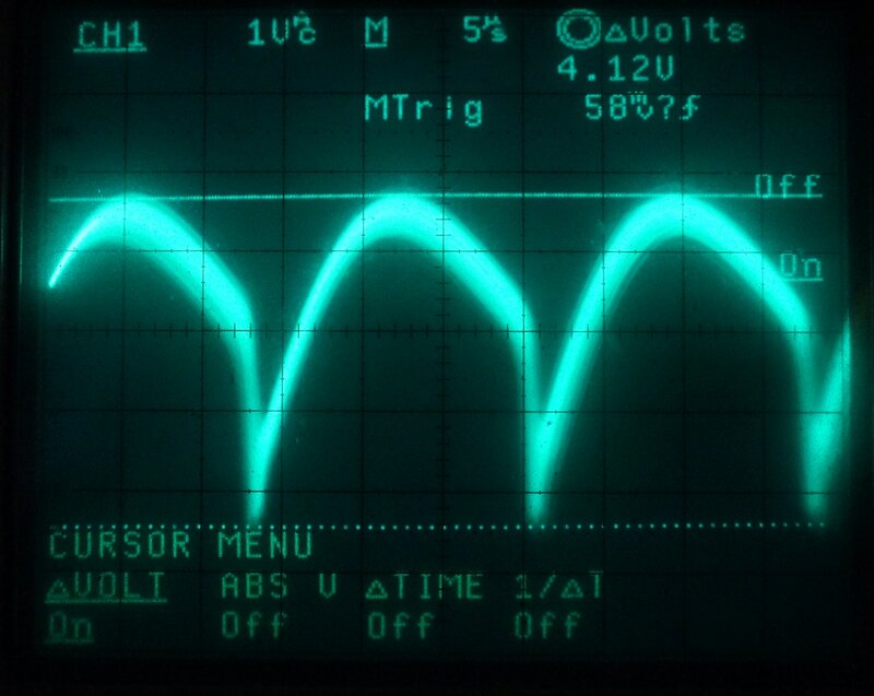
Plate waveform of the detector.
The detector triode operates as a Hartley oscillator, with cathode feedback on the oscillator coil. The coil is tuned through the 88-108MHz band with a 100pF variable capacitor in series with a 33pF fixed capacitor. Ideally, a 15pF variable capacitor should be used on its own, since it will provide much more linear tuning. However, I have plenty of 100pF variable capacitors, in the form of the oscillator section of a once popular MW superhet tuning capacitor, made by MSP (AWA).
The grid leak components, being the 180k and 33pF, set the quench frequency. That is the frequency at which the VHF oscillator is interrupted. For FM broadcasts, around 28kHz works well, since it is low enough for good sensitivity, but high enough to prevent most intermodulation distortion. With this particular receiver, I found that with a slight reduction in volume, sound quality was even better at around 57kHz.
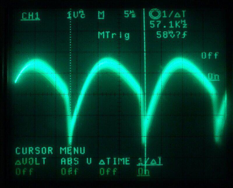
With reasonably strong signals, 57kHz gave good sound quality.
The operating conditions must be adjustable
so that the triode can be taken close to the point just above where it
starts oscillating. This is essential for good sensitivity. Most published
circuits simply vary the plate voltage, but experience shows that although
the valve can be taken to this point, sensitivity is poor.
As explained with my original 12AT7 circuit,
varying the grid voltage instead makes a huge improvement. It appears that
the oscillator is more easily triggered when the grid is taken close to
cut off, rather than by dropping the plate voltage. And it is this triggering
of the triode into oscillation that determines the sensitivity.
Controlling the grid voltage simply entails
taking the earthy end of the 180k grid leak resistor to a variable negative
voltage. Alternatively, the cathode can be raised by a similar positive
voltage. Looking at the various super-regenerative circuits around this
site will show examples of how that is done.
In this instance, as per the 6GK5 design,
the negative voltage developed at the grid is itself used as the control
voltage. As the 2M rheostat is increased in resistance, the grid voltage
becomes more negative. The 0.1uF bypass prevents the 2M rheostat influencing
the quench frequency. However, adjusting the grid voltage does
to some degree adjust the quench frequency, but this provides a useful
adjustment if there should be intermodulation distortion with particular
program material.
Ideally, the grid leak components are
set so that the quench frequency is about 26kHz with the triode almost
at cut off.
The plate circuit is just like all the other designs around the site, with the 1000pF RF bypass, and quench filter comprising the 150k and another 1000pF. Given the high gain of the 6ES8, and its willingness to oscillate at low plate current, higher audio output can be had by taking the plate load to 150k, instead of 56k as used with the 12AT7.
The RF amplifier is again, the same untuned grounded grid design, which I've used previously many times. The plate load is a quarter wavelength RF choke, of the type which has been used in the other circuits. One change I did make this time was to eliminate the cathode choke. Given that the circuit is untuned, it seemed that this choke might not actually be required. The plate choke would still act as a high pass filter. It certainly seems to work.
Constructional Points.
Those who have read the articles on theNew
12AT7 FM Tuner and the 6BL8
or 6U8 Super-Regen Receiver, will recognise the chassis used with the
new 6ES8 receiver. Yes, it's the same one rebuilt with the new circuit.
As I have plenty of other 12AT7 receivers, and one 6BL8 receiver in use,
I was not losing anything by doing this.
The power supply uses modern transformers
back to back. The mains feeds a 240V to 15V 500mA transformer, which then
feeds another 15V 150mA to 240V transformer in reverse. The output is half
wave rectified by a 6AL5/EB91 to produce about 178V across the 47uF filter
capacitor. A 6.8k resistor and 10uF provides further filtering, resulting
in a B+ of about 145V. Total current consumption is 4.8mA.
The valve heaters are wired in series,
and fed from the 15V AC supply via a 4.7R resistor. Since the 6ES8 draws
a nominal 365mA, and the 6AL5 draws 300mA, a resistor needs to be shunted
across the 6AL5 heater, so that both heaters run at 6.3V.
Note that the 6ES8 is not designed for
series heater use, so the 365mA is a nominal figure, and may vary with
individual valves. For this reason, the 68R resistor may need to be adjusted
for the particular 6ES8 used. If one uses a PCC189, no shunt resistor is
used, since this is a 300mA series heater valve. In this case, the total
heater voltage will be 13.9V, and the 4.7R needs to be reduced accordingly.
Obviously, any other suitable power supply
can be used to provide the 6ES8 (or PCC189) with suitable heater
voltage, and a B+ of 140 to 170V.
Despite the 145V B+, I used 100V disc ceramics
for all the pF value capacitors. I've never had one break down in this
or my other super-regen circuits. The resistors can all be 1/2W, except
the 4.7R in the heater circuit (5W) and the 68R shunt (1W), and the 6.8k
filter (1W).
The filter electrolytics need to be rated
at least to the unloaded B+ voltage; 200V will do for the circuit as shown.
A 15pf or 20pF tuning capacitor is preferable
instead of the 33pF + 100pF tuning capacitor shown.
The aerial coil is four turns of 1.6mm
tinned copper wire, 10mm diameter. A 10mm drill bit is a convenient
winding former. The width of the coil is about 10mm, and by spreading or
contracting the width, some adjustment of frequency range is obtained.
The cathode tapping is at two turns.
The RF choke is wound with 75cm of 26
gauge wire on a 6.35mm former. It is not super critical, and a slight difference
in wire gauge or former diameter is not critical.
DC Heater Supply.
It was found with the 6GK5 that most examples
showed 50Hz hum in the audio output. The 6ES8 was also found to be susceptible
to this problem.. Several 6ES8's were tried in the circuit, and as with
6GK5's, the amount of 50Hz modulation varied between individual valves.
The problem is evident as the audio output superimposed on a 50Hz sine
wave. Surprisingly, it was not intrusive on the program material. *See
below.
Nevertheless, one should use a DC heater
supply if constructing this circuit. To see one way of doing this, see
the 6GK5
portable receiver.
**Update Re
50Hz Hum**
It appears that the use of a cathode tapping
on the oscillator (aerial) coil instead of an RFC is the cause of mains
hum being present in the audio output. None of the circuits using an RF
choke in the cathode circuit have exhibited this problem.
The mechanism by which this occurs is
probably a form of modulation hum, where 50Hz from the heater is coupled
by the heater to cathode capacitance, directly into the tuned circuit.
If you wish to use the cathode tapping
method, and the hum is not a problem, there is no reason not to do so.
Otherwise, the valve must be heated with DC, or the original cathode RF
choke circuit used.
**Update Re
Grid Voltage Control**
The method of using the grid leak voltage
as the actual regeneration control voltage works well, and simplifies the
circuit. However, it does not provide complete cut-off. For 'normal' reception
this is not important, and indeed, the self regulating feature is convenient,
and appreciated by less technical users. Where utmost sensitivity is required,
the adjustment range needs to be able to take the detector just out of
oscillation. Therefore, for any kind of 'quality' or 'DX' type of receiver,
the grid resistor should be taken to a variable negative voltage supply
instead.
Performance.
Quite good reception of 2NUR, on 103.7MHz,
transmitting at 10kW from 135km away was obtained. This transmitter is
directional and aimed away from my location. All the main Sydney, Newcastle,
and Illawarra stations are also received well from my location in the Blue
Mountains, along with many of the low power public stations. This is with
an outdoor five element Yagi.
Tested with a signal generator, 3uV is
quite noisy and not entertainment quality. 10uV is slightly noisy but the
noise is not excessively intrusive. By about 30uV, the signal is quite
clear. For completely noise free reception, at least 150uV is required.
With the 33pF + 100pF tuning capacitor,
the frequency range is 84 to 125MHz. Of course, aircraft band transmissions
can be easily received with this extended tuning range.
Improved 6ES8 VHF Receiver.
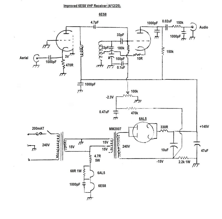
Two improvements were done to the receiver.
First was the provision of a negative supply for regeneration control.
Since the grid leak derived voltage cannot take the valve to cut off, a
separate supply is required. The power supply was modified so the filter
resistor is now in the negative supply and functions as a back bias resistor.
The -15V produced feeds the regeneration control via a 470k resistor to
provide about -2.3V of control voltage. The positions of the 10uF and 47uF
filter capacitors was swapped to provide for better operating conditions
for the 6AL5.
The RF amplifier gain was increased by reducing the cathode resistor to 470R. This triode now passes about 6mA. Previously, the gain as measured on a 100MHz CRO, was one. Gain is now approximately 2.2 times. A further increase in plate current would probably improve this further, but the existing power supply is not up to providing the extra current. 1uV can be detected but is certainly not usable. Around 3uV and the program material can be understood. At around 15uV the noise is low enough for the signal to be of of entertainment value. Despite the ineffeciency of slope detection, the difference between AM and FM sensitivity is not as great as expected.