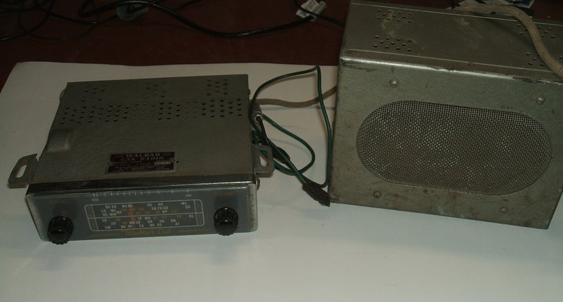
This two unit car radio was made in the late 1950's by A.W. Barrs. Wally Barrs was the proprieter of the company, hence the name "Walbar". The address of the company is shown on another radio in my collection to be 70 Princes Hwy, Arncliffe - a southern suburb of Sydney near the airport.

Walbar was a well known Australian manufacturer of car radios and accessories, such as aerials, but did not venture into domestic receivers.
The two unit concept came about because
of the difficulty in fitting single unit sets into small cars, usually
of European or British origin. Generally, one section contained the power
supply and the other was the actual receiver. The receiver was compact
enough to mount under or in the dashboard, while the bulky power supply
could be mounted on the firewall. In some cases, the receiver would mount
inside the glove box if there was no other space. In some instances, the
speaker was mounted inside the power supply enclosure, or it would be in
a third unit, again mounted wherever space could be found.
Variations of the scheme included having
the receiver containing only the RF amplifier and frequency converter,
and then conveying the IF to the second unit which contained the IF amplifier,
detector, audio, and power supply stages.
Some two unit sets included the audio
stages, or just the audio output, in the power supply unit.
The two unit design is quite different
to the older Bowden cable sets. In these, the receiver is one unit;
with or without the speaker built in, but the occupants of the car operate
the set by a mechanical remote control. Because the remote control has
only the knobs and dial, it takes up little space and is easy to mount
on or in the dash, or on the steering column.
The Bowden cables are constructed in the
same way as a speedometer cable and connect the remote control to the receiver
in the same way. However, as it is not possible to have sharp bends in
the cables, there are still limitations with how these sets are installed.
As sets became more compact with the introduction of miniature valves,
IF transformers, etc, the Bowden cable type of set was obsolete by the
end of the 1940's. Single unit in dash models started to become prevalent
in the early 1950's and remained the standard for most Australian and American
cars.
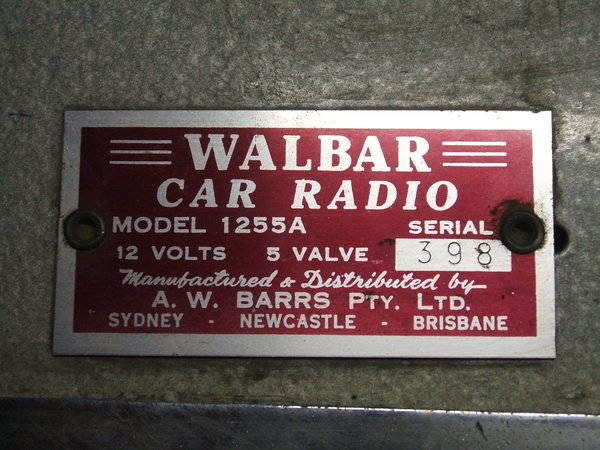
The Walbar 1255Adescribed in this article consists of the receiver, including the audio output stage, in the dash unit, and the power supply and speaker are inside the second unit. This second unit is designed to attach to the firewall with a 1/4" Whitworth bolt. Connection between the two is by a shielded cable fitted with a four pin plug.
The set was in quite good cosmetic condition, and by appearances was of late 1950's manufacture. In fact, one number stamped onto the speaker frame suggests 1959. With the PVC wiring, and components used, this would appear to be correct. The knobs were missing, and with no idea what the originals looked like, I simply replaced them with some generic Aegis types.
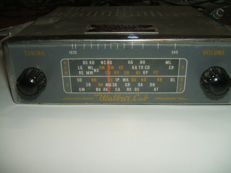
Simple dial. Very little of the light from the dial lamp actually
reaches the dial.
It is a no frills design with a very plain
dial. Like a lot of car radios, the dial only showed one or two states.
This was simply because for a readable dial, there isn't enough room for
all the Australian stations. If one was to relocate interstate, a new dial
could be obtained. Car radio dials that did include all states showed only
the main stations.
This particular set has only Queensland
and NSW stations. An interesting feature is the high end of the dial is
calibrated to 1620 Kc/s, yet there were no stations above 1600Kc/s at the
time.
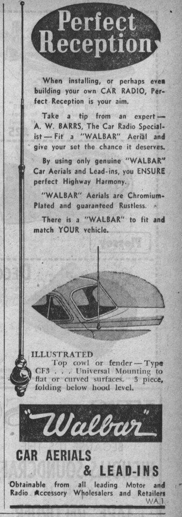
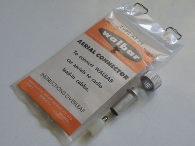
Walbar was manufacturing car radio aerials and accessories prior
to the actual car radios.
The Circuit.
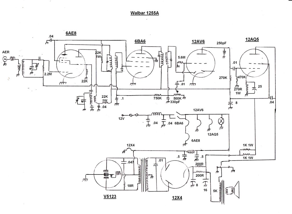
Some of the condensers did not have their markings visible so the values are not shown.
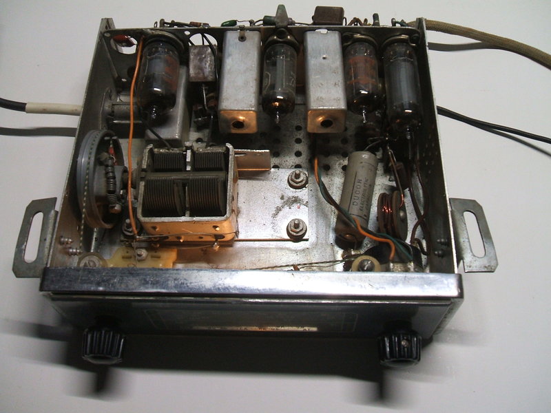
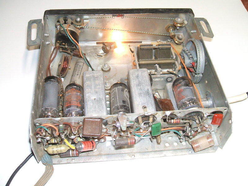
In keeping with the no frills design, there is no RF amplifier in the 1255A. However, looking at the chassis shows that there was an RF amplifier in another model. One can see the two holes for 7 pin valves, no doubt a 12BA6 or 6BA6 RF amplifier and 12BE6 or 6BE6 converter. In the location occupied by the 6AE8 frequency converter in the 1255A, it can be seen this is where the RF coil would be. Furthermore, the bracket mounting the two gang tuning condenser is long enough to mount a three gang unit. The tuning condenser is a Philips type.
Original condensers still in place. Two vacant holes can be seen
either side of the 6AE8 which would contain the extra valves in the RF
amplifier equipped version.
While permeability tuning had become standard for car radios by the end of the 1950's, the Walbar has kept with the older variable capacitor design. Incoming signal feeds into the aerial coil via an ignition filter choke. This functions as a high impedance to high frequency ignition interference. Aerial coils for car radios have a much tighter coupling between primary and secondary windings than do domestic receivers. This is simply because of the short aerial and limited signal pick up. As a result of the tight coupling, the capacitance of the aerial has considerable effect on the tuning of this coil. In common with many other car radios of the time, the aerial input is via a bayonet socket of a type which originated in the U.S.
Frequency Converter.
The frequency converter is a 6AE8 triode
hexode, otherwise known as the X79 in the UK. This valve, created by Marconi-Osram,
was the probably the last frequency converter valve developed for radio
use. The circuit is conventional, with the triode performing as the local
oscillator, and the incoming signal fed into the hexode. Because the local
oscillator signal modulates the electron stream of the hexode by the third
grid, the two signals are mixed, producing the usual sum and difference
signals which appear at the plate.
It was not possible to identify a few
condensers because of how they were positioned, but it would be safe to
say the padder condenser is probably 425pF. The oscillator grid condenser
is probably 50 or 100pF. The hexode grid condenser was measured at around
80pF. These latter two components are not particularly critical, but the
padder most certainly is, so as to provide correct tracking between the
local oscillator and RF input circuits.
It is a curiosity why the hexode grid
circuit is fed via a condenser and 2.2M grid resistor, when simply connecting
the aerial transformer secondary to the grid would eliminate these two
components. In fact, the earthy end of the secondary is already connected
to the AVC line.
Cost Cutting.
The IF amplifier is a 6BA6 used in the
conventional way. It feeds one of the detector diodes in the following
valve, a 12AV6, to produce the audio and AVC. The minimalist design is
evident in that the converter and IF valves have no cathode bias components.
The only way these valves obtain any negative bias is from the AVC line,
which of course is dependent on signal strength. If the set is not
tuned to a station, there is the possibility of excess cathode current.
Hopefully, the common 22K screen resistor will reduce this.
Secondly, there is just one 330pF condenser
for IF filtering at the volume control. Normally, an RC filter consisting
of a 47K resistor and two 100pF condensers would be used here.
The 12AV6 triode operates normally, using
a high value of grid resistor to obtain the necessary bias. This works
because of the proximity of the grid to the cathode in high mu triodes.
The grid picks up a negative charge due to the electron stream emitted
from the cathode. For this scheme to work, the resistor has to be fairly
high; 4.7M to 22M are values usually used here. If the resistor is too
low, the electrons are discharged too rapidly resulting in too low of a
voltage.
It is strange that the unused detector
diode was just left floating. Normally, when only one diode is required,
both diodes are connected in parallel. If anything, the diode voltage drop
would have to be reduced allowing for increased detector efficiency.
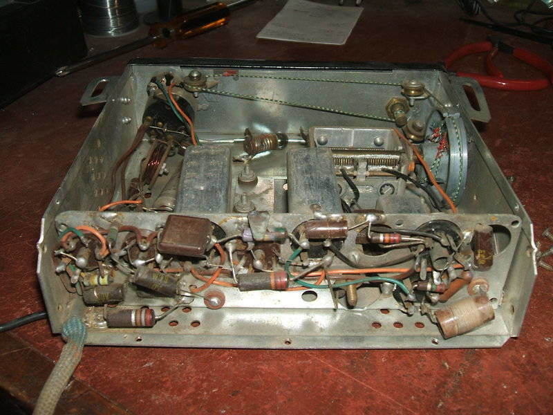
Valves from left to right are 6AE8, 6BA6, 12AV6, 12AQ5.
The IF transformers are mounted by soldering their mounting tags to the chassis. Not surprisingly, a couple of these joints were cracked, leaving the transformers to move around.
Output Stage.
Here, a 12AQ5 is used in the conventional
way, with a 270R bias resistor and 25uF bypass condenser. There is the
usual plate bypass condenser, but here it's rather higher than normal.
Typically, it would be .01uF, but here it is .04uF. Perhaps this was required
because of insufficient IF filtering before the volume control.
Power Supply & Speaker.
Unlike the U.S., 12V car electrical systems
were quite common in Australia, and had been for some time prior to the
mid 1950's. This was because of the prevalence of English cars here. And
so, vintage car radios here are often found to be 12V. American sets, however,
will usually be 6V unless made after the mid 1950's.
The Walbar 1255A is 12V. Undoubtedly,
there would have been a 6V version made as well. Many, if not most, models
of car radio were available in 6 or 12V. The changes are simple; essentially
a rewire of the heater circuit from parallel, to series parallel, or replacing
the valves with 12.6V heater types. The vibrator and transformer are also
changed, and a 12V dial lamp completes the modifications.
In the 1255A, 12.6V heater valves are
used, except for the converter and IF. This would be because the 6AE8 is
not available with a 12.6V heater. The simple way out of this problem is
to connect its heater in series with another 6.3V valve with the same heater
current (300mA) - in this case the 6BA6.
The incoming 12V supply is fed via an LC filter to the power switch. This is the usual type of combined volume control with double pole switch. From there, the 12V feeds the dial lamp and valve heaters in the under dash unit. An additional feed supplies the 12X4 rectifier heater and vibrator mounted in the other enclosure.
The power supply is simple and conventional, using an Oak V5123 non-synchronous vibrator, transformer, and 12X4 rectifier. A .01uF timing capacitor (buffer) prevents contact wear by reversing the transformer primary voltage, when the contacts open, so there is minimal voltage across them at this time.. On the primary side is a .047uF for RFI suppression. In series with this is an 18R damping resistor. One thing is rather strange, and that is the B+ filtering. There is only 100R of resistance between the first (8uF) and second (16uF) filter condensers. Such a low resistance won't do much.at the low current involved. However, because of the waveform of the rectified vibrator output, not as much filtering is required as when the rectifier input is a sine wave from a mains supply. The filtered B+ feeds the speaker transformer also mounted in this box. There is a further RC filter in the under dash unit, for the front end valves and 12AQ5 screen.
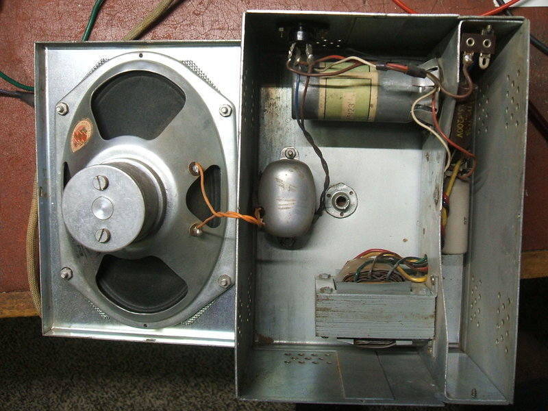
Inside the power supply /speaker box. The 12X4 is behind the vibrator.
The speaker is an oval type, made by EMI
(HMV) of about 6" x 4". The speaker transformer had been replaced, with
the new one mounted to the back of the box, rather than the chassis where
it originally was. It would appear that this had been the only ever fault
in the radio. No other components had been replaced. The particular type
of resistor used in this set is one that I've found to be reliable, and
the AEE Microcaps are generally a lot better than the usual wax dipped
types - although their plastic outer covering tends to crack and fall off.
So, for its time, it would have been a very reliable set.
Two of the AEE Microcaps did not have readable values, so they were measured prior to replacement. Even if leaky, the capacitance value will not be markedly different. An unusual aspect of these condensers is the prolific use of .04uF types. Not .047 or .039, but .04. The other non standard value was the 750K AVC isolating resistor.
Inside the power supply, the only part needing replacement was the buffer condenser. I used a 3kV ceramic type for replacement. Surprisingly, the original paper type actually measured very low leakage when tested with a 500V Megger.
New ceramic buffer capacitor fitted.
Powering Up.
Because the vibrator hadn't been used
for many years, it did not prouce any output because of oxide on the power
contacts. After a few minutes running, one contact cleaned itself sufficiently,
but the other was a bit more stubborn, so I quickened it up by connecting
this contact directly to a current limited power supply at about 20V.
B+ at the output of the 2nd filter condenser
was about 190V which was fairly typical, although a little low. Observation
of the vibrator waveform showed the duty cycle was less than normal, and
this also showed up in that the buffer capacitance seemed a bit on the
low side. As the value of buffer capacitance depends on duty cycle, among
other things, if the duty cycle is lower than that of the vibrator used
to design the circuit, the buffer capacitance is then insuffucient.
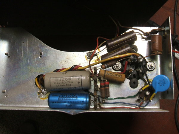
Rear of under dash unit after condenser replacement. The ignition
interference coil can be seen in the bottom right corner. Note the tiny
slot in front of the dial lamp - no wonder the iluumination is so poor.
As for the performance, the sensitivity
appeared poor for a car radio. In fact, considering this is a superhet,
my home made
five valve regenerative car radio actually pulled in more stations,
more clearly.
Fotunately, the excessive top cut capacitance
in the 12AQ5 plate circuit didn't seem to make the sound as mellow as I
thought it might.
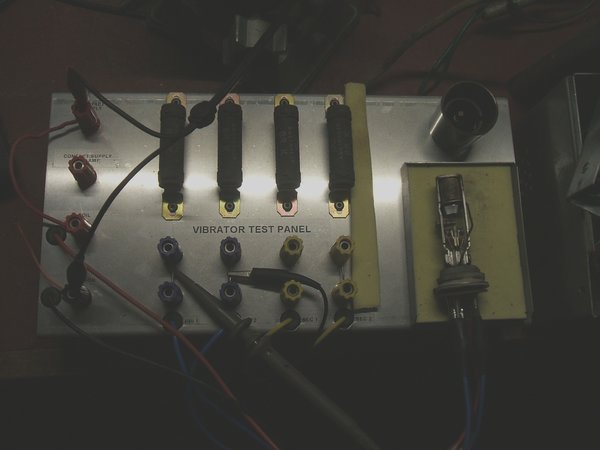
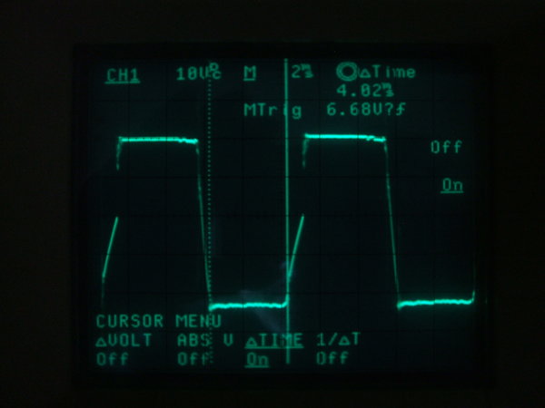
Vibrator undergoing analysis.
As suspected, the duty cycle was low. Instead of 4ms, the contacts were making for 3.36ms. As the B+ voltage was not excessively low, I could have simply increased the buffer capacitance to compensate, and thought no more of it. However, not being one who encourages changing component values in commercially made circuits, and because the Oak vibrator is easy to work on, I thought I should do the correct thing and restore it to specifications. I had noticed also that the vibrator did not always start, which indicated something wrong with the driving coil contact adjustment. This adjustment is easily done by means of a set screw and locking nut. Indeed, it seemed odd that there was so much pressure on the normally closed driver contact. Often the vibrator would need a thump to get it started. Application of 12V was not sufficient to get the contact to open when the reed swung over. Once this was readjusted, the vibrator reliably started every time with less than 5V. I can only put this excessive contact pressure down to human error when the vibrator was initially set up at manufacture.
Right on spec, correct duty cycle restored.
To obtain the correct duty cycle entails
carefully bending the arms of the fixed contacts, with a narrower spacing
obviously increasing the duty cycle. From information from AWA, (the makers
of MSP/Oak products in Australia), the vibrator contact adjustments have
a 5% tolerance at 40% duty cycle. This means 3.8 to 4.2ms is acceptable.
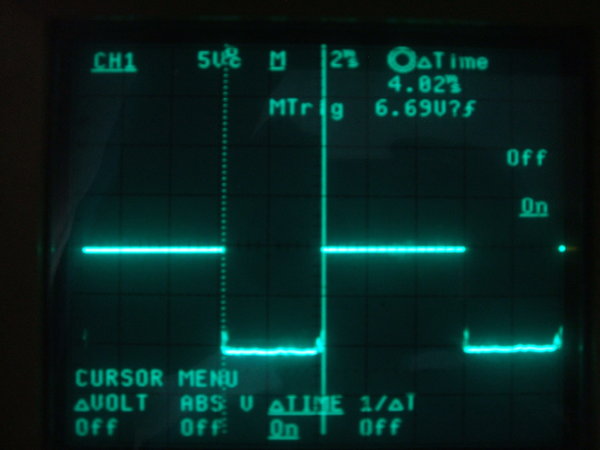
After both contacts were adjusted, the
full wave operation was checked:
Full wave operation into a resistive load is the most accurate way
to test a vibrator. A slight unbalance can be seen, with the other
contact making for 3.88ms, but it was not felt worth trying to improve
upon this.
The contact condition was good with no
pitting. With the vibrator now readjusted, it was re-installed and
the buffer waveform checked. No contact sparking was visible.
It is worth noting that the reduction
in duty cycle which occurred here (from 80% down to 67%) would have
resulted in poor starting had the vibrator been a shunt drive type. If
that had been the situation, the vibrator would definitely have to be readjusted
for it to continue working.
So, why the reduced duty cycle? From the
black deposits spread around the inside of the vibrator can, it would indicate
contact erosion from contact sparking. This is certainly not normal. Unless
a vibrator has been sparking, the inside should be spotlessly clean. When
I tested the power supply after recapping the radio and readjusting the
vibrator contacts there was no sparking at all, the current draw was normal,
and the vibrator waveform was correct.
Possibilities are:
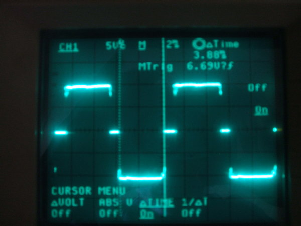
Waveform across full primary of the transformer.
Apart from slight unbalance, the waveform
was what it should be. Vibrator life should now be normal, and so long
as not to be worth worrying about.
The B+ had increased to about 213V.