The Mallory Vibrapack has been described
elsewhere on this site, but as a brief introduction, they were a series
of pre-built vibrator power supplies. Mallory was the world's largest vibrator
manufacturer, and also manufactured complete power supplies.
The purpose of a vibrator power supply
is of course to provide high tension, usually to operate valve circuits,
from a low voltage accumulator; typically 6, 12, 24, or 32V. Such situations
are typically automotive, aircraft, marine, or low voltage home lighting
plants. The output voltage depends on the valves used and is usually from
90V for miniature battery valves, up to 300V for some transmitting and
high powered amplifier types.
Since vibrator power supplies require
careful design and construction if long vibrator life is to be obtained,
and to ensure freedom from RFI, many of the vibrator manufacturers offered
a complete modular unit. In this way, matters such as shielding and correct
vibrator operation would be taken care of by those best suited to do so.
All the user has to do is simply connect
the input to the battery, and B+ is provided at the output. The smaller
Vibrapacks can be mounted on the chassis of the equipment to be powered,
and they take up no more room than a mains transformer and rectifier valve.
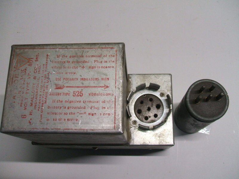
The VP-401.
Mallory manufactured a range of Vibrapacks
for general use, which were widely advertised in electronics and amateur
radio magazines.
However, some were made for specific manufacturers.
The VP-401 is one of these. It is not listed in any of the catalogs, so
the ratings are not known. The only information immediately available was
that the input was 6V.
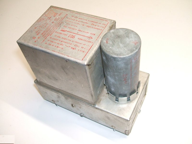
From various numbers stamped on the "bathtub"
capacitor and chassis, it would appear this VP-401 was made in 1949. It
was noticed that there was some scratches around the vibrator socket holes
suggesting the unit had been used.
Input and output terminals visible. Note the seam of solder around
the base of the transformer.
525 Vibrator.
As received, the vibrator was missing.
The absence of a rectifier valve, and that the vibrator socket was a seven
pin reversible type, indicates a synchronous vibrator was required. The
labelling on the top of transformer indicated the type to be a 525. Interestingly,
this does not appear in the Mallory catalogs I have, but the Radiart catalog
does give an equivalent. It would appear the 525 is not a "consumer" type.
This is in fact all very reminiscent of
another "non-consumer" Vibrapack, the
G368. However, working back through the Radiart equivalents, we find
it is as expected, the same as the more common 725. In essence, any 6V
reversible type could be used.
The Circuit.
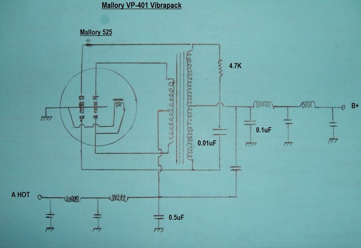
Unmarked capacitors are disc ceramics, presumably 0.02uF.
As with all the other Vibrapacks so far
described, the circuit is completely conventional. The 6V input, from the
"A HOT" terminal feeds the transformer primary centre-tap and the vibrator
primary contacts switch either end of the primary to earth alternately.
This creates an alternating magnetic flux in the transformer core, and
in the usual way, the secondary winding provides a much higher voltage.
As this voltage is also AC, rectification
and filtering is required to convert to DC, before being applied to the
valves in the equipment being powered. Any of the standard full-wave rectifier
circuits can be used, but in many situations the vibrator can perform this
function using an extra set of contacts. The advantages of so doing is
that a rectifier valve is eliminated, saving (typically) 600mA of extra
current at 6V. Furthermore, the voltage drop across the vibrator contacts
is zero, compared to the higher voltage drop across a rectifier valve.
Thus, a higher efficiency is obtained. The possible downside to this is
that the input supply must be a certain polarity to ensure the output polarity
is correct.
If for example, the power supply is designed
for a negative earth vehicle, and then used in a positive earth vehicle,
the output would have reversed polarity. It is then necessary to reverse
the connections of either the primary or secondary transformer windings
(but not both).
For this reason, the reversible vibrator
was developed. It is used in all the Mallory Vibrapacks using synchronous
vibrators, and is described further here.
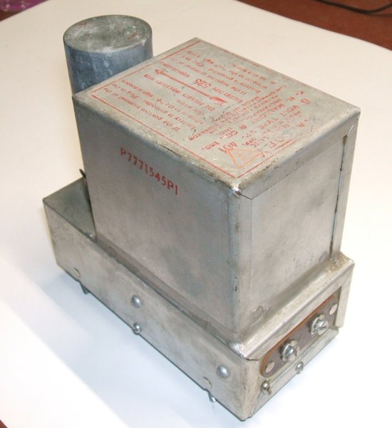
Top view of the VP-401 with vibrator socket visible. Note the symmetrical
design of the reversible socket.
Across the secondary is the usual timing
or buffer circuit. A 0.01uF condenser controls the rate at which the voltage
reverses when the vibrator contacts open. This ensures that there is minimal
voltage across the primary contacts when they actually close and open.
Hence, sparking and contact wear is avoided. In series with the 0.01uF
is a 4.7K 1/2W resistor to damp oscillation caused by the transformer's
leakage reactance.
It is not essential, but provides a smoother
topped waveform. Many texts written by those unfamiliar with vibrator power
supplies claim that this resistor is a protective feature in case the timing
capacitor fails - presumably their authors are not familiar with resistive
damping, and cannot visualise any other purpose for it. In actual fact,
proper fusing of the supply is all that is necessary to protect against
timing capacitor failure.
Rectification is achieved in the usual
way, by alternately switching each side of the secondary winding to earth,
causing the centre-tap to always be positive.
Filtering.
Compared to the other Vibrapacks examined
so far, the VP-401 is extensively filtered. It would appear it was designed
for a sensitive receiver, and one that covered a wide frequency range.
Both the input and output circuits have
a two section Pi filter. In each case, the two chokes are obviously designed
to be effective at different frequencies.
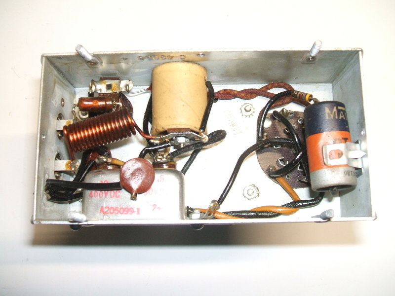
Underside view. Filtering components are on the left. At right is
the timing capacitor and damping resistor.
It can be seen in the above photo that
the 6V input is fed through a choke of few turns of thick wire. Then, it
feeds another choke of many more turns. This is the one wrapped in paper.
The choke of lesser inductance would be more effective at higher frequencies,
while the larger choke would be more effective at lower frequencies.
Similarly, on the output circuit, the
B+ feeds a litz wire choke of many turns (not clearly visible), and then
what looks like a VHF choke of a few turns. There is prolific bypassing
with ceramic disc capacitors, as well a the usual 'bathtub' paper types.
One interesting feature is that one of the disc ceramics is connected between
the centre-taps of both the primary and secondary windings. Ordinarily,
bypassing the B+ to the 6V line would cause one to assume that any noise
on the 6V line would be transmitted to the B+ output.
It would appear this was one instance
of where RFI elimination was more art than science.
The disc ceramics would appear to be 0.02uF,
going by the coloured stripes; red, black, green. The value would not be
critical.
Interestingly, there are no 100R resistors
across the primary contacts, as has been with the other 6V Vibrapacks.
As a final detail, the base of the transformer
has actually been soldered to the chassis, with a continuous seam of solder.
This has not been done with the other Vibrapacks and would indicate the
emphasis on shielding.
Note that the output is filtered for RF only. An external filter is required for the B+, and can be conveniently mounted in the equipment being powered. Typically, a Pi-filter with two electrolytic condensers and a choke or resistor is required.
Getting it Going.
As with my previous experiences with Vibrapacks,
I expected the paper timing capacitor to be in good enough condition for
at least a short term test. Over time, however, the capacitor body has
been deformed by a rather aggressive spring clamp. Nevertheless, it was
decided to try it anyway.
A Mallory 5 pin 6V vibrator was found
in the collection. The printing had been worn off so it was not possible
to determine the type, except that it was 6V.
Upon applying 6V input, the vibrator started
straight away, and the output was around 280V. The waveform was as expected,
although one set of primary contacts could do with cleaning. Neither the
4.7K or 0.01uF became warm.
Judging from the transformer size, it
would probably be safe to assume a maximum B+ current of 50mA.
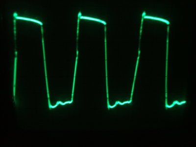
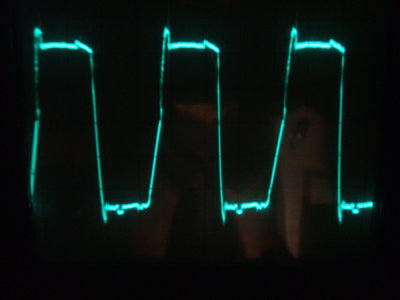
Primacy waveforms for unloaded and loaded operation.
| Output Current | Output Voltage |
| 10mA | 280V |
| 20mA | 262V |
| 30mA | 247V |
| 40mA | 229V |
| 50mA | 213V |
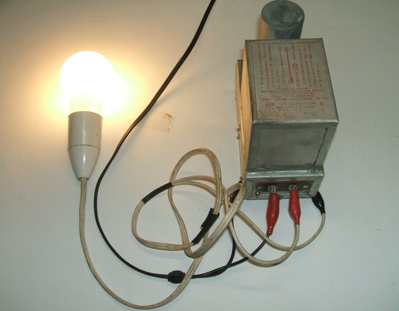
240V 4.5W LED bulb powered from the VP-401. B+ current is 20mA.
Like all the other Vibrapacks tested, this
one was just as well engineered with good quality components. It was no
surprise that it started up without anything having to be done. While it
is for 6V input and would thus suit the Model T Ford, it could also be
used on a 12V supply with zener diodes in the same manner as this
two valve receiver. The suitability of using the Vibrapack in this
way would be dependent on the B+ and heater current draw, however.