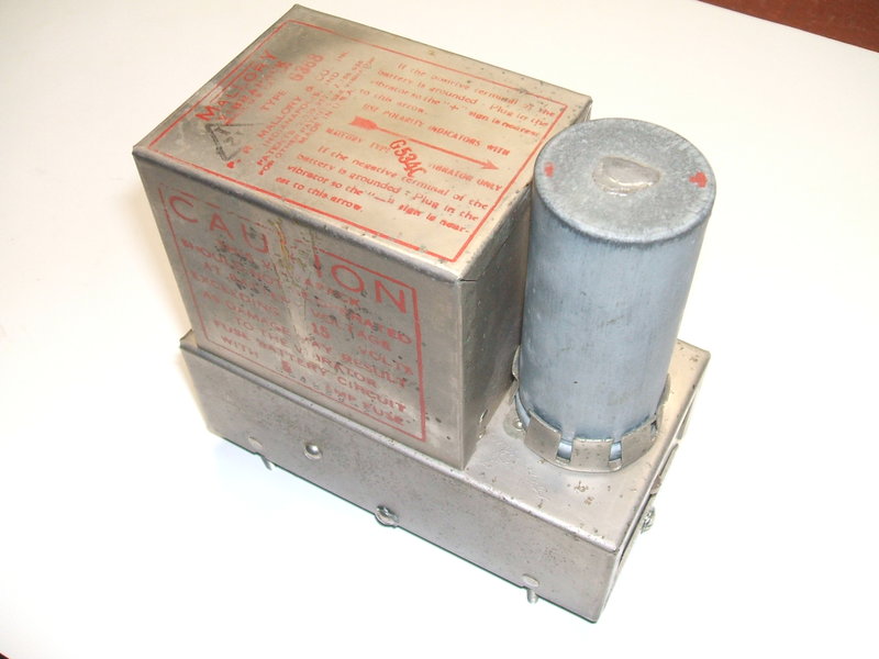
The G368 is unusual as far as Mallory Vibrapacks
are concerned. While Vibrapacks for 12V were not common until the late
1950's, they did exist and are listed in Mallory literature. However, what
is unusual about this Vibrapack is the type number does not follow convention,
nor is it listed in any of the Mallory literature I have. It appears it
has been specially made for a particular manufacturer to order, and Mallory
do make mention of being able to do this.
The usual "consumer" type Vibrapacks are
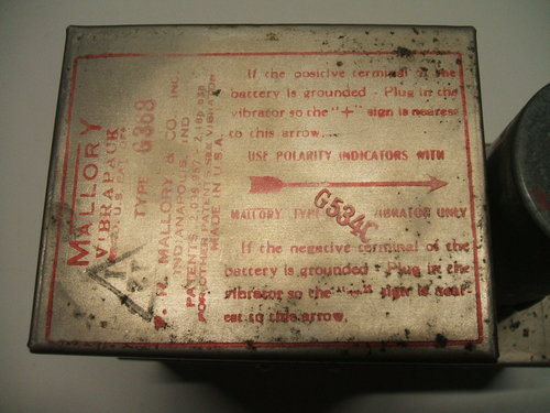
prefixed with VP for 6V, and VPG for 12V. This vibrapack is simply G368.
Whether there was a 368 for 6V is not known.
The G368 is smaller than the 100mA Vibrapacks and the ratings are not actually known, except of course for the 12V input. Comparing the transformer sizes, it would appear the G368 would be rated at no more than 50mA. Output voltage was found to be in the region of 155V. This suggests that with subsequent B+ filtering, and a final voltage of around 140V, this Vibrapack may have been designed for use with battery valves of the octal types rated for 135-180V. However, the 12V input would preclude it for domestic radio use; such sets invariably run from a 6V accumulator. More likely is for a military application. There were numerous portable transceivers using battery valves, and 12V accumulators were not uncommon. The lack of any data in civilian literature also supports this theory. The ebay seller also mentioned military equipment in the ad.
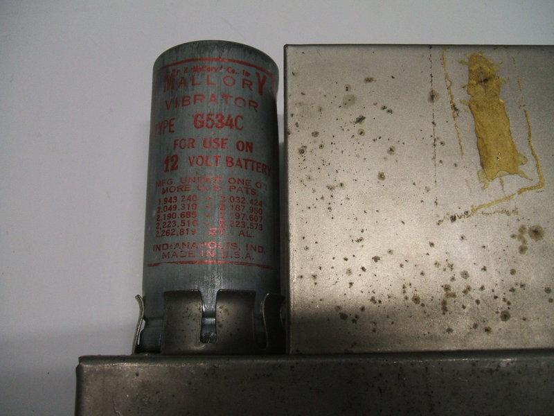
The vibrator is a type G534C. The "G" of course indicating it is the 12V version of the 534C, and "C" indicating a hermetically sealed version of the 534. The vibrator is a synchronous type fitted with a reversible 5 pin base. This allows the Vibrapack to be used with positive or negative earthed 12V supplies simply by reversing the position of the vibrator in its socket by 180 degrees. It is a more elegant method than reversing transformer connections by terminal panels, or having to actually desolder wires to swap over connections. Of course, vibrator power supplies using valve or solid state rectifiers do not care about input polarity, as this is automatically taken care of by the rectifier. The reversible base has been described in more detail here.
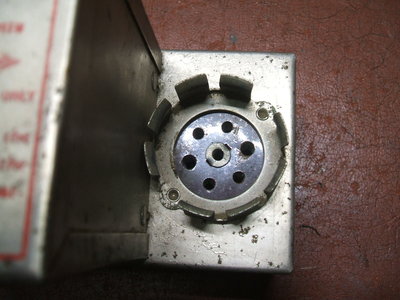
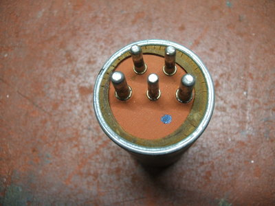
Note the symmetrical socket holes which all the vibrator to be inserted
in one of two ways.
With no information, it is hard to date
the G368. The use of bathtub capacitors and cloth covered transformer wires
could take it back to 1937 when the Vibrapacks were first announced, but
my earliest Mallory catalog from 1945 does not list the G534C vibrator.
It is however, listed in the Radiart catalog
for the same year. My next catalog is from Mallory in 1957 which finally
does show the G534C. As expected, it lists the equivalents as G1801 and
G725.
It is curious why the 534 came into existence
when the 725 was already available since the first Vibrapacks. One gets
the impression the 534 was rather obscure - even by its own manufacturer!
The obscure G534C.
Condition of the G368 Vibrapack was excellent
and quite possibly it had never been used. The earth tag had never been
soldered to. The vibrator was fitted with a rubber sealing ring at the
base which I've not seen on other Mallory hermetically sealed types. Given
its present condition, it's doubtful that the vibrator is still sealed.
This is not important except at high altitude (e.g. for aircraft use),
where contact arcing can be problematic with low air pressure.
The Circuit.
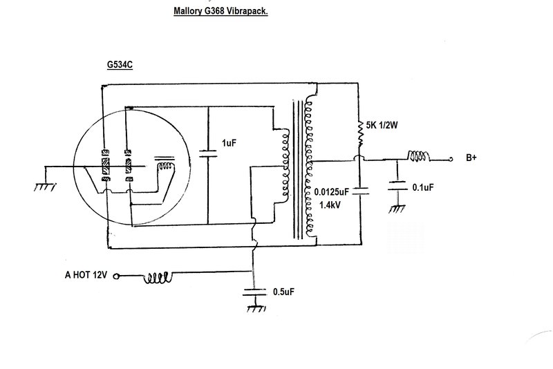
The design is completely conventional,
based around a synchronous vibrator, type G534C. The extra current which
would be required by the heater of a valve rectifier is eliminated thus.
Input is 12V and feeds the power transformer
centre tap via a filter consisting of a choke and 0.5uF capacitor. This
prevents any RFI from being radiated by the battery leads. The G534 vibrator
is a shunt drive design, as are most Mallory types, and so the drive coil
is connected between one of the primary contacts and earth.
Mallory was of the opinion that for vibrator
supplies operating at 12V or above, there should be some timing capacitance
across the transformer primary. Indeed, here we see 1uF of primary capacitance.
In fact, the ideal vibrator power supply has all the timing capacitance
in the primary circuit, but practical realities (especially for the time)
prevented this. The capacitance required is too physically large. For example,
a typical value might be 12uF. Because of the alternating current the capacitor
has to carry, electrolytic types are unsuitable. That leaves paper types.
One of such a high value of capacitance would take up about a third of
the room in the radio!
It is for this reason that timing capacitance
is mostly connected across the secondary, since the capacitance value is
reduced by the square of the turns ratio. The catch is that when connected
across the secondary, the capacitor has to be rated for much higher voltage.
Also, the design of the transformer affects how well the capacitance is
seen by the primary circuit. By placing as much of the capacitance in the
primary circuit as possible, the coupling characteristic becomes less critical.
In the G368 the secondary capacitance is 0.0125uF 1400V.
In series with the buffer capacitance is a 5K resistor to damp oscillations caused by transformer leakage inductance. The B+ is filtered for RF by the 0.1uF and associated RF choke. Further filtering to smooth the DC is required externally to the Vibrapack. This would consist of the usual dual filter electrolytic, and choke or resistor.
Unlike other Vibrapacks, there are no resistors across the primary contacts.
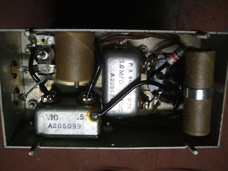
Under the chassis.
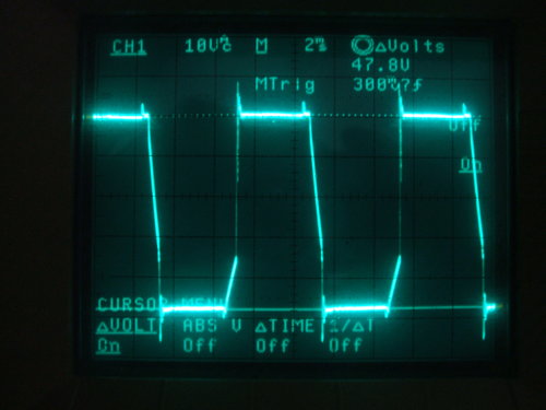
Primary voltage waveform.
The original paper timing capacitor was
left in place for the tests. Experience has shown a Mallory product in
this location is fairly reliable, and there were no signs of excessive
leakage. If the Vibrapack was to be put into use, it would be important
to replace it with a high voltage ceramic, polypropylene, or polyester
type. The two bathtub capacitors should be reliable, with the possible
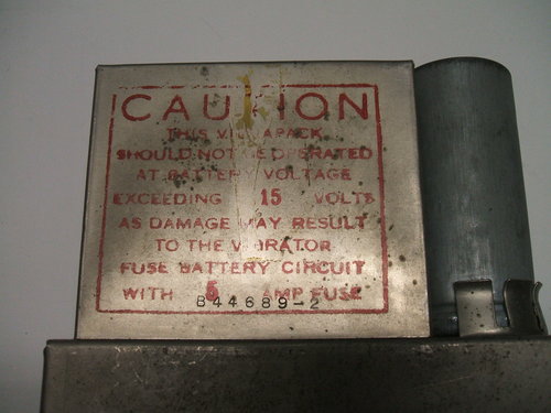
exception of the 0.1uF B+ filter. Fusing must be provided externally, and
a 5A type is recommended.
| Input current @ 12V | Output V | Output mA |
| 500mA | 158 | 15 |
| 550mA | 155 | 25 |
| 625mA | 153 | 35 |
| 950mA | 149 | 50 |
The Vibrapack was tested with a load rheostat across the output, along with a 33uF electrolytic for DC smoothing. Performance is excellent as the measurements show. Until any specifications come forth, it would be wise to keep to a 40mA maximum output current. While the vibrator could easily handle more than this, the transformer windings may not.
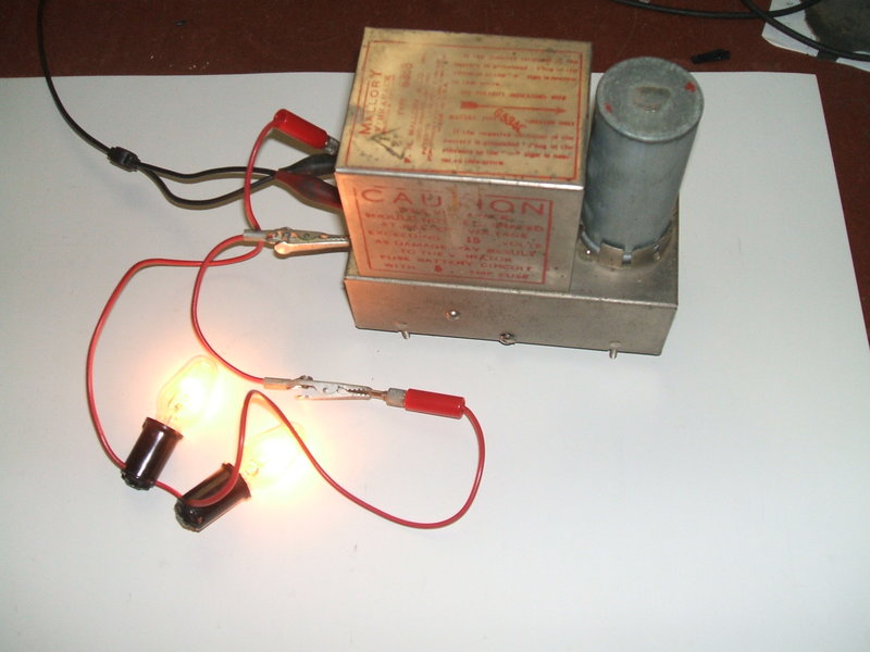
Load is two 117V 7W bulbs in series which draw 45mA at 150V.
So what could it be used for? Obviously,
various battery valve circuits would be in order, but care would have to
be taken if the 12V accumulator was being charged while the apparatus was
operating, due to the more fragile qualities of the battery valve filaments.
Circuits using mains type valves would
be suitable provided the B+ current was low enough. For example, various
one or two valve receivers would suit this Vibrapack quite well.
Update 30/01/2023: Thanks
to a very helpful reader in the U.S, Craig from North Carolina, the mystery
of this Vibrapack has been solved. It was made for an intercom amplifier
used for divers, made by the Guided Radio Corporation in WW2. The model
is 957.
According to the circuit diagram, the
output of the G368 Vibrapack is 108V at 100mA. Contrary to what I had assumed
previously, the Vibrapack powers mains type valves; in particular four
7A5's in parallel push-pull. Hence, the 100mA rating.