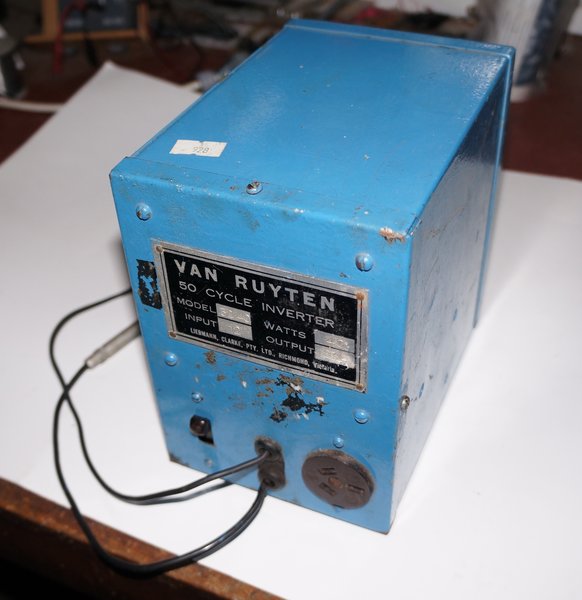
This inverter came from eBay at a very reasonable 'buy it now' price. With it came a quantity of what were called "vibrations bulbs" and a couple of other miscellaneous parts. I had gathered from the photos that there was some kind of fault, and someone had attempted to repair it. Input is 12V, and output is 230V 40W at 50 cycles.
It is typical of Australian made vibrator inverters from the era, using a 50 cycle Van Ruyten vibrator. Smaller inverters used radio type vibrators operating at 100c/s, and several of these have been described elsewhere on the site. Van Ruyten inverters have been described elsewhere on this site; here and here.
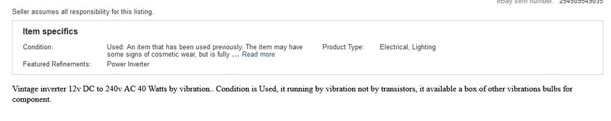
This note stuck to the side implied problems. "A vibrator out of
an old mantel radio" is actually not directly suitable. I hope the "230W"
is a mistake; it should be "230V" of course.
The inverter arrived soon enough, and there
were a few interesting things that caught my attention.
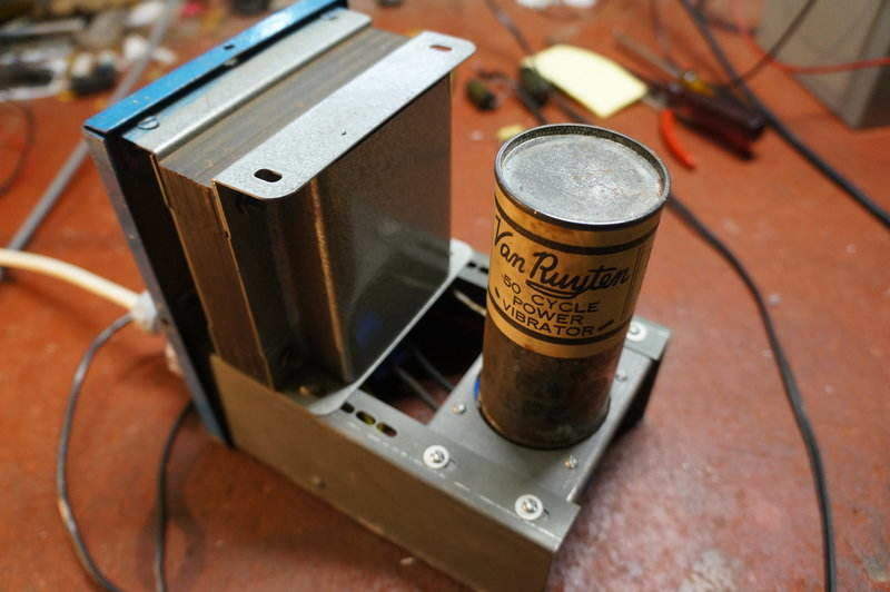
Construction of this inverter is exactly
the same as previous models I've worked on. A chassis made up of various
brackets supports the vibrator and transformer. Depending on the model,
different size transformers can be accommodated without any chassis modification.
The vibrators are always the Van Ruyten
UY-5 pin base type, which are available in 12, 32, and 110V. A Ring Grip
domestic light switch mechanism and three pin output socket are also used
in all the models. In the 100W models, a high/low output switch is provided.
In the 40W model this is not required, and the same hole is used for a
separate grommet for one of the power input leads.
First Impressions.
The cabinet had been repainted blue, and
it seems underneath this was a coat of black. This was over the original
grey hammertone. There had also been three holes drilled into the side
of the cabinet, possibly to mount the inverter on something.
The screws holding the front panel to
the cabinet had been replaced with modern Phillips head self tappers. I
found three of the originals loose inside the cabinet.
Written on the vibrator was "Defective
needs repair". Something was rattling around inside it.
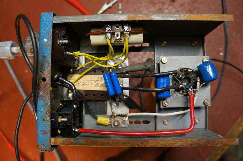
I noticed that one of the capacitors had
been disconnected by cutting one of its leads. The capacitor in question
is a 0.1uF across the driver coil contacts. I dreaded the damage that might
have occurred running the vibrator without it connected. The earthed input
battery lead had obviously been replaced. (As there are no polarised components,
this inverter works with negative or positive earth).
The wire between the switch and vibrator
socket had droplets of liquid on it. I suspect the insulation was decomposing
into something acidic, since there was rust on the casing where the wire
was against it.
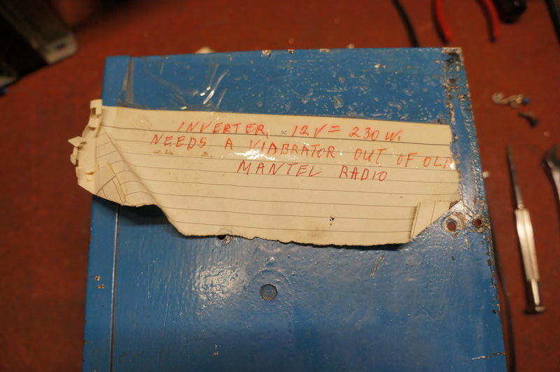
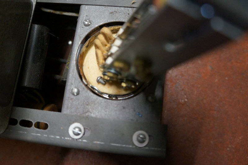
Note the capacitor with lead cut at the vibrator socket. Note also
the droplets on the wire running along the bottom.
As far as the electrical design is concerned
it was as expected, except for one thing. There is absolutely no RF filtering
on the input or output. Not even just one bypass capacitor. Also, despite
the name plate stating 40W output, the hand written labelling on the transformer
states 50W. By the look of the transformer size, I have no doubt it would
easily handle 50W, if not a bit more. The vibrator is rated for at least
100W, so in this inverter it would have an easy life.
The total lack of any filtering implies
this inverter was not meant for any radio or audio equipment. What would
an unfiltered 40W inverter be used for then? A 240V soldering iron comes
to mind, but not much else. I don't think anyone would buy an expensive
inverter just to run a fan, and the inductive nature of such doesn't suit
this inverter anyway. It would tolerate a power factor corrected 20W or
40W fluorescent lamp. This seems to suggest it might be for something specific.
The format of the model number also differs from the other two 100W units
I've worked on.
For Fluorescent Lamps.
The answer to the mystery came from an
advertisement in Radio, Television & Hobbies for April 1959.
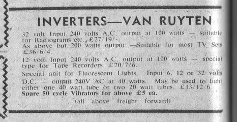
As stated, the inverter can power a 40W
tube or two 20W tubes. A double 20W fluorescent fitting is electrically
equivalent to a single 40W type since the two tubes are connected in series,
with the total voltage drop and running current being the same.
Of course, the inverter does not run the
tubes directly since it has no control gear. Instead, a conventional 240V
fitting is plugged into the inverter, since it contains the ballast, starter,
and power factor correction condenser. On that note, it's essential the
fitting used is of the high power factor type; that is it does have a power
factor correction condenser. Some fittings don't, and will damage the vibrator
since they appear as an inductive load.
The 50W rating of the transformer is also
explained. A 40W fluorescent lamp actually requires about 50W due to ballast
losses.
The extra slots in the chassis allow for larger transformers in
other models.
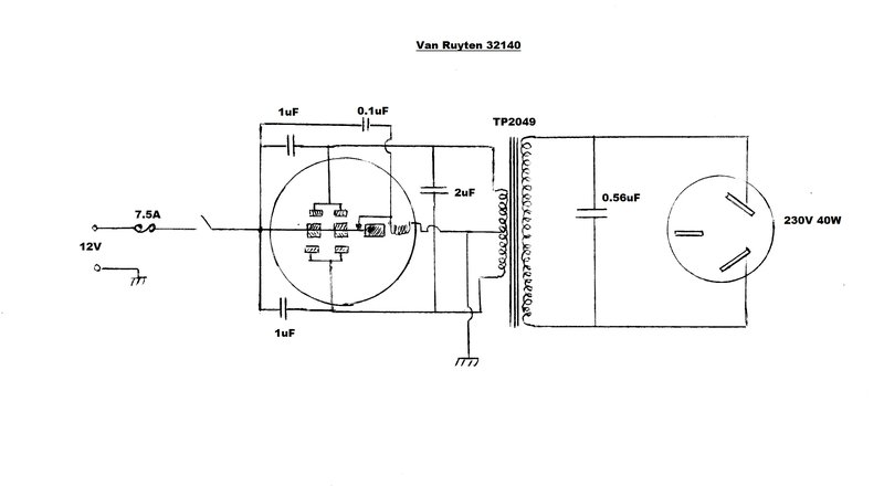
Input fusing for the supply is taken care
of by a 7.5A 3AG fuse. This is located in a bayonet in-line fuse holder
in the active battery lead. Supply is switched with a bakelite tumbler
switch and then fed to the reed of the vibrator. Each set of fixed vibrator
contacts feeds the outside connections of the transformer primary, alternately
switching the 12V between them. The transformer centre-tap is connected
to the earthed side of the supply. This differs from the usual radio type
of supply where the reed is earthed and the centre-tap is fed with the
supply. It's exactly the same in terms of operation of course. The vibrator
drive coil is switched by its own contact. Across this is a 0.1uF capacitor
to prevent sparking caused by the high back EMF, produced when the coil's
magnetic flux suddenly collapses.
There is some primary timing capacitance provided by the 2uF across the whole primary winding, and two 1uF's across the vibrator contacts. The latter appear to be connected more for the specific purpose of assisting with the prevention of contact sparking. Most of the timing capacitance is across the transformer secondary, in the form of a 0.56uF capacitor. Timing capacitance has been discussed at length elsewhere on the site, but briefly its purpose is to control the reversal of voltage in the transformer primary, when the vibrator contacts open. Correctly used, the voltage across the vibrator contacts right at the time when they open and close, will be at a minimum. This prevents contact sparking, as well as contact material transfer. Merely selecting timing capacitance to prevent visible sparking will not always result in the correct value, which also prevents contact material transfer. Thus, the waveform must be observed on a CRO to determine this. In the absence of a CRO, selecting the capacitance on the basis of lowest input current, with the supply operating into no load, is the next best method. However, it is impossible to accurately set for a 65% slope this way. All that can be done is to increase the capacitance slightly from the ideal value, but just how much is the unknown.
The 230V output from the transformer feeds a three pin socket. The earth pin is not connected to anything; not atypical of many inverters. In terms of safety it doesn't need to be, since neither side of the secondary is earthed. However, for inverters powering audio or radio equipment, it can result in a reduction of RFI, where the appliance is fitted with a three core mains lead.
Capacitor Replacement.
First thing was to replace the AEE Microcaps.
These came out in the 1950's and are a paper type. The ones in the inverter
were dated 1966. Although the inverter is only operating from 12V, the
peak voltages are somewhat higher than this, and breakdown can still occur.
Also was the fact that the moulded covering was cracking, and would allow
moisture to enter was not a good sign. I reconnected the yellow Philips
capacitor as I've never seen a failure of this type before, being a very
reliable polyester type.
For the timing capacitor, I'd wait until
checking the value was suitable before replacing it. Experience has shown
that the choice of value used in some inverters has not always been ideal.
Next was to deal with the vibrator before
powering up.
All capacitors replaced.
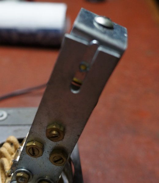
Screw had been removed from driver coil.
It was pretty obvious the vibrator had been got at. The driver coil had been removed at some point and put back incorrectly. The wire to the coil is meant to be routed out through the slot, not on the inside of the mechanism. Also, it was so far down that the reed was jammed up.
What was the point in pushing the coil so far down it hit against
the reed?
One of the contacts was way out of adjustment.
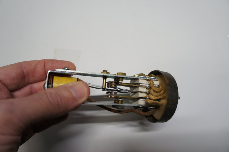
The vibrator is a dual interrupter type, and it was obvious that one contact was not making when its mate on the same side already was. Another thing was the two vertical sections that support the driver coil and its contact were not parallel.
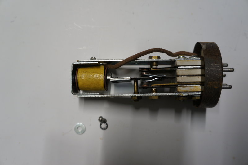
Note that the two sides are not parallel. The drive coil wire should
emerge from the adjustment slot otherwise the reed hits against it.
As far as I could tell, the alignment of
the two sides had come from the factory like that. The stack bolts were
all very tight. This is no surprise as from other examples of these vibrators
I've seen, the quality control was a bit lacking.
However, the driver coil positioning,
and loose lock nuts for all the contact adjustments, is indicative of someone
having a play.
I am never surprised what I see when people
play around with vibrators, not really knowing what they're doing, and
not using any proper adjustment procedure. The fact it was assumed the
vibrator needed to be worked on in the first place is always suspicious.
These Van Ruyten vibrators are series
(separate) drive, and despite the sometimes poor quality control during
manufacture, the contacts are very durable and wear is not normally an
issue. I guess it's the moving parts that always attracts attention!
Our would-be vibrator restorer had replaced
the foam can insulation with paper. The original foam used with these vibrators
has usually decomposed.
The paper was dated from at least 2002.
I used thin foam rubber to replace the
can insulation. The paper would have been satisfactory from an electrical
insulation point of view (the mechanism is live), but foam rubber is better
for acoustic insulation. As per other Van Ruyten vibrators, I used foam
rubber for replacement. At least one manufacturer once used corrugated
cardboard which would be another option.
The paper found inside seemed to mention
something about alternative energy, so it would appear whoever owned this
inverter might have had an interest in such things and was going to use
it with a 12V alternative energy system.
With the vibrator set up visually, it was
time to test the inverter and check the adjustment. Alas, it didn't vibrate.
The reed simply swung over and stayed there, even though the drive contact
was now open. It was obvious why the Philips 0.1uF had been disconnected.
This capacitor had broken down, short
circuiting the driver coil contact. A closer look revealed the voltage
rating was inadequate to start with, at only 160V.
309V across a 160V capacitor. No wonder it broke down.
With a 400V capacitor to replace it, the
vibrator began to work. Measuring the voltage across the capacitor showed
a peak of 309V. Obviously, the designer thought that since the supply was
only 12V, that the lowest voltage rating (160V) would suit. Not so. In
fact, a neon bulb across the driver coil contacts lights up quite brightly,
demonstrating just how much back EMF there is.
Having got that far, it was time to check
the adjustment of the power contacts.
Vibrator in operation. No sparking evident. Drive coil wire was
subsequently re-routed correctly.
Vibrator Adjustment.
For the Van Ruyten vibrators, adjustment
is very easy since it's all done by set screws bearing against the fixed
contacts. I took the easy way out and rather than get out my vibrator
testing panel, I adjusted the vibrator in situ. Disconnecting the timing
capacitor and loading the inverter with a 25W light bulb makes the switching
time more obvious. It must be pointed out this method is satisfactory with
this inverter - it may not be with others. The important point is, the
loading prevents damaging voltages across the vibrator contacts, or across
the transformer insulation. As it was, there was virtually no sparking
at the contacts. The fact it works with no timing capacitor in this situation
does not mean the inverter should normally be used this way. With no load,
destructive voltages do appear. Furthermore, no timing capacitor
will eventually result in material transfer across the contacts, pitting
them and causing them to stick.
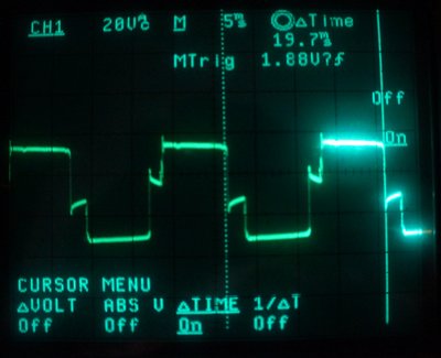
With no timing capacitor, the primary waveform with the inverter
feeding a resistive load looks like this.
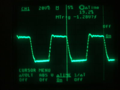
I set the duty cycle to 78%; i.e. 7.8ms
'on' time for each contact, and ensured the 'off' time was fairly equal.
If the duty cycle is not even, there will be a DC component in the transformer
which reduces efficiency. Given that this is a dual interrupter type with
each set of contacts internally paralleled, how does one adjust each set
so they close and open at the same time?
The way to do this is to isolate the other
contact of each pair by having its gap wider than normal. Then the vibrator
is adjusted as normal. Remove the vibrator from the test fixture, and now
visually adjust the 'other' contacts so they appear to open and close with
those previously adjusted. To get a finer adjustment, a current limited
30V 2A bench supply is connected from the reed to each contact pair. By
moving the reed by hand, and causing the contacts to close, a spark will
be visible. The idea is to get adjustment such that the 'other' contacts
spark at the same time as the previously adjusted contact. It's then necessary
to check adjustment with the CRO again and repeat the procedure if necessary.
In this particular inverter, the exact
synchronism of the contacts is not as important as the 100W inverters,
since even if the vibrator was only working on one set of contacts it would
still be well within ratings.
Timing Capacitor.
Originally this was a paper Ducon 0.56uF
600V type. The unloaded waveform showed this value was not grossly excessive,
or too little. Replacing this capacitor with a decade capacitance box,
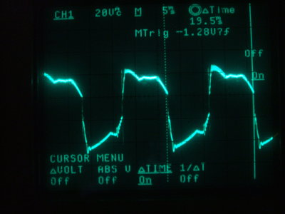
it was found the 'ideal' value was 0.13uF.
Ideal timing capacitance is 0.13uF for this vibrator and transformer.
The 'practical' timing capacitor was about
0.27uF. This is a slightly higher value than the ideal, and is what should
be used in practice to allow for vibrator aging. It's determined so the
slope is about 65%. If the transformer was feeding a rectifier to produce
a DC output, the capacitor value would be left at that.
In the case of an AC inverter, as has
been mentioned many times in the other articles on this site, the timing
capacitor needs to be higher than the ideal or practical values, to accommodate
for the inductive nature of some loads. If an inductive load is used, the
timing capacitance is effectively reduced, which will be damaging for the
transformer and vibrator. It is more of a compromise than a perfect solution,
since with no load the capacitance is more than it should be. However,
in practice, it works well enough without adversely affecting vibrator
life. If the inverter is used with a very inductive load such as a fluorescent
lamp, such as this one, it must be power factor corrected so it appears
resistive. Vibrator inverters do not like inductive loads!
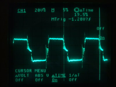
No load waveform with 0.56uF, and at right when loaded with a 40W
light bulb. Note the ringing when loaded.
In this regard, the original value of 0.56uF was satisfactory, and I simply replaced it with a polyester type. There is some ringing in the waveform caused by transformer leakage reactance. This is not abnormal, and can be eliminated by including a damping resistor in series with the timing capacitor. Seeing as this inverter was not intended to provide a perfect waveform for delicate equipment, I did not persevere with this.
| Output Volts | Load | Input Current |
| 227 | 40W | 3.6A |
| 238 | 25W | 2.4A |
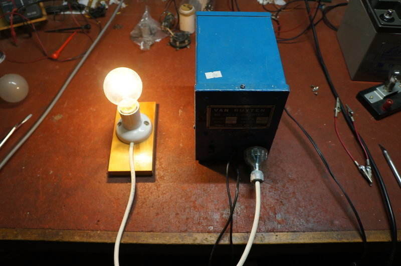
Inverter powering a 40W incandescent bulb.
Driving a Fluorescent Lamp.
 \
\
20W fluorescent lamp powered off the Van Ruyten inverter. 10,000uF
capacitor connected across the 12V input so as not to upset the regulated
power supply being used to power it.
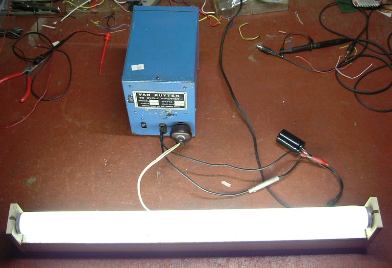
Naturally I had to test the inverter with
a fluorescent lamp. I didn't have a 40W fitting, or high power factor double
20W fitting to hand, so to start with, I tried a conventional 20W fitting
with a glow tube starter. Current draw initially was 6A; this being because
of the power factor correction capacitor and nothing else. Once the tube
started and was drawing current, the consumption fell to 4A. Another 20W
fitting was tried; this one with a filament transformer (i.e. "rapid start").
There was some difficulty starting the lamp unless one side of the 230V
output was earthed. This is not surprising, since rapid start fittings
don't provide a high voltage kick to get the tube started. It must be pointed
out that rapid start fittings are in the minority, and the inverter would
have been designed for switch start types. Current consumption with the
rapid start fitting was about 4A before starting, and stayed at this figure
once started. The waveforms were not checked, but it would appear the filament
transformer provided some cancellation of what would be excess capacitance
until the tube started.
For further info on fluorescent lamp operation,
see the 100W
Van Ruyten inverter article.
The waveforms were not checked, so it
is not known if the power factor correction capacitor was actually the
optimum value in both instances. Efficiency is poor when operating one
20W tube, but would improve with two 20W tubes or a single 40W tube. From
the small amount of information in the advertisement, it does seem to imply
single 20W tube operation was not intended.
When used with a vibrator inverter, it
is important that the lamp starts as quickly as possible, since the timing
capacitance presented to the vibrator is otherwise excessive.
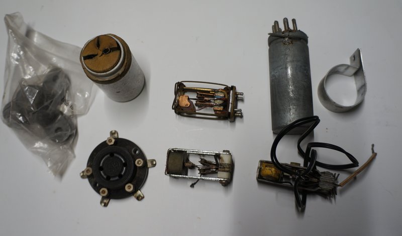
Also supplied with the inverter were these vibrators and other parts.
Considering four other vibrators were included, this certainly made the purchase good value for money. There was a shunt drive synchronous mechanism which I've never seen before, as was a non-synchronous mechanism which I vaguely recognise as a military type. It's quite small and suspended by what are really rubber bands. More familiar is the 12V Oak synchronous or dual-interrupter mechanism. The 'complete' vibrator is a 6V V5211 split reed synchronous. Unfortunately, its driving contact has broken off. One could configure it to operate as shunt drive if necessary. An aluminium clamp was provided which fits the can. Two mystery objects are a home made two pin socket, and two three legged support brackets. Lastly is an ancient surface mount UY-5 base valve socket - which fits the Van Ruyten vibrator. Presumably this was to connect up the VR vibrator for some kind of 'testing'.
It would appear that the owner, convinced
the inverter needed a new vibrator, went in search of such named objects.
Unfortunately, none of them are suitable for direct use in this inverter.
For one thing, only one of them is 12V. Also, the output will be 100 to
115c/s instead of 50c/s, which means the timing capacitance will be much
too high. Also, the current ratings of the contacts will be pushed to above
their limits, with the possible exception of the unmarked 12V Oak mechanism
- if it is dual interrupter and not just synchronous. I have not checked
the contact timing to confirm this.
In summary, it just shows why the apparent
simplicity of a vibrator power supply gets so many into strife. I doubt
the original Van Ruyten vibrator was faulty at all, and it shouldn't have
been tampered with. More likely, it was got at because it wasn't vibrating,
and it took a while to realise it was the shorted 0.1uF instead. Too late
now, because the vibrator had already been put well out of adjustment.