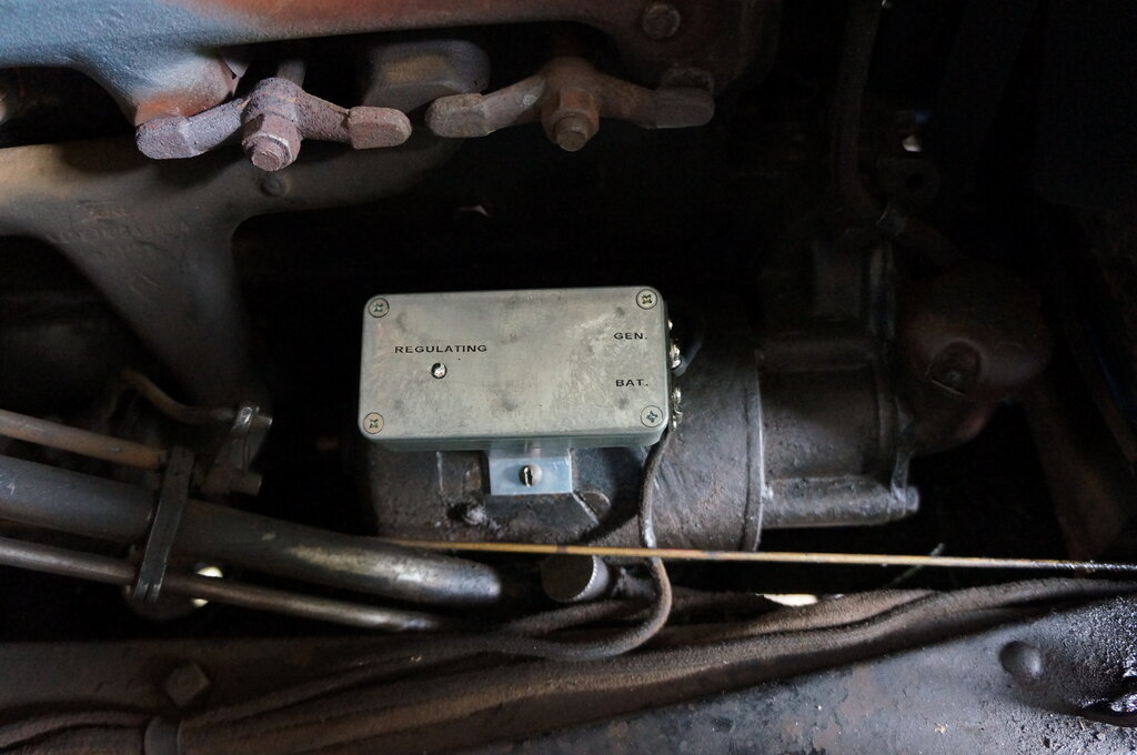
Prototype is housed in a diecast box .
As a background to this article, voltage
regulation for the Model T has been described, along with a commercially
made accessory regulator from Fun Projects, here.
While I had thought of a comparator type
regulator some years ago, it was only recently that work was done to develop
a working unit, since the commercially made unit is no longer produced,
and there is demand for a replacement. This has been discussed on the MTFCA
forum here.
The first outcome of that is the comparator
regulator described here. This article describes an alternative method,
using switchmode regulation.
Further discussion on Model T voltage
regulators in the MTFCA forum can be found by searching for "mtfca voltage
regulator".
Prototype is housed in a diecast box .
Linear, Comparator, and Switchmode
Regulators.
Since the Model T generator has only one
terminal, to which both the armature and field are connected, the only
way to control its output (without modification) is by the shunt method.
One obvious way would be to shunt the
generator output with a power transistor, whose base current is increased
as the generator voltage increases. This could be achieved with a zener
diode between base and collector. See the circuit below.
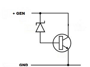
Simple method for linear shunt regulation, but is very inefficient.
Alternatively, a very high power zener
diode could be used on its own instead, if such a device of sufficient
power rating can be found.
Unfortunately, while this linear
approach will prevent battery overcharge, it is extremely inefficient.
Once the battery is fully charged, the generator will continue to produce
its full output - which means it is unnecessarily wearing the commutator,
bearings, and brushes, as well as running hot. And, it is consuming power
from the engine. Aside from that, all the generator output is simply dissipated
as heat in the regulating device.
To put this in perspective, if the generator
current is 5A and the battery voltage is 7V, then the transistor or zener
diode has to dissipate 35W of heat. Those that prefer a 10A charge can
double that figure.
Instead, a voltage comparator can be used as a switch. When the battery voltage reaches 7V, the generator output is short circuited completely. This shuts off the charge current, and also takes the load off the generator. This is because with the armature terminal shorted to earth, the field coil is deprived of supply, and therefore there is no output current. The generator runs cool with minimal mechanical wear. This is the method used for the regulator described here.
An alternative to the comparator method
of regulation is to use pulse width control, as per a switchmode power
supply. This is the method used by the commercially made Fun Projects
unit. Both comparator and switchmode designs operate by terminating the
battery charging at a pre determined voltage; typically around 7 to 7.2V.
At this voltage the battery is fully charged.
In the case of the comparator regulator,
the battery is fed with the full charge current, as set by the generator's
third brush, until 7V is reached. At this point, charge current is stopped
completely. The battery voltage then falls to a lower level, typically
6.8V, and the charge process begins again. The time taken for the battery
voltage to fall depends on the current taken from it, and the time taken
for it to rise depends on the charge current. In practice, the switching
time between the two states may be several seconds or more.
The switchmode regulator has some things in common with the comparator method, but the main difference is the switching speed is much faster; for example 6kHz. Because this frequency is usually fixed, pulse width modulation is used to control the average charge current. When a high charge current is desired, the pulse width (the time which charge current flows) may have a duty cycle of up to 100%. When a low charge current is required, the duty cycle may be zero or only a few percent. For the switchmode charge regulator, the pulse width starts off with a high duty cycle, which is reduced as the battery comes up to 7V. Since the average current reduces as the battery comes up to charge, it can be imagined that it takes longer for this point to be reached, than with the comparator regulator.
Both types will efficiently prevent overcharge. The visible difference to the user is in the behaviour of the ammeter. With the comparator regulator, the charge rate can be clearly seen as the meter deflects between zero and full charge current every few seconds or so. With the switchmode regulator, the meter physically cannot respond to the high switching speed, and nor could the human eye see the movement even if it could, so the meter shows an average reading which appears to operate smoothly in a linear fashion. The meter needle gradually changes from full charge to zero, as the battery comes up to full voltage.
The TL494.
One of the most common, and oldest of
switchmode IC's is the Texas Instruments TL494. Its most popular application
was in computer power supplies during the 1980's-90's. It is still cheap
and widely available today.
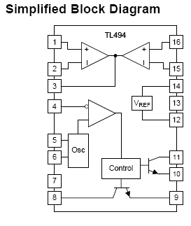
Design Begins.
To explain the following circuits, the
internal functions of the TL494 are shown here:
One of the unknowns was the supply voltage;
specified as 7 to 40V. In actual fact, the TL494 does work below 7V, but
the main effect is a drop in the voltage reference below 6V. Luckily, since
the voltage of a charged battery plus the drop across the cutout diode
is around 7.6V, the TL494 will get enough voltage when regulation is actually
required.
As with the comparator regulator design, the initial bench testing was done with a 12V power supply in series with two paralleled 12V 36W lamps to act as a current source.
The first circuit tried was in its most
basic form, suggested by MTFCA forum member, Luke. The circuit was again
based on the 'grounding switch' whereby a MOSFET is used to short circuit
the generator output to stop the charge current. And, as before, a solid
state diode is used for the cutout, to prevent battery current flowing
back into the generator when its output voltage is less than the battery
(e.g. when the engine is stopped). The cutout also prevents the regulator
short circuiting the battery when the MOSFET switches on.
The longer the the MOSFET conducts, the
lower the average charge current. Provided the MOSFET is switched fully
on or fully off, power dissipation is minimal.
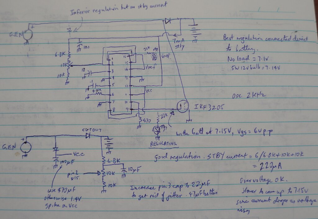
Notes from first circuit.
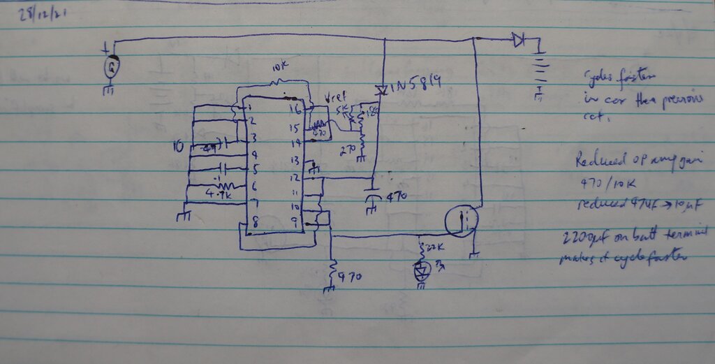
The oscillation frequency was set by the .1uF and 4.7k at pins 5 and 6, to 2kHz. Although not actually required, the two error amplifiers were connected in parallel; pin 1 and 16 being the non inverting inputs, and 2 and 15 being the inverting inputs. Common output is at pin 3 which controls the pulse width. The intention is that for 'normal' use, one error amplifier is for voltage control, and the other for current control.
The error amplifier was connected in the
usual way; i.e. an adjustable voltage divider connected across the battery,
with a 6.8k, 10k trimpot, and 10k to earth. Voltage reference was the 5V
provided at pin 14 for this purpose. If the voltage at pin 2 rises above
5V, the pulse width increases, short circuiting the generator for a longer
period of time.
The value of voltage divider resistors
is high enough not to cause any significant battery drain when the car
is not in use.
There are two transistor outputs in the
TL494. Depending on the configuration of pin 13, these can be used as a
push-pull output (when driving a centre tapped transformer), or with both
transistors operating in phase for single ended output. Since we're driving
a single MOSFET here, the single ended mode is used. In this configuration,
the output transistors are connected in parallel as emitter followers.
The load resistor is 470R to earth, and
the emitters drive the MOSFET gate directly. As before, the MOSFET must
be one which fully saturates with a gate voltage of 4V or less. This is
because the TL494 supply might be as low as 6V, and some voltage is lost
across the output transistors in emitter follower mode.
As a diagnostic feature, a high brightness
LED was also connected to the output so that it could be seen when the
MOSFET was being driven (and the circuit was regulating).
To eliminate jitter and provide stability
to the pulse width, a 10uF was connected to pin 3, the error amplifier
output.
As drawn above, the circuit seemed to
work on the bench satisfactorily. However, to make it practical, there
was the question of standby current. This was found to be rather high at
7mA. So, the next thing was to power the TL494 from the generator alone.
This was done with a 1N5819 Schottky diode and 470uF capacitor.
To eliminate standby current completely,
the error amplifier voltage divider was then connected to the 470uF capacitor,
since in theory this would follow the battery voltage. In practice, the
regulation was notably inferior, so the circuit was returned to original.
Spike filtering from the battery was more
effective when the bottom end of the 6.8k was bypassed, rather than the
actual battery supply. This also allowed a smaller capacitor; 100uF > 10uF.
At some points during the regulation it was found that there was jitter
on the pulse width, so the pin 3 capacitor was increased to 47uF to improve
this.
With the circuit working well on the bench, it was assembled on Veroboard, and mounted in a diecast alloy box.
In Car Test - Failure.
Unfortunately, testing it in the car was
not successful. There was a very strange low frequency cycling of the pulse
width. This varied with engine speed. Looking at the ammeter, one would
think it was actually a comparator circuit! And so began many hours of
experimentation.
Thoughts were as to whether it was ignition
interference or some kind of peculiar characteristic of the generator.
Touching capacitors to all active points on the circuit didn't achieve
anything, although 10,000uF connected to the battery terminal of the regulator
did speed up the cycling.
Generator Test.
The main difference between the bench
set up is that a regulated 12V power supply was being used, with a pair
of 12V 36W lamps to provide current limiting. Perhaps the generator voltage
was slow to come up because of it being self excited. This was tested,
with a 12V lamp connected to the generator.
Ignition or Power Supply?
What about ignition interference? Given
the high value of voltage divider resistors, maybe ignition interference
was getting into the error amplifier. Perhaps if we took the inputs as
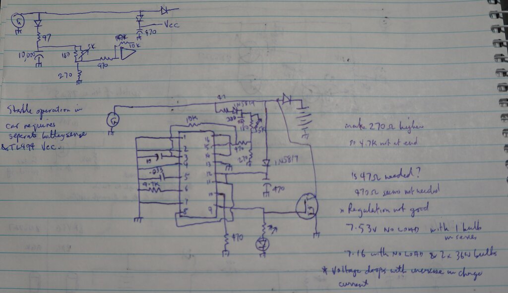
close to earth as possible, it might reduce this. Indeed, it was noted
that the Fun Projects regulator used 240 and 100 ohm resistors for this
purpose. So, the circuit was modified with 180 and 270 ohm resistors. A
5k trimpot allowed fine adjustment. Now that the bleed current was too
high to leave across the battery, the voltage divider was again powered
from the generator supply. Additionally, one of the error amplifiers was
taken out of circuit, since it did not contribute anything, but could potentially
be a source of ignition interference getting into the circuit.
The 10k and 470R at pin 15 were later added to reduce the error
amplifier gain.
This did not make any improvement. At this point I was trying to think of other things which could cause the strange cycling. Perhaps the error amplifier gain was too high and the circuit was over correcting. I noted that the example circuit in TI's application notes had negative feedback applied to the error amplifier. I tried the same, but the only difference now was the cycling was faster. Thinking the capacitor at pin 3 could be part of this long time constant, I reduced it to 10uF, but with no useful effect. Another unknown was the switching frequency. Perhaps the inductance of the generator was causing the strange time constant. To test this theory, the switching frequency was raised to 6kHz by changing the .1uF at pin 5 to .033uF. This did not improve anything.
We're getting somewhere...
To find out if it was the generator supply
to the TL494, and / or the voltage divider, the unit was left on the car
and an external power supply connected instead to the input of the 1N5819
diode. The engine was started, and with the power supply around 7V, the
waveform was at last stable. This eliminated the ignition system.
Next, the 1N5819 was connected back to
the generator, but with only the voltage divider connected to the power
supply. Again, the waveform was perfectly stable. This test indicated that
the TL494 was happy with its Vcc coming from the generator.
This narrowed down the problem to the
error amplifier. So why wouldn't it work off the battery voltage, but was
fine with the power supply? With a set of clip leads, the voltage divider
input was connected to the generator through a separate diode and 47R resistor.
This was bypassed with 10,000uF. And it worked - a completely stable waveform
without the low frequency cycling.
Further investigation found that the 10,000uF didn't have to be that high at all, and neither did the 47R need to be present. What the circuit was objecting to was a common Vcc and voltage divider input. It wanted both fed from separate diodes. The 10,000uF was reduced to 220uF without much ill effect. It seemed there was some kind of feedback when Vcc was shared with the error amplifier input, and the separate diodes provided sufficient isolation.
Unfortunately, while testing on the bench it was found the regulation was not working as it should. The battery voltage actually increased if the charge current was decreased! As the notes above show, with one series bulb (1.5A), the no load battery voltage was 7.53V, but with two bulbs (3A) it was 7.16V.
Voltage Reference.
At this point, I decided to bench test
the Fun Projects regulator again. Since it measures battery voltage on
the generator side of the cutout, I wanted to see how good its regulation
really was. It was in fact quite good, varying from 7.19V unloaded with
1.5A charge, to 7.3V with 3A charge.
One thing about the FP regulator is the
IC it uses; assumed to be an LM3524D. The more common SG3524 cannot be
used directly because of an important characteristic. I was beginning to
wonder if the TL494 had the same limitation.
The characteristic in question is the
common mode input voltage for the error amplifier. With all three IC's,
the internal voltage reference is 5V. The SG3524 has a common mode input
voltage of 1.8 to 3.4V, which prevents the 5V reference being used directly.
The LM3524D has a common mode input voltage of 5.5V (which means the 5V
reference can be used without dividing it down), and the TL494 is Vcc-2V.
Since the TL494 is operating in this circuit
with a Vcc of about 6V, the problem becomes apparent. Vref is 5V at pin
14. But, the common mode input is limited to 6 - 2 = 4V. No wonder the
error amplifier can't work properly. It's being fed more voltage than it
can work with. The way around this, as shown in the application notes,
is to divide down the Vref; they used 2.5V for a 5V supply.
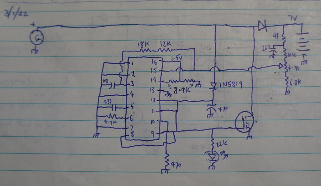
And this is when things began to start
working. I used two 3.9K resistors to provide a 2.5V voltage reference;
well under the 4V limit.
I also returned the error amplifier voltage
divider resistors to their higher values, since connection across the battery
is more accurate for voltage sensing.
Feedback.
It regulated well on the bench, but not
so good in the car. It was better though, in that the cycling was now not
always present. Time to investigate the error amplifier gain. With no feedback
resistor, it cycled. With a randomly chosen 12k it was stable at last.
No doubt there is some complicated mathematical formula for calculating
the gain required, but it was much easier to experiment. It continued to
work well with 18k added to the 12k; i.e. 40k.
It's working at last!
Now for some final tidying up. Since the
circuit was now stable, the feedback resistor was replaced with 56k without
any instability.
Around this time I had found TI's article
on designing circuits with the TL494, and learned a little more about pin
3. They said that capacitive loading here is undesirable. It seems that
error amplifier stability is supposed to be obtained by keeping the gain
low. So, I removed the 10uF at pin 3. The circuit still worked, although
there was some jitter on the waveform.
It occurred to me that this could be eliminated
by bypassing the input from the battery sense voltage divider. If the error
input had no jitter, and the voltage reference didn't either, then there
should be none in the output. Indeed, 10uF bypassing the 10k at the top
end of the trimpot restored complete stability. This also allowed the removal
of the 47R and 220uF.
In Car Success.
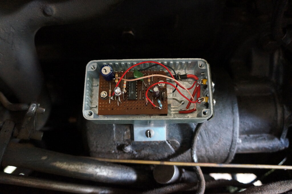
Circuit assembled on Veroboard.
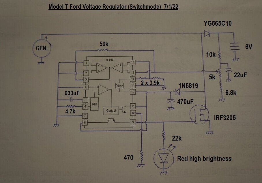
| Pin | Description |
| 1 + I/P to error amp 1. | Earthed - error amp not used. |
| 2 - I/P to error amp 1. | Earthed - error amp not used. |
| 3 Error amp output. | Controls gain via 56k. |
| 4 Dead time control. | Dead time control. Not used. |
| 5 Timing capacitor. | Timing capacitor (.033uF). |
| 6 Timing resistor. | Timing resistor (4.7k). |
| 7 Earth. | Earth. |
| 8 Collector of O/P transistor 1. | Connected to Vcc to work as emitter follower. |
| 9 Emitter of O/P transistor 1. | MOSFET gate drive. |
| 10 Emitter of O/P transistor 2 | MOSFET gate drive. |
| 11 Collector of O/P transistor 2. | Connected to Vcc to work as emitter follower. |
| 12 Vcc. | Supply voltage for IC. |
| 13 Output configuration. | Earthed for single ended O/P. |
| 14 Vref. 5V. | Divided to 2.5V via 2 x 3.9k |
| 15 - I/P to error amp 2. | Fed from battery sense voltage divider. |
| 16 + I/P to error amp 2. | Fed with 2.5V reference. |
Constructional Notes.
Most of the component values are not actually
critical.