The Fun Projects Voltage
Regulator
It is a known limitation that the Model
T Ford can suffer from an overcharged battery because of the absence of
any voltage regulation. While the 3rd brush generator allows one to set
the charge current, which remains fairly constant over a wide generator
speed, there is nothing to reduce the charge when the battery is full.
So, if one has set the charge current to say 10A in order to run the headlights
continuously, when the headlights are off the battery will receive this
10A, even after it is fully charged. That's not good for the battery, apart
from it losing more electrolyte than normal. In practice, the best compromise
with the stock standard set up is to set the charge current to 5A which
won't damage the battery, and will allow moderate headlight usage.
Principles of Automotive
Voltage Regulators.
The principles of voltage regulation for
automotive electrical systems were known back in the 1920's, but Ford with
its economy focussed ideals, ignored it.
The method used, which has remained to
the present time, is to reduce the generator (or alternator) field current
when the battery has reached full charge.
Until solid state regulators started to
become common in the 1970's, the regulator was an electromechanical device
built along the lines of a relay. One set of relay contacts was placed
in series with the field coil supply. Shunted across the contacts was a
resistor; the purpose of which set the minimum field current and also protected
the contacts against the arcing that would result from the rapidly collapsing
magnetic field of the field winding.
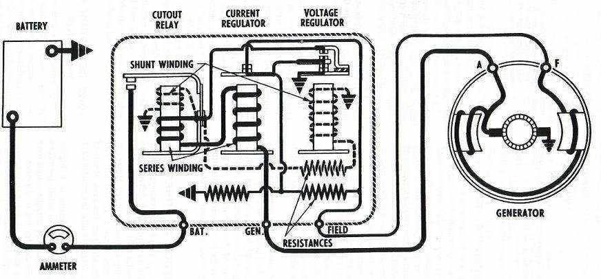
This set of contacts was pulled in by
the voltage coil. Effectively, the voltage coil is connected across the
battery and its pull in power is obviously dependent on battery voltage.
Therefore, the contacts are set to open when the battery has reached about
7V for a 6V system, or 14V for a 12V system.
The charge current is severely reduced,
and the battery does not overcharge. Along with the voltage coil and contacts,
are also a current coil and cutout with their own sets of contacts. The
current coil senses battery charge current and its contacts open, again
reducing field coil current, if the charge current is too high - such as
when the battery has a low charge. This is required to protect; a) the
battery, b) the generator brushes and commutator, and c) the generator
windings from excessive current. Finally, the cutout coil senses current
direction. Its contacts are between the generator output and battery. If
current flows from the generator to the battery the contacts close, and
if the current from the battery tries to flow back into the generator (e.g.,
when the engine is stopped) then the contacts open. This prevents the battery
discharging into the generator when the car is not in use.
The design of alternators is such that
they are inherently current limited, by means of winding inductance and
that they generate AC. The rectifier diodes used to change the three phase
AC to DC automatically prevent the battery discharging when there's no
output. Hence, alternators do not require the cutout and current coils
in the regulator assembly.
Electronic regulators which replaced the
earlier mechanical types use a power transistor to control the field current.
This is controlled by a zener diode voltage reference and comparator circuit.
As alternators were standard by this time, there was no need to provide
current control or a cutout in the electronic regulator assembly.
Regulation and the
Model T.
Third brush generator charging system.
Until 1939, Ford used a third brush generator.
Current regulation is adjusted by the setting of the 3rd brush. In simple
terms, this setting adjusts how much current flows in the field coils.
The voltage is not regulated, being held only within safe limits by the
loading of the battery.
In essence, a third brush generator is
a constant current source. A disadvantage with this set up is that once
the battery is fully charged, it still receives full charging current.
Setting the charge current is very much a compromise. It should not be
so high to boil the battery electrolyte, but enough to replace the current
taken by the electrical loads of the car. In practice, 5A has been found
to be quite suitable.
Battery and generator life can be extended
by including voltage regulation, since charge current decreases when the
battery reaches full charge. In so doing, the mechanical drag and brush
wear on the generator is also reduced.
An immediate problem trying to connect
an accessory voltage regulator to the Model T, or any other car using a
3rd brush generator, is that there is only one terminal on the generator,
which is for the output.
Since the field winding is energised internally,
it has no external connection. To use a standard regulator involves having
to separate the field coil connection, and providing a second insulated
terminal. Indeed, this has been done. However, it looks out of place and
involves wiring modifications. For those who just want a drop in regulator
with no wiring modifications, an electronic regulator was developed by
Fun Projects.
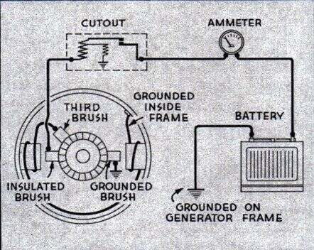
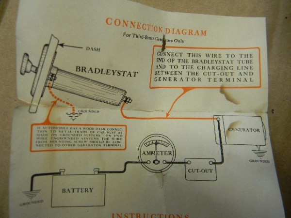
First Principles - Grounding Switch.
Switch short circuits generator output when no output is desired.
Well known in the Model T world is the
so called "Grounding Switch". It made its appearance in an issue of "Tinkering
Tips" many years ago. By means of this switch the generator could be shut
off, if it was felt the battery did not require further charging. It was
also thought that by shutting off the generator, some extra horsepower
could be obtained from the engine. However, a theoretical analysis of the
latter tends to make this claim suspicious. Assuming a charge current of
5A at 7V, that is a power of 35W. Assuming 50% efficiency for the generator,
the input power would be around 70W. That is about one tenth of one horsepower!
(1 HP = 746W).
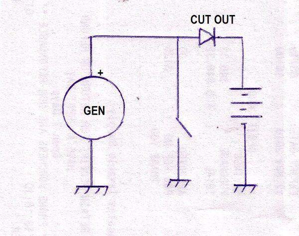
To shut off the generator, we cannot merely
open circuit the connection between the generator and battery, because
it is a constant current source, meaning the output voltage will rise to
a destructive level under no load, which can burn out the windings. But,
because the generator is a constant current source, we can short circuit
the output. Taking the output terminal to earth immediately robs the field
coil of supply. It is perfectly safe to run the generator continuously
this way, because since the field coil is not energised, the armature cannot
produce any output.
Shorting the generator output to earth
would cause a huge current from the battery to flow if it wasn't for the
cutout; shown as a diode in the above diagram. The diode merely becomes
reverse biassed when the switch is closed, and thus no current from the
battery flows to earth. Importantly, when a grounding switch is installed,
the cutout must be a diode type. This is because a mechanical cutout
makes a direct connection to the battery when activated, and the switch
would be shorting the battery current, limited only by the wiring resistance,
until the cutout opened. Obviously, the switch and cut-out will not last
long used like this. It is true that the switch could be closed prior to
the engine coming up to full speed, before the cutout closes, but human
nature being what it is, would eventually result in this point being forgotten.
Another method of controlling the charge
rate is to simply divert more or less of the generator output to earth,
as done by this period accessory:
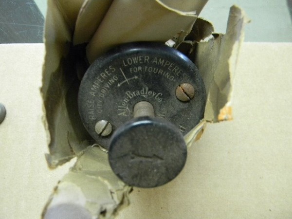
(Photos courtesy MTFCA forum).
Here, a high power variable resistor is
used to shunt the generator output. For example, assume the third brush
is set to 10A. If the shunt resistor is set to draw 4A, then the battery
will be charged at 6A. The resistor appears to be a carbon pile type. This
is
a tube filled with carbon discs (hence
the term "pile"). If the pressure against the discs is increased, they
are pressed more firmly together, and the resistance drops. In this case,
the adjustment is made by a screw threaded plunger.
While this method no doubt can save the
battery from being overcharged, it is very inefficient, with all the diverted
current going up as heat. Additionally, the generator output is not actually
reduced. The input power from the engine remains the same, as does the
rate of wear on the generator. However, unlike the grounding switch, this
one can be used with a mechanical regulator.
Principle of Regulation.
Having acquainted ourselves with the grounding
switch, we can see that if the switch was closed when the battery voltage
increased to 7V, and was opened when it fell below this, the battery would
remain fully charged without risk of overcharge. The concept of the regulator
is to do this automatically.
To take the generator output to earth,
either a power transistor or a MOSFET could be used. To control this,
a switchmode controller or a comparator could be used. A switchmode control
would gradually increase its 'on ' time (i.e. earthing the generator) as
the battery reached 7V, and give the appearance of a variable current control
when observed on the ammeter. A comparator would provide full charge until
7V was reached then shut the charge off altogether, until the battery voltage
dropped to say 6.5V. This would show more of a pulsing type of indication
on the ammeter.
Note that the charge current is still
determined by the 3rd brush setting.
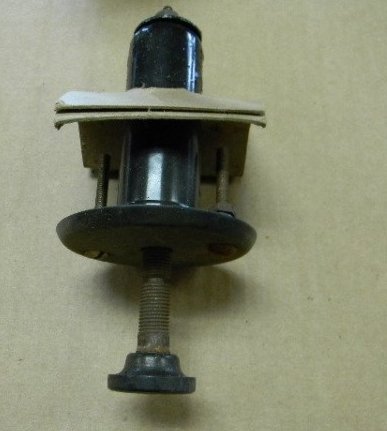
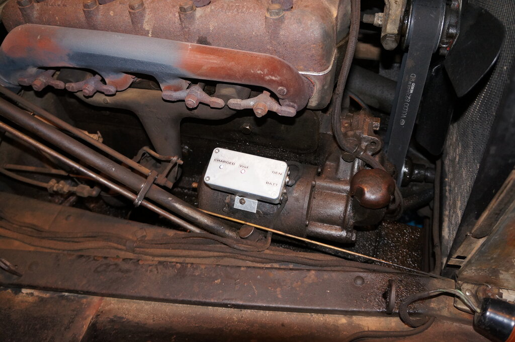
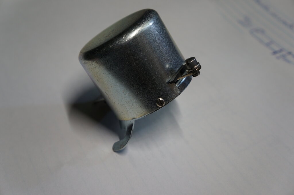
The Fun Projects Design.
A well known and popular accessory for
the Model T is the Fun Projects Voltage regulator. It was available from
various Model T parts suppliers. It eliminates the potentially unreliable
mechanical cutout, and prevents battery overcharge. It is a drop in replacement
for the original cutout, looks identical, and needs no additional wiring.
A further advantage is the crowbar protection to prevent generator burn
out, if the battery should be disconnected.
However, there is no technical information
available on how it works, or the internal design. As I'm often asked about
the Model T electrical system, it was necessary to investigate and provide
my own information.
The particular regulator in my possession
was given to me on the premise that it was faulty, and could I fix it?
As I discovered, the regulator was actually quite OK, but other wiring
in the car was at fault. Nevertheless, I had been curious about the design
and wanted to confirm my theory as to how it worked. So what better way
than to examine the unit, and trace out the circuit. It could be of use
for others who have a faulty regulator, or just want to build their own.
Opening the unit simply involved a slight grind into a couple of spot welds.
The cover then slips off.
I used a variable, current limited power
supply, in series with the secondary winding of a 14V power transformer
(primary not connected), to test the unit, which indicated it was functional.
Upon raising the input voltage, a high frequency tone could be heard from
the power supply, and connecting a CRO showed that indeed it was rapidly
switching on and off.
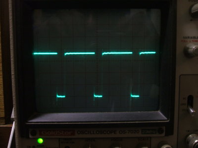
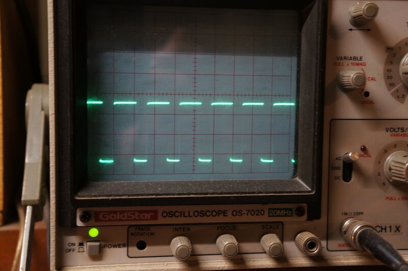
Waveform at generator terminal. As battery voltage rises, the pulse
width shown here decreases so that the generator output is earthed for
a longer period. Frequency is about 6kHz.
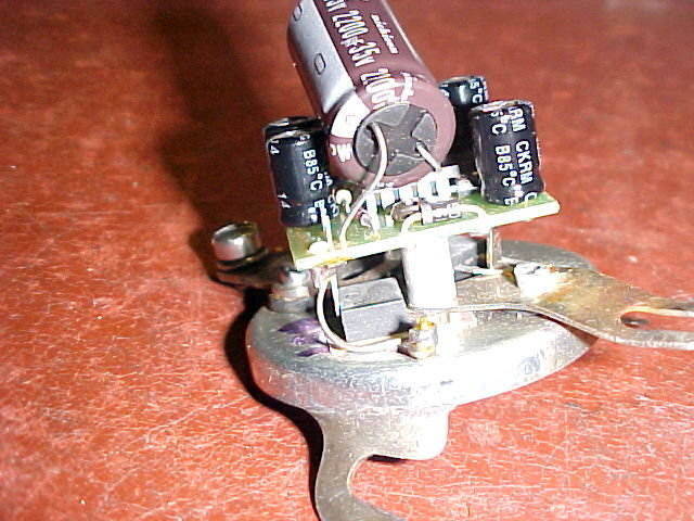
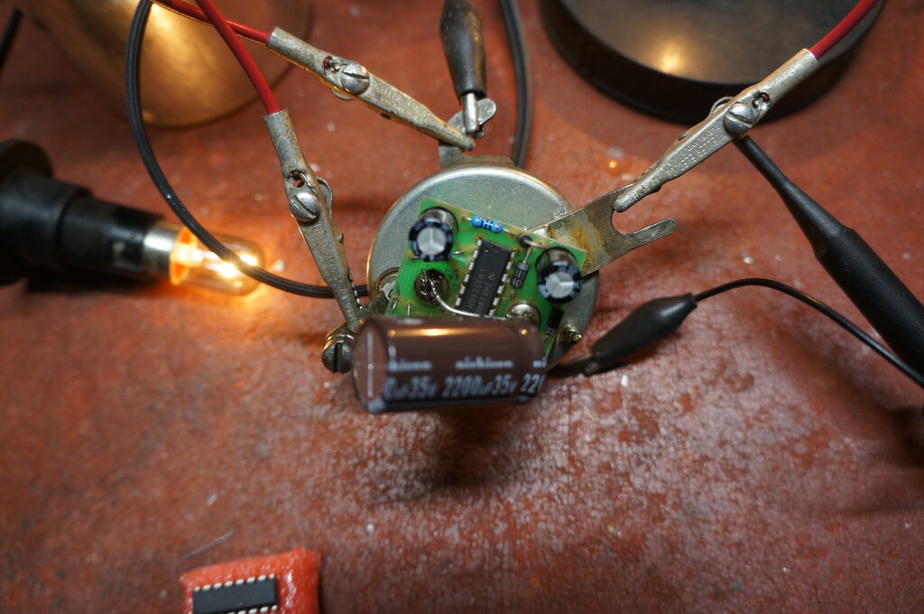
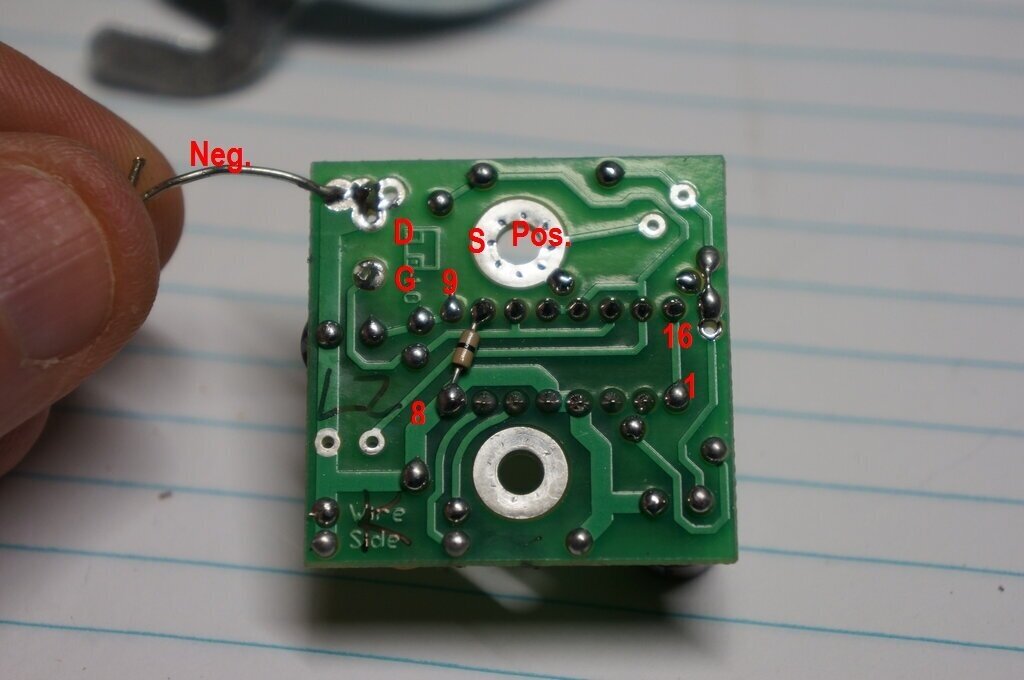
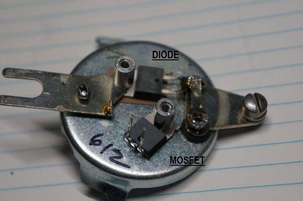
Inside the unit, the cutout diode and switching
device (both TO220 packages) are mounted on the chassis, the diode between
the generator and battery terminals, and the switching device between the
generator terminal and earth. This immediately confirmed the regulator
is based on the well known 'grounding switch'. Mounted above, is the PCB
with the other components, including a 16 pin IC. Remarkably, the IC,
diode, and switching device were devoid of type numbers. Thankfully, that
need not present a serious obstacle.
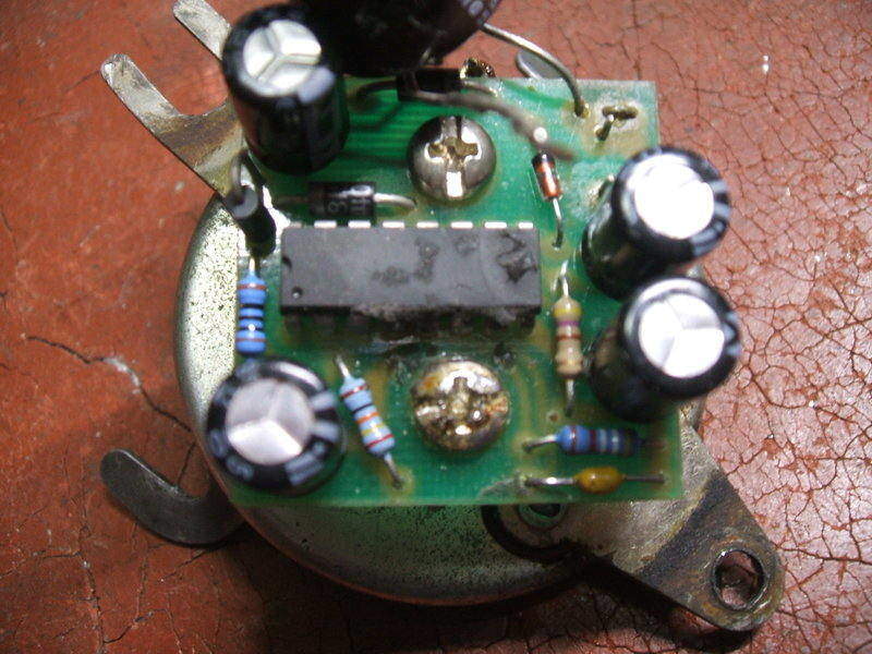
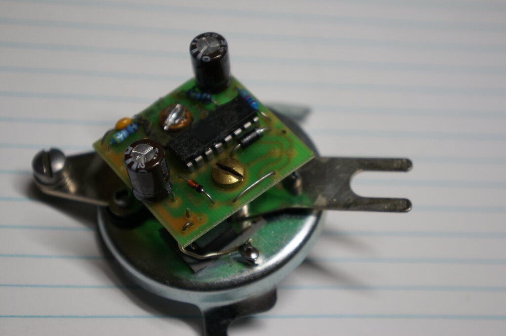
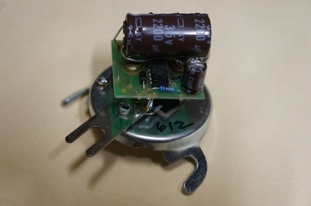
Component side of the PCB.
The Cut-out Diode.
Obviously, the diode was a dual Schottky
type. I've serviced enough switchmode power supplies to have recognised
it as such. Plus, logic tells that this would be the ideal type to use
here. The reason being that a Schottky diode has less of a voltage drop
across it than a silicon type. This means less heat dissipation for a given
current, and less heatsinking is required. In fact, the body of the regulator
housing is sufficient for this purpose. Typical types would include MBR30H100CT,
rated at 30A and 100V.
The Switching Device.
A bipolar power transistor could have
been used, but given the current it would have to switch, and the lack
of heatsinking, a MOSFET was the likely candidate. As the 'on' resistance
of a MOSFET is a fraction of an ohm, it means very little voltage drop,
even at high current. Hence, low power dissipation. Besides, MOSFETs are
easy to drive straight from regulator IC's, as this one was. A further
clue was the 470R gate pull down resistor between gate and source terminals.
A bipolar transistor would not need such a low value of base resistor because
the the base is current driven. With a MOSFET however, the gate presents
as an open circuit, and the drive source needs to be low impedance to switch
off the MOSFET very rapidly. A slow turn off will cause overheating due
to operation over the linear part of the curve.
Indeed, a quick test confirmed it was
a MOSFET. A good choice would a type such as IRF640 or STP60NE06-16. One
important specification of the MOSFET used is that the gate voltage required
to turn the device on is no more than about 5V.
The Integrated Circuit.
As to the IC, several options suggested
themselves. But first, before getting carried away with guessing, it was
necessary to trace out the circuit. As there are few external components,
this was straightforward. Having done this, several clues became apparent.
Two things indicated it was a switchmode regulator IC - this being gleaned
from the .0047uF and 49.9K resistors - obviously the time constant of an
RC oscillator. The one and only zener diode was 15V, and with a voltage
that high, was clearly part of the crowbar protection. It was obvious that
the voltage reference was internal to the IC; another feature of purpose
designed switchmode regulator IC's. And of course, with my previous testing
of the unit, the high frequency oscillation present was another confirmation.
Now, to get a block diagram of this IC
to analyse operation requires knowing the exact type number. 16 pins immediately
narrows it down to a few types. Then by looking at the function of the
pins we can match them up. For example, the timing resistor and capacitor
need to be on pins 6 and 7 respectively.
Also the output to drive the MOSFET needs
to be pin 14, and/or 11. We can also see the output voltage is monitored
at pin 2 via a voltage divider - obviously the input to the error amplifier.
Using the values of resistors connected to this terminal, and knowing the
regulation should commence at about 7V, the reference voltage of this IC
was calculated to be around 5V. This immediately eliminated several types
from the list of possibilities. Pin 9 would appear to be able to shut down
the IC should the 15V zener conduct.
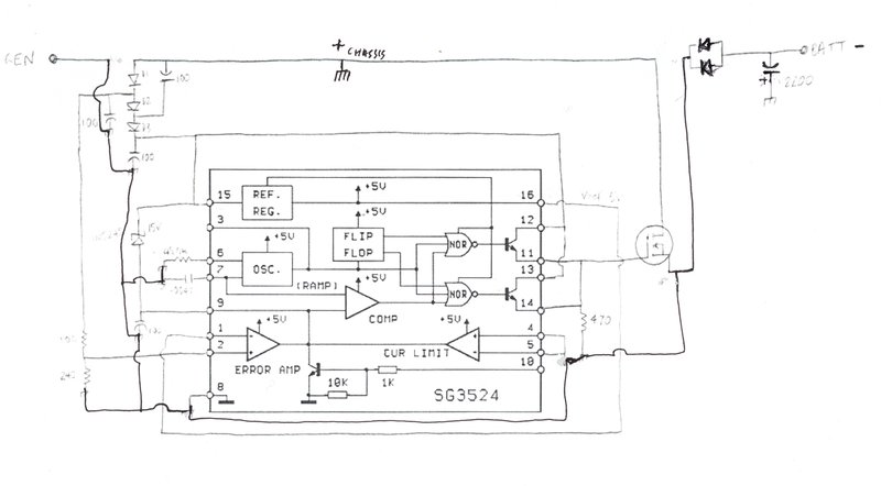
The 3524 family of regulator IC's fits
these pin connections.
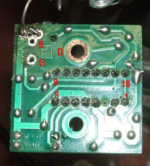
Track side of the PCB. IC pin numbers and MOSFET pins are labelled.
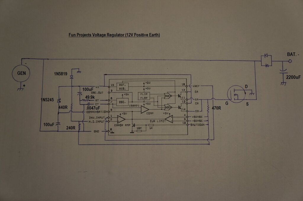
The Circuit.
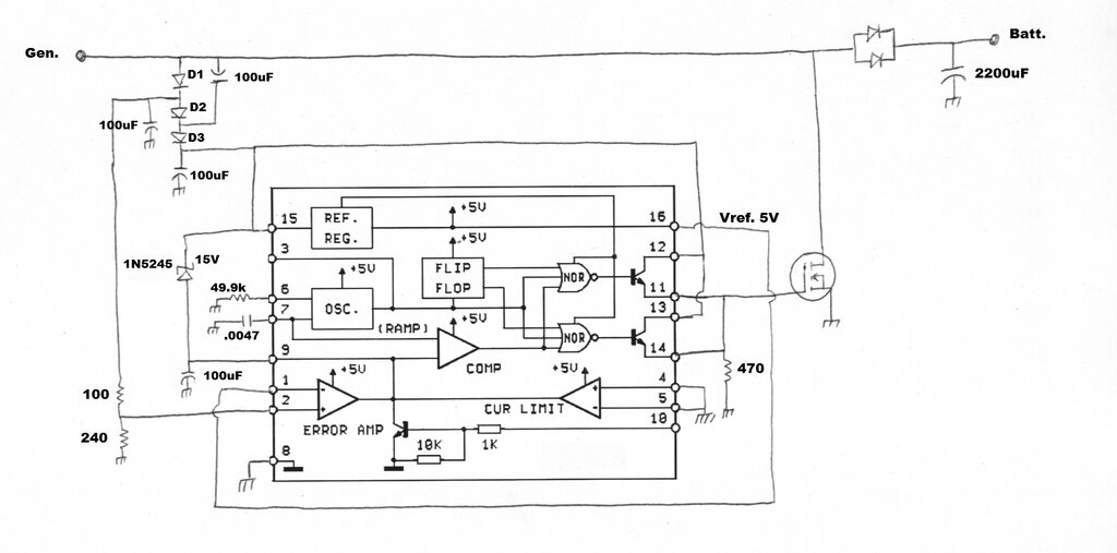
Investigation reveals the IC is likely to be from the 3524 family.
The MOSFET and Schottky diode have already
been discussed. The IC receives supply to pin 15 via the chain of diodes
D1 to D3. These are type 1N5819 Schottky diodes.
Apart from reverse polarity protection,
this chain of diodes, and their associated 100uF 50V capacitors,
also function as a voltage multiplier. Once the battery voltage reaches
about 7V and the MOSFET starts switching, there is effectively an AC component
present at the generator terminal. By multiplying this, we can get sufficient
voltage for the IC to perform properly. Apart from increased drive to the
MOSFET, the internal voltage reference is more accurate. There is about
13V present at pin 15 once regulation commences.
The charge retained in the 100uF connected
to pin 15 would keep the IC powered up during 'dead time'; i.e., when the
MOSFET is switched on.
The output of the IC drives the MOSFET
gate from two emitter follower output stages, at pins 11 and 14. In a push
pull type power supply, these two outputs are used anti phase, but in a
single ended regulator they can be paralleled. The supply also has to feed
the collectors of the driver transistors, via pins 12 and 13.
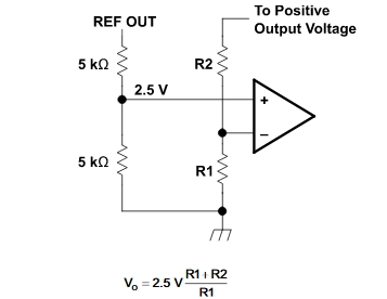
Battery Voltage Sensing.
The battery voltage is sensed via a voltage
divider feeding pin 2; the non inverting input of the error amplifier.
This is compared to the reference voltage (5V) internally generated in
the IC, and made available at pin 16. Note that the input to the voltage
divider is not the actual battery voltage, but the battery voltage plus
the drop across the Schottky cutout diode and D1. We can work out the voltage
at which regulation commences. With 5V across the 240R resistor, there
will be 7V at the junction of D1 and D2. Adding 600mV onto this gives 7.6V
at the generator terminal, and losing about 400mV across the cutout diode
(Schottky) means about 7.2V at the battery, which is what we want. It would
appear D1 and the associated 100uF decouple the voltage sensing input from
commutator noise, and again provide reverse polarity protection to this
part of the circuit.
Because the battery voltage is sensed
at the regulator, and not at the actual battery terminals, wiring resistance
will affect the battery charge voltage. In my instance, the battery terminal
voltage reaches 6.8V, although there is 7V at the regulator terminal. It
can be seen that because of the charge current (let's say 5A) combined
with the wiring resistance (let's say .04 ohms), some voltage will be dropped
across the wiring (200mV). When the regulator output terminal reaches 7V,
there is therefore 6.8V at the battery. And, since the regulator is designed
to terminate charge at 7V, it is clear that 6.8V is the highest voltage
the battery will charge to. However, at low engine speeds (and a lower
charge current), the voltage dropped in the wiring is less, and the battery
voltage does in fact increase up to 7V.
One obvious way around this limitation
is to use remote sensing; i.e. run a separate wire to the battery from
the error sensing input, or alternatively to locate the regulator right
at the battery. However, both options require wiring modifications. In
practice, the scheme works well enough, and battery charge voltage is not
that critical. Just make sure your wiring is in good condition so as to
minimise the voltage drop when charging.
The ramp generator to generate the variable
pulse width relies on the resistor and capacitor at pins 6 and 7 to set
the oscillation frequency. In this application their values are not critical,
and they appear to have been merely selected as being mid way of the specified
range of recommended values.
Crowbar protection for the generator (and
the IC) is performed by the 15V zener. If the battery should be disconnected,
the generator voltage will rise to an excessive figure. The zener conducts,
and pin 9 starts to go high. This then forces the MOSFET to switch on and
short the generator to earth. It may be wondered why pin 10 is not used
despite being the official shutdown pin. This is because taking pin 10
high actually turns off the switching device, as would be required in the
conventional kind of regulator circuit. Here, we want it to turn on the
MOSFET to shut everything down. Pin 9 is the inverse of pin 10.
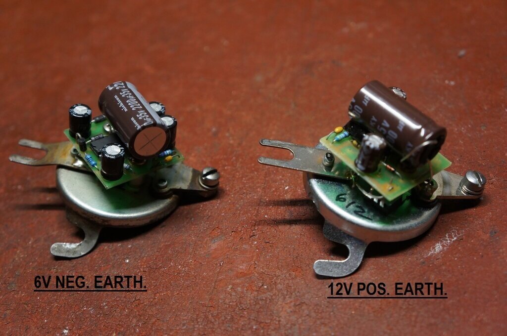
The 6V regulator could be simply modified
should the owner wish to change to a 12V system, having already purchased
the 6V model. The 100R resistor would need to be increased to 413R. The
100uF connected to the junction of D2 and D3 should be removed as we don't
want the voltage multiplier functioning at 12V.
Likely Faults.
The most vulnerable component is the MOSFET
and cutout diode. If the negative earth version of regulator was installed
in a car that had been converted to positive earth, the cutout diode would
immediately conduct. D1 and D3 will prevent the reverse polarity reaching
the IC or the 15V zener (which would fully conduct on reverse polarity).
However, there is an internal diode between drain and source inside the
MOSFET. This would conduct. Assuming no fuses between the battery and regulator,
a rather high current will flow until one of the diode junctions is blown
open. So, expect to replace the cutout diode and MOSFET if this has happened.
Another scenario is if the generator should
be 'flashed' after this regulator has been installed. If the MOSFET should
be conducting when the battery and generator terminals are bridged out,
the MOSFET will be blown apart internally.
When installed correctly, neither a short
circuit to earth at either the generator or battery terminal will harm
the regulator.
Positive Earth Regulator.
For the Model A owners, Fun Projects also
produced a positive earth version of the regulator. I have not had a 6V
type to reverse engineer, but I would expect it to be as per the circuit
below. In essence the circuit is flipped upside down in the electrical
sense.
Theoretical circuit of the 6V positive earth regulator. This has
not been confirmed in practice.
A postive earth 12V regulator has been
reverse engineered, and its details appear further down.
What is the IC?
Subsequent experimentation to reconstruct
the regulator on a breadboard revealed that the IC is not an SG3524. Trying
an SG3524 in the actual FP voltage regulator was not successful either.
The problem is largely to do with the error amplifier. The unmarked IC
has about 3V at pin 9 (the error amp output), whereas there is nothing
with the SG3524. Aside from that, it was found that the internal oscillator
operated with a level of 3V p-p at pin 7 with the unknown IC, and oscillation
started when pin 15 reached 3V. The SG3524 required pin 15 to be at 5.4V
for the oscillator to start, and the oscillation level was only 2V p-p.
There was no gate drive to the MOSFET unless pin 9 was taken slightly high
with a resistor, but there was no regulation. The crowbar circuit does
work with the SG3524.
Update Feb. 2019: A reader
has drawn my attention to the LM3524D, in that the common mode voltage
range of the error amplifier has been raised to 5.5V to eliminate the need
for a resistive divider for the 5V reference. Interestingly, the Fun Projects
circuit does not have the resistive divider that appears in the SG3524
application notes. The LM3524D therefore fits this description. I have
not actually tried an LM3524D, since I had difficulty obtaining one at
the time I did the reverse engineering. It seems the DN suffixed IC is
more readily available, and this also has the appropriate characteristics.
This also eliminates the NTE1720 since it has a 2.5V common mode voltage
range like the SG/LM3524.
What we're looking for is a version of
the 3524 which has a common mode voltage range of 5V, and will start operating
below about 7V.
It appears this modification is required to use the SG3524.
Update May 2019: Another
reader has confirmed that the SG3524 works as a replacement, by including
the resistive divider at the error amp input, and readjusting the divider
at pin 2. This was for the 12V version of the regulator. See above circuit.
Testing the LM3524D.
The LM3524D is now considered obsolete,
but in August 2023, I ordered some off eBay. It appears the DN suffix is
the
only type available and this is what was ordered. All the data points to
these being electrically identical to the D suffixed type.
Regulator works to some degree with LM3524DN installed.
The original IC was removed and an LM3524DN
installed in its place. I installed an IC socket on the PCB since the pads
and tracks were beginning to deteriorate from lots of IC swapping. Results
were interesting in that it did work, but only if the voltage to the generator
terminal was suddenly applied.
If the voltage was increased gradually,
the MOSFET is held permanently in its linear operating area. There is no
PWM action. The output voltage is then 6.2V, and of course the MOSFET gets
rather hot.
The oscillator starts at 3.2V, and remains
oscillating under this incorrect operating condition. The unknown IC starts
oscillating at 2.9V. The problem appears to be with the error amplifier
and/or comparator, because as the voltage is increased the voltage at pin
9 (the error amplifier output) increases up to about 5V and there is still
no PWM output at pins 11 & 14. Something is causing this latched up
condition because if the supply is momentarily interrupted, the regulator
starts and functions normally. Alternatively, pin 9 can be momentarily
taken low to 'reset' it.
Of course, in the car this is not satisfactory
since the generator voltage increases gradually. No doubt the LM3524DN
can be made to work with some alterations, and this will be investigated,
but it hasn't answered the question yet.
The UC3524AN. This was another
likely possibility, since it also has the right common mode voltage range
for the error amplifier. However, this IC includes an under voltage shut
off feature, which prevents the entire IC, except for the voltage reference,
functioning below 8V.
Nevertheless, some UC3524AN's were ordered,
just in case this 8V was more of an official rating than in practice. Results
were that this IC worked - but only if the battery terminal on the regulator
got to 7.9V. Once it started regulating, it continued to do so once the
voltage started to drop, because of the voltage multiplier circuit feeding
the Vcc pin of the IC.
Obviously, this is not the right IC, and
is not suitable since the battery voltage has to rise to an excessive level
for it to start working.
The SG3542BN. We're running
out of possibilities for 3524 variants with 5V common mode input voltage,
but the SG3524BN is another. Its under voltage shutdown is 4.5V. With that
looking promising, some were ordered.
Unfortunately, this turned out to be a
complete failure. Oscillation did not start until the supply was up around
15V, and the output voltage then regulated to around 9V. These results
are so strange that I wonder if the IC's are fake, which is possible considering
where they came from.
An Experimental Voltage Regulator.
Using the grounding switch method of control,
I have developed a voltage regulator which may interest those who are unable
to obtain the Fun Projects regulator. It uses easily available parts.
Homemade regulator uses comparator controlled grounding switch.
Fun Projects Regulator for the Model
A Ford (Positive Earth).
As has been mentioned, Fun Projects also
made a regulator for the Model A Ford. Originally, the Model A used the
same mechanical cutout as the Model T. Even though the Model A was the
first Ford to use positive earth, this was of no consequence, since the
mechanical cutout is not polarised.
When this is replaced with a modern diode
cutout or regulator, one designed for positive earth must be used.
As is the case with Model T's, a lot of
Model A owners have installed a 12V battery. Again, the third brush generator
used in the Model A can charge a 12V battery, since it operates as a constant
current source.
Thus, Fun Projects produced two regulators
for the Model A; one for 6V positive earth, and one for 12V positive earth.
The same housings are used as with the Model T versions.
Reverse Engineering the Model A Voltage
Regulator.
A new Model T owner contacted me regarding
a cutout - it was the last thing he needed to complete his car.
As it happened, the local parts supplier
just happened to have what he thought was a Model A cutout. I suggested
that this be purchased, and that I could convert it to negative earth.
The Model T owner mentioned he was using 12V, but being a diode cutout
this would not be important. All that needed to be done was to reverse
the diode.
In due course, the 'cutout' arrived. A
very nice surprise was that it actually turned out to be a Fun Projects
voltage regulator! So he definitely got his money's worth, and all to the
better. It was the 12V positive earth version of the regulator. My job
was to convert it to 12V negative earth for his Model T.
The cover was removed by grinding away
the two spot welds with a Dremel tool.
And here things became interesting, once
all was revealed inside. It turned out to be exactly as I had assumed previously.
The voltage multiplier used in the 6V version was absent, and the circuit
was as I had assumed it would be, as shown previously. It was 'flipped
upside down' in the electrical sense, but was otherwise the same as the
negative earth version.
Nevertheless, the circuit was traced out
to confirm this.
The PCB is identical for both 6V, 12V,
positive and negative earth. Not surprisingly, the IC, cutout diode and
MOSFET were again devoid of type numbers. But, as we have seen previously,
this need not present an obstacle.
PCB from the 12V positive earth regulator.
Comparing the negative and positive earth
regulators, we can see all the same parts there, but rearranged. Interestingly,
in this regulator, pin 10 of the IC has been earthed (note the zero ohm
link between pins 8 and 10). In my 6V negative earth regulator, pin 10
is not connected. This is the shutdown pin which is not used anyway. Internally,
the shutdown transistor base is already loaded with a 10k resistor. I assume
this zero ohm link was just added to make sure the shutdown would not be
triggered. Possibly a later improvement.
Note the PCB is rotated 180 degrees.
The 12V regulator PCB is a lot less cluttered,
since two diodes and two 100uF electrolytics are no longer required. In
the 6V version, these components are used as a voltage multiplier to increase
the supply voltage for the IC. The IC supply comes from a single 1N5819
diode fed from the generator, and is filtered by a 100uF. The shutdown
zener diode is still the same 1N5245. And, as before the RC time constant
for the oscillator is the same; .0047uF and 49.9k.
Of course, being 12V, there is some variation
in the feedback circuit to the error amplifier. The 240R remains the same,
but the other resistor is now 440R.
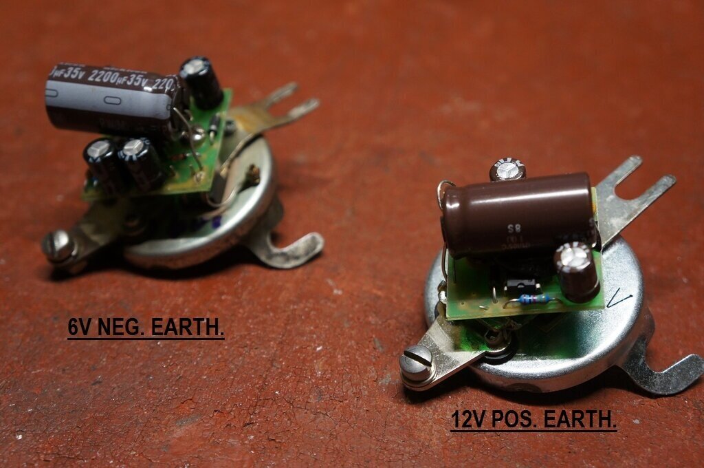
Component layout for 12V positive earth version. The voltage multiplying
diodes and capacitors are not used.
Looking at the chassis, the diode is reversed, as expected. However,
the diode position has been swapped with the MOSFET.
Converting to Negative Earth.
The design is actually quite ingenious
in that for the positive and negative earth version, the parts used are
all the same. Essentially, it is a matter of how they are physically arranged
and connected.
First thing to deal with is the chassis.
The diode and MOSFET were swapped.
To connect the diode, the connection arm
from the battery terminal, which had been bent over for the positive earth
version, had to be bent back. It connects to the diode cathode (the tab
of the TO220 case). The two outer anode leads were then connected to the
generator terminal. At this point we had a negative earth cutout.
Next, the MOSFET had to be installed with
an insulator, since the drain (the body) was now connected to the generator
terminal, and not the chassis. Additionally, the screw also required an
insulator.
Diode and MOSFET positions swapped.
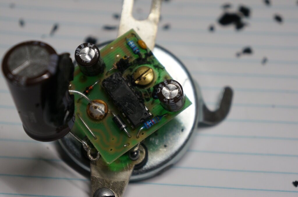
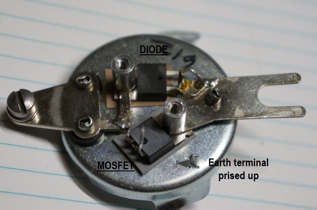
There is a "V" shaped stamping in the chassis.
In the negative earth version, this is the earth terminal. Thus, it was
prised up from the chassis.
Since the MOSFET is now in the other position,
it follows that the PCB is now mounted 180 degrees around from where it
was before. Everything lines up perfectly.
Earth terminal of PCB soldered to chassis via prised up "V" shaped
terminal.
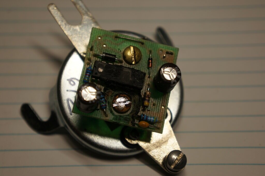
Resistor at left of IC is 440R. Under that to the right is 240R.
The 470R gate load resistor is to the right of the IC, and the oscillator
RC components in the bottom right corner. At the top left of the IC is
the 1N5819, and to the right is the 1N5245.
Regulator is now negative earth.
Regulation waveform at generator terminal.
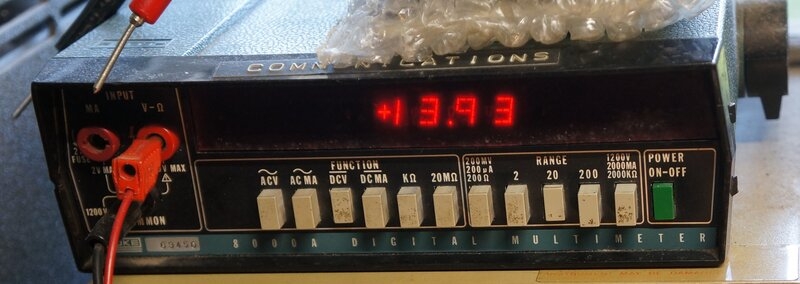
13.93V charge voltage into simulated load of a 60,000uF capacitor
and 12V 5W lamp.
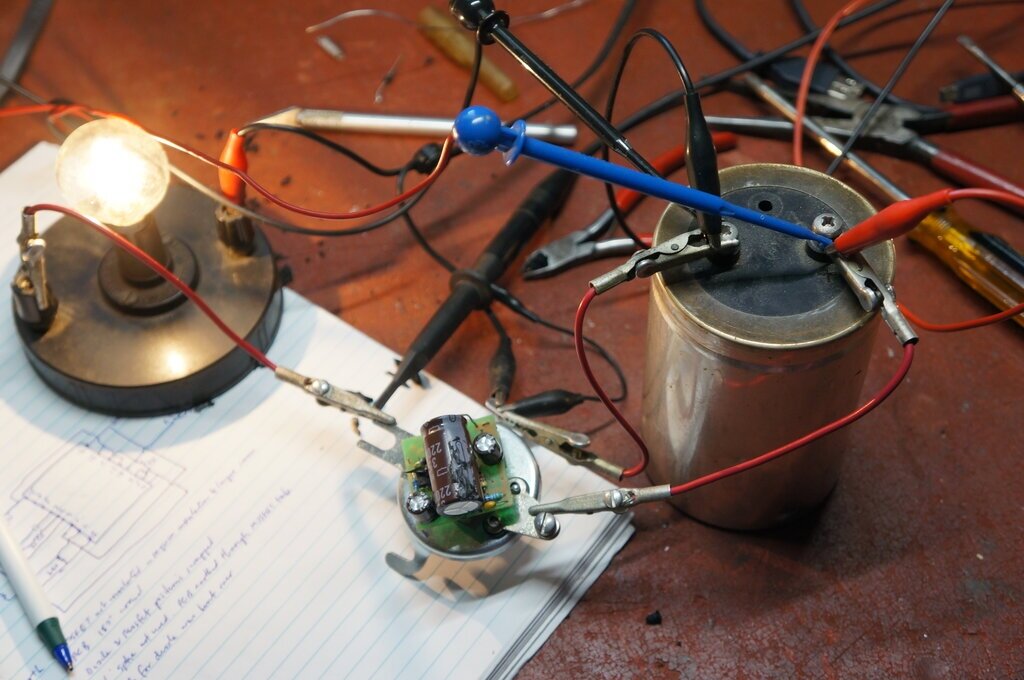
Test setup is a 16V power supply in series with a 12V 36W lamp to
simulate the generator.
2.5mm screws replace spot welds.
The final part of the job was to secure
the cover. Holes were drilled and tapped to take 2.5mm screws. This will
allow ease of future servicing if required.
New Replacement for the Fun Projects
Voltage Regulator.
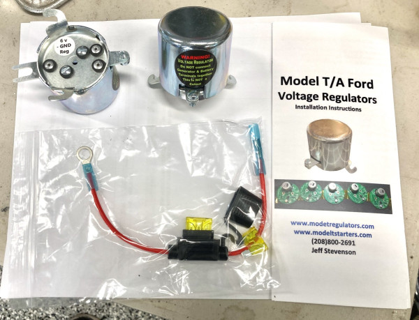
As is well known, the Fun Projects voltage
regulator was discontinued when Fun Projects was sold to Birdhaven. There
is still a demand from Model T (and Model A) owners for these regulators,
since they were a very popular and highly regarded accessory.
After a couple of years of design and
testing with a group of fellow Model T owners, I am pleased to announce
that a new regulator has gone into production and is now available. Like
the FP design, the new regulator is built into a cut out can, and is a
simple drop in replacement for the original cut out.
At the present time (March 2024), regulators
are available for 6 and 12V negative earth (for Model T). For the Model
A Ford, a 6V positive earth design is undergoing testing and will be available
soon.
You can order them here:
For the story of the development of the new
regulator, see
this article.
Home