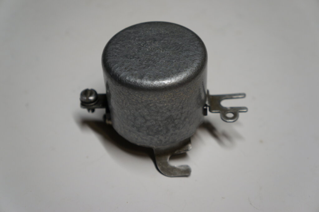
Final version built into cutout housing.
Final version built into cutout housing.
Prior to acquiring a Fun Projects voltage
regulator for my Model T, I had often thought about building my own regulator.
Its principles were going to use the grounding switch method, with a comparator
to 'ground the generator' when the battery reached full charge.
The principles of this, and the regulation
methods for the third brush generator, have
been described in this article.
Out of curiosity, I breadboarded a design
on the bench which seemed to work well for what it was. At the time, I
never proceeded any further by testing it in the car.
In recent times (end of 2021), there has been a lot of interest on the MTFCA forum about voltage regulators, since the Fun Projects regulator is in short supply. It has certainly been a popular accessory over the years, and from all reports, as well my own experience, it works very well. With some encouragement from forum members Mike Kossor (the designer of the ECCT, E- timers, and I-Timers), and Luke, a fellow electronics and Model T enthusiast, I decided to finish my project.
Let's Start at the Beginning:
First bench tested prototype. While it worked, it had a few problems.
Prior to examining the FP VR, I had assumed
it used a comparator instead of a PWM controller. In this regard it would
be like a regulator in a modern car, in that it switches off the generator
when the battery reaches full charge, and then switches it back on as the
voltage drops. This switching frequency and duty cycle would be dependent
on the load; the off time being quite long if the battery was charged and
lightly loaded.
Experiments were made to see if my initial
assumption was plausible, and the circuit above was constructed and tested
on the bench. Like the FP VR, this circuit could also be built into the
body of a mechanical cutout, and be used as a drop in replacement.
It uses the "grounding switch" method for
regulation. A MOSFET was also chosen as the switching device because of
the low "on" resistance (.013R) meaning that little heatsinking is required,
and the high resistance gate is easy to drive. A Schottky diode was chosen
for the cut out also due to the low voltage drop, and thus minimal heat
generated.
The heart of the circuit is an LM393 comparator.
The non-inverting input is held at a constant 2V by a red LED which is
powered from a 470R resistor from the battery. Also across the battery
is an adjustable voltage divider, comprising of a 10K pot and 560R resistor.
When the voltage at the pot wiper (inverting input) exceeds 2V, the output
at pin 1 goes high. The output drives the MOSFET gate high which then shorts
out the generator. It can be seen that if the voltage divider is set so
that pin 1 goes high when the battery reaches 7V, the battery will never
be over charged.
Pin 1 is connected to the battery supply
via a 2.2k resistor because the LM393 has an open collector output. Because
of this, an emitter follower using a BC548 is used to drive the MOSFET
gate. This is because the MOSFET must have a gate pull-down resistor to
ensure it switches off completely when the LM393 output is low. If it wasn't
for the emitter follower, gate voltage would be reduced because of the
voltage division that would occur, and the MOSFET might not switch fully
on. If this happens, it will overheat because of operating in its linear
mode.
The switching would be unstable if not for one other component, the 15k resistor. This introduces hysteresis so that the turn off voltage is slightly less than the turn on voltage. When the output of the comparator goes high, the positive input of the comparator is raised slightly by means of the extra current flowing through the 560R. This means the turn off voltage must be made somewhat less than 7V (e.g. 6.5V). This provides a definite and clean switching point. Without it, the circuit oscillates at a high frequency around the comparator triggering point.
At this point the circuit is quite practical,
but as the voltage divider, LED, and LM393 draw current, there would always
be a drain on the battery. Unlike the FP design, the regulator circuitry
here operates from the car battery; not from the generator directly. If
the car was used every few days this would not be a problem, but we cannot
count on this. This problem is eliminated with a second BC548. It will
be seen that the earth return of the regulating circuitry is via this transistor.
When the generator is rotating, the BC548
is biassed on by the 10k base resistor connected to the generator output,
and thus the earth circuit is completed. When the generator is stopped,
the BC548 appears as an open circuit, and there is no drain from the battery.
The 47k base resistor ensures the transistor
is really off when it should be, although it is true the return path through
the 10k, and the low resistance of the generator would do the same thing.
The 100uF filters out generator noise that might interfere with the BC548
switching.
The circuit was bench tested and provided excellent results. With a 12V 5W lamp instead of the 6V battery, the circuit switched at about 100Hz. In this situation, the 2200uF simulated the battery time constant. No doubt with a proper battery the switching would be slower. The generator was simulated by a 10A variable power supply, fed into the regulator via a 12V 36W bulb for current limiting, which was in series with the secondary winding of a 14V transformer, to simulate generator inductance. Over voltage protection is inherent in this design, so that nothing is damaged if the battery is disconnected with the generator running. Output remained at 6.8V with the load disconnected, and the input increased to 16V.
Thoughts were to simplify the circuit further,
by removing the BC548 emitter follower, connecting the MOSFET gate directly
to pin 1 of the LM393. The open collector output of the LM393 would take
the MOSFET gate to earth when it needs to be switched off, and in so doing,
the 1k gate resistor can be removed. The 2.2k load resistor is probably
low enough to overcome the gate capacitance, and allow a rapid switch on
for the MOSFET. If possible, the 2.2k should be reduced in value to allow
a faster switch on. The lowest suitable value would depend on the current
rating of the LM393, which appears to be 20mA. On this basis, the resistor
could be as low as 350R with a 7V supply. 470R would be a good choice,
allowing for a margin of safety.
Another point to consider if the emitter
follower is not used, is the loading of the 15k hysteresis resistor. This
is going to prevent pin1 of the LM393 rising to the full supply because
of the voltage divider action between the 560R + 15k and the pin 1 load
resistor. If we assume a supply voltage of 6V and a 470R load resistor,
the gate voltage will be 5.8V, which is acceptable.
Mike had simulated my original bench circuit,
and while it worked, his simulation revealed one obvious error. I'd used
a huge capacitor (60,000uF) to simulate the battery. When a real battery
was connected, the MOSFET was always biassed on, preventing the generator
coming up to voltage. Effectively, the circuit was locked out. Of course,
with a capacitor, its voltage falls to zero when not in use - hence the
trap!
I had also wanted to eliminate the emitter
follower driver to the MOSFET. The reason for its inclusion was only so
that the regulator could be disconnected from the battery, and draw no
current when the generator was not rotating. My battery switch was in the
earthy side of the circuit, but by relocating it to the positive side,
the MOSFET could be driven directly. This was my first redesign of the
circuit.
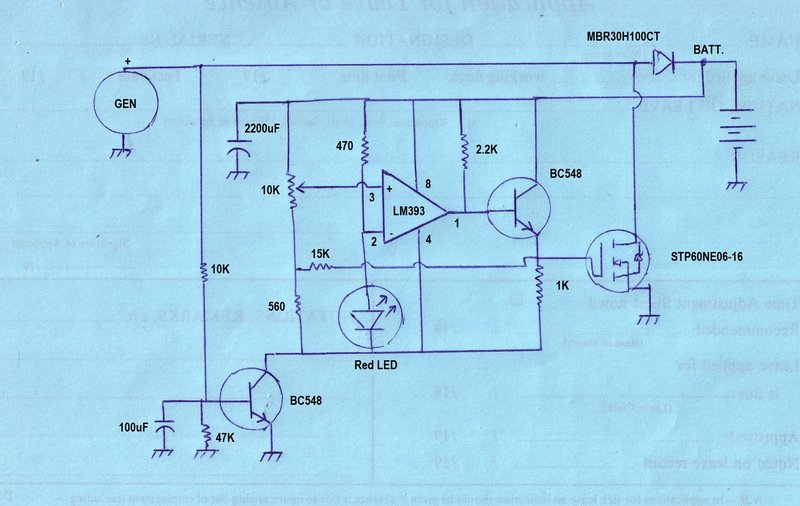
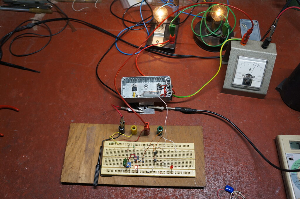
Second Prototype (December 2021).
My original circuit was modified as shown.
For development, I simulated the generator with a 12V 10A power supply
in series with two 12V 36W light bulbs in parallel.
The main fault in the original circuit
was that with the regulator circuit off (when the the generator was not
running), the MOSFET is still biassed on. There is a resistive path from
the battery, via the 10k trimpot, the 560R and 1k gate resistor into the
MOSFET gate. This prevented the generator voltage coming up in the first
place, to get the circuit started.
To correct this, it was necessary to switch
the positive supply to the regulator circuit; not the negative as previously.
Two transistors perform this function; the BC548 switches on when the generator
starts rotating. This in turn switches on the BC558, which connects the
battery to the regulator control circuit. Even when the MOSFET switches
on, there is enough voltage drop across the cutout diode to keep the BC548
switched on.
Having done this, it was possible to remove
the emitter follower which drove the MOSFET gate. Now, the LM393 drives
the gate directly and required only a simple pull up resistor. This was
reduced to 470R in view of directly driving the MOSFET and its gate input
capacitance.
Shown is an optional charge indicator
with a LED in the LM393 output circuit. The LED comes on when the battery
voltage has risen to full charge, and the MOSFET switches on.
The preset voltage control was previously
too critical in its adjustment, since the 10k trimpot was across the entire
battery voltage. To improve this, it's been padded out with resistors.
Finally, the hysteresis circuit has been
simplified with just a 220k resistor between the LM393 output and the positive
input.
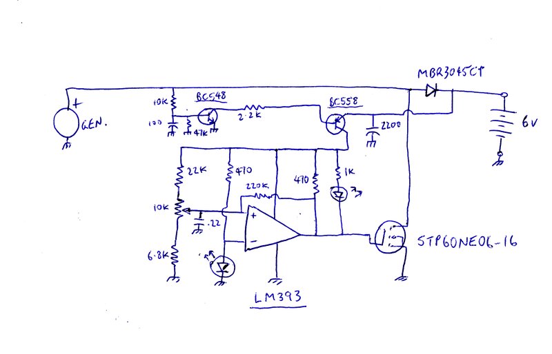
Third Circuit.
The above circuit had a problem in that
the BC548-BC558 battery disconnect switch was not perfect. The supply rail
for the LM393 fluctuated as the circuit switched, which affected the triggering
point.
Third circuit worked well except for a high standby current. "Charging"
designation on the LED should read "Charged".
So why not get rid of the battery switch
altogether? Two things occurred to me; 1). The current through the 22k,
10k, and 4.7k was only 150uA. 2). A high brightness LED will work at less
than 1mA, so why not use that as a voltage reference?
And so the circuit was modified. The high
brightness LED made a good 1.75V voltage reference, drawing about 450uA.
With such a low current consumption, the
circuit could be left across the battery all the time. The circuit would
be drawing less than the self discharge current of the battery itself.
Regulation was good and the circuit looked promising. Alas, when the generator was disconnected, the current did not decrease as expected. It actually went up! This seemed illogical, until I thought about the operation of the circuit. With the battery not fully charged and the generator stopped, the MOSFET was switched off, as it should be. However, in order for this to happen, pin 1 of the LM393 has to go low. This in turn means there is a current of about 12mA flowing through the 470R resistor (slightly more with the "Charged" LED in circuit).
I thought about ways around this, using
both sections of the comparator, one as an inverter - but always came back
to the same problem: Battery at rest means the MOSFET has to be switched
off, in readiness for when the generator next comes into operation - which
in turn means the gate has to be earthed.
Increasing the pull up resistor at pin
1 to reduce the current draw would fix this, but it would be undesirable
due to the MOSFET gate capacitance. There is a risk the MOSFET would operate
in the linear mode at the switching on point. With the amount of current
being switched this could cause undesirable overheating.
Fourth Circuit.
One way around this problem to provide
a low impedance drive to the MOSFET, and to have a high value pull up resistor,
is to use an emitter follower.
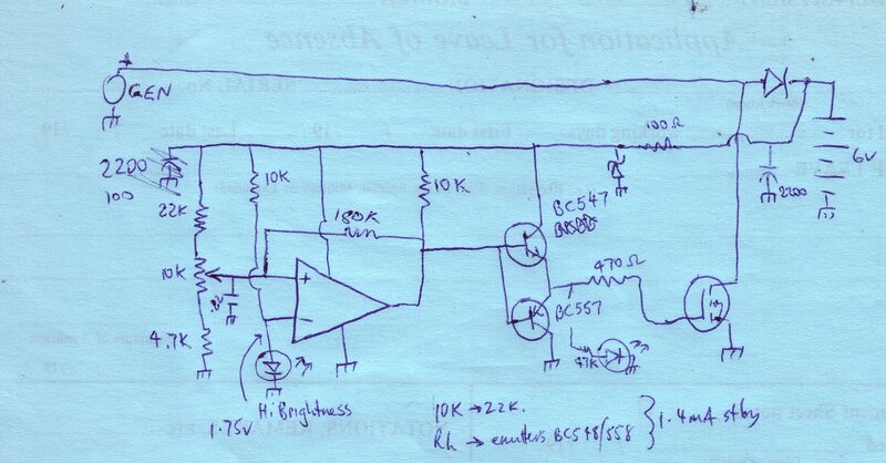
Circuit has a 1.4mA standby current.
A complementary-symmetry emitter follower
circuit drives the MOSFET gate. With a 10k pull up resistor, the standby
current was reduced to 1.4mA which is very acceptable. Some high frequency
oscillation was visible at the switching point, and this was largely removed
by the 470R gate resistor - standard practice for this kind of circuit.
In simple terms, the 470R in conjunction with the gate capacitance works
as a low pass filter. The "Charged" LED was changed to a high brightness
type, which in turn allowed its series resistor to be increased substantially,
to 47k. This was important, because the lower the output current of the
emitter followers, the lower their base current can be, which in turn allows
a higher pull up resistor - now 10k.
To give an idea of how the hysteresis
resistor affects operation, with 180k, the switching occurred at 6.77V
and 7.19V. Increased to 220k, the switching points were 6.86V and 7.14V.
It can be seen that the higher the resistor, the narrower the voltage range,
and thus the faster the switching frequency. Lowering the resistor lowers
the switching frequency, but also means the battery voltage drops further
before charging recommences.
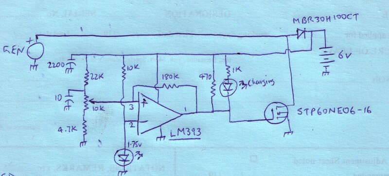
Final Circuit.
A few minor improvements resulted in the
final circuit which went into the car for real world testing.
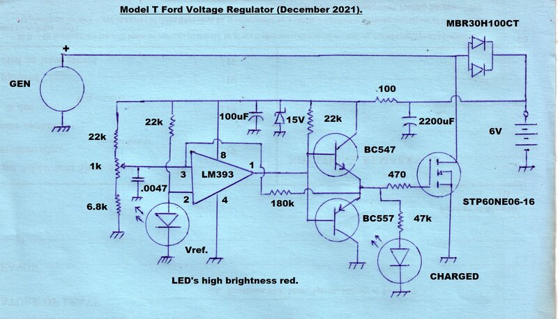
Final circuit has further reduced standby current and supply filtering.
In the previous circuit, it can be seen
that the base voltage of the BC547/BC557 pair won't get to the full supply
voltage, because of the voltage divider action of the 10k being loaded
down by the 180k hysteresis resistor. The answer to this is to simply drive
the 180k from the output of the emitter follower. Furthermore, this allowed
the pull up resistor to be increased to 22k. Now the standby current was
a very acceptable 1.2mA.
The high brightness LED seems to work
well as a voltage reference. With a range of battery voltage from 6.82
to 7.2V, the LED Vref is 1.747 to 1.741 which is a change of only 6mV.
In view of restricted space in the final
unit, the capacitor at pin 3 was reduced to .0047uF without any ill effect.
The preset pot was changed to 1k to make
adjustment less sensitive. Having said that, it's possible that given the
spread of LED characteristics, one of the resistors either side of the
pot might need to be changed for other individual constructions of this
circuit.
A final modification was the inclusion
of a 15V zener diode to protect against spikes from the ignition system,
or external battery chargers that might be connected. In addition, a 100R
provides current limiting for the zener, and noise filtering in conjunction
with the 100uF.
By default, the zener also provides reverse
polarity protection for the IC and transistors, should the battery be connected
in reverse.
The regulator circuit provides inherent protection for the generator, should the battery become disconnected with the engine running. The regulator immediately senses the terminal voltage as being above 7.2V, and shorts out the generator. Due to the time constant formed by the 100R and 100uF, the circuit begins to oscillate at about 29Hz. This is because the supply to the regulator is lost when the MOSFET conducts. The duty cycle of the MOSFET conduction is so high that no harmful voltage is developed.
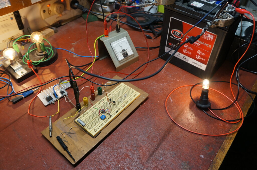
Construction of the Prototype.
At this stage of the design, I wasn't
ready to make a PCB, and nor did I have an empty cutout housing for the
regulator. Instead, the circuit was built on a piece of Veroboard mounted
inside a diecast alloy box. This in turn was riveted to an aluminium bracket
which was screwed to the generator.
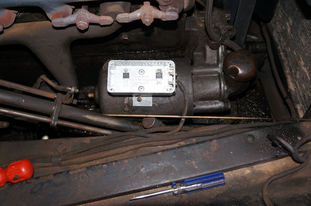
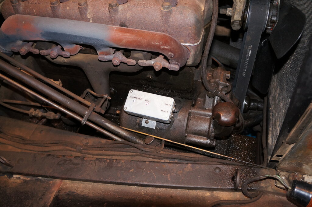
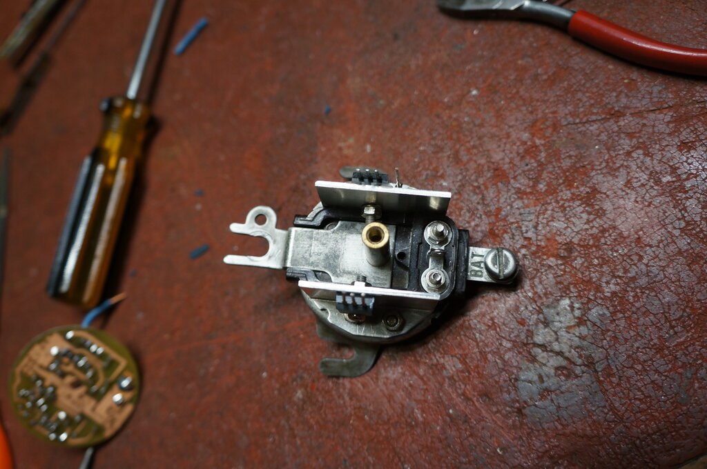
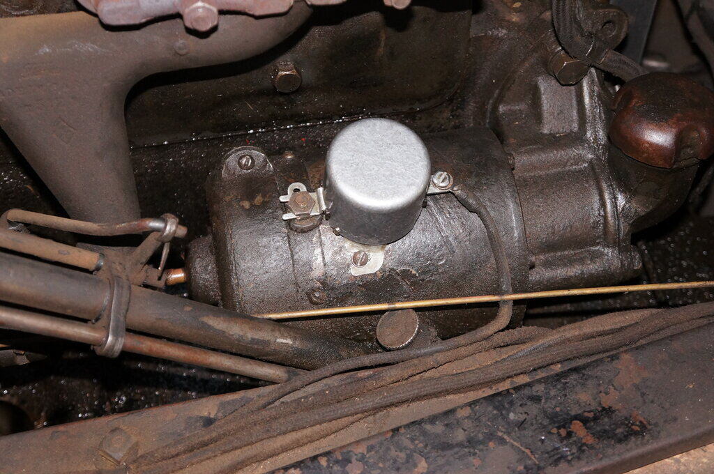
How the regulator mounts to the generator in place of the original
cutout. MOSFET and cutout diode have been screwed to the box for heatsinking.
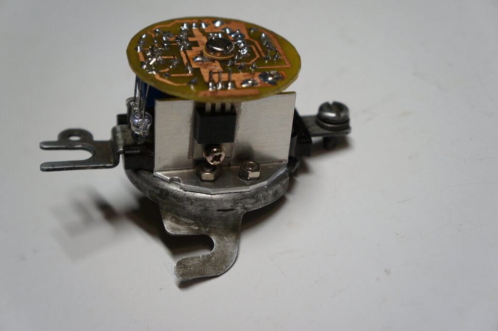
MOSFET and cutout diode mounted in diecast box. Circuit in its final
form before assembling on Veroboard.
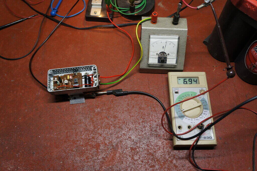
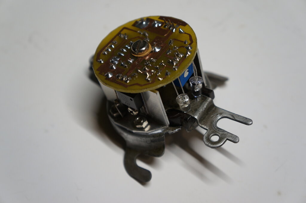
Final bench test before installation in the Model T.
The Big Test!
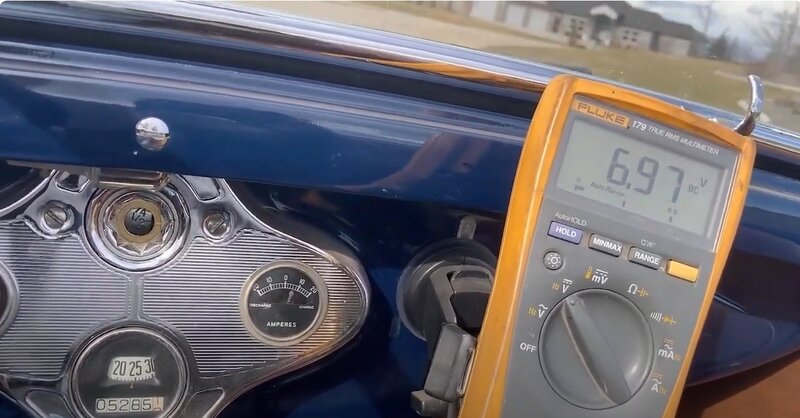
The regulator was mounted in the car,
and connected up. The Vref LED lit up as it should. The engine was started,
and it was a total anti-climax; the circuit started regulating within a
few seconds as the battery voltage came up. Switching was very clean and
not affected by the ignition system. Operating the headlights increased
the switching frequency as expected. Similarly, with no load except for
the ignition, the frequency was much slower. The trimpot needed a small
tweak; the voltage now being 6.6 to 7V.
I found that a Fluke 8000A digital meter
was affected by the ignition, so reverted to an AVO 8. This was no surprise
- some DMM's work on Model T's; others don't.
The rest of the story is best told by
watching the demonstration video.
Battery Charging Fallacies.
Once a battery has reached full charge,
it is undesirable to keep pumping current into it. Many non-electrically
minded Model T owners are uncomfortable unless their ammeter is always
showing a charge.
Many also operate with an unnecessarily
high charging rate; 10A or more - worried that they might get caught with
a flat battery if it's any less. Indeed, the Ford manual does suggest 10-12A
for the charge current, so it's easy to see where this apprehension might
come from. When Model T's were used as every day cars, there might be some
justification for this, with frequent starter motor and headlight use.
So what happens after continuing to drive
once the battery has reached full charge? The battery temperature increases,
the terminal voltage rises, and electrolyte begins to be lost as hydrogen
gas is produced. And, the generator continues to run at its full charge
current, unnecessarily wearing the commutator, brushes, and bearings. In
summary, the battery and generator life is reduced. At particular risk
are modern sealed batteries - these can only absorb so much hydrogen gas
before damage occurs. It is well to note that the Ford Instruction Book
says to add water to the battery every two weeks!
Of course, a voltage regulator is an improvement,
because charging rate is reduced as the battery comes up to charge, stopping
altogether once full. Using a voltage regulator also allows a 10A charge
current to be used without harm, if this is desired. It is quite safe to
charge a battery at this, or higher currents, provided the
charge is terminated when the battery is full.
In actual fact, the charge current does
not have to be so high. Let's put this into perspective: The battery has
a capacity of around 100Ah for a typical wet lead acid 6 volt 13 plate
battery, or in the case of a Red Top Optima AGM battery, 50Ah. Considering
that the Ford ignition system would draw probably no more than 1A (while
the average current per coil is around 1.3A, the coils are not continuously
operating because of the dead space between the timer contacts), it can
be seen that the ignition can be run for a considerable amount of time
on one charge . Those with a working magneto don't even need to worry about
this scenario!
If the original, non regulated cutout-only,
charging system is to be retained, the charge current can be reduced to
the point where it won't be too harmful, once the battery is fully charged.
Around 5A is a practical compromise. In driving my Model T for 19 years
with a 5A charge rate, I have never had a flat battery, despite
occasionally using a car fridge (8A), sometimes driving for two hours at
night with incandescent headlights (10A), and using a valve radio (5A)
for the entire trip. For some of that time, the charge current is much
less than the load current, but that's the whole point of having a battery
- it contains a lot of reserve power to be used in such situations. For
example, if the charge rate is 5A, and the headlights draw 10A, then in
fact only 5A is being taken from the battery. Most Model T owners don't
even drive their cars at night anyway. While the starter motor might draw
150A, remember this is only for a few seconds, so in actual fact the overall
power consumption is very low. A rough calculation reveals that for a five
second use of the starter, a little over 200mAh is consumed.
A charge rate of 5A also has the advantage
that if the generator becomes unloaded due to a wiring fault, it is very
much less likely to cause damage to the windings - I know this from driving
quite some distance with a faulty mechanical cutout several times.
With the comparator type regulator, the
battery charge is terminated once the battery voltage reaches 7V (or whatever
the full charge voltage is set to). That's it; no need to put more current
into it. Only when the battery voltage falls to a certain point, either
by self discharge, or by a load connected to it, will charging recommence.
By that notion, it can be seen that switching frequency depends on the
current being drawn. With no load on the battery, the charging might occur
for 10 seconds, and then switch off for 40 seconds. With a load being drawn
which is higher than the charge current, the charging will be continuous,
and not switch off unless the battery comes up to full charge, by reducing
the load.
The whole point of this digression is
to illustrate that once a voltage regulator is fitted, the ammeter will
at times show zero charge current. This is nothing to worry about, and
merely indicates that the battery is fully charged and the regulator is
working.
Constructional Points.
For anyone wishing to duplicate the regulator
circuit, there is some choice regarding components.
Voltage Drop.
It may be seen that the switching voltages
are slightly different when the engine is running at idle, compared to
at high revs. The reason for this is the wiring resistance between the
regulator and battery. At low revs, charging current is low. Voltage drop
across the wiring to the battery will therefore be low. When charge current
increases with engine revs, the wiring resistance has more effect. Let's
assume a wiring resistance of .04 ohms. If the charge current is 5A, then
200mV will be dropped across the wiring. Now, because the voltage is sensed
at the regulator and not actually at the battery, we can see how this affects
the switching voltage. If we've set the regulator at idle speed for 7.2V,
at high revs the regulator will see 7.2V when the battery is actually at
7V. Luckily for a lead acid battery, the charge voltage is not that
critical. My recommendation is to set the charging voltage at high revs,
since this is when most of the charging time occurs. It goes without saying
that the wiring should be in good order with clean connections, etc. In
my instance, I have set the regulator for 7V at the battery, at high revs.
Finally, it should be pointed out that
the Fun Projects regulator suffers from the same limitation. This is difficult
to avoid unless remote sensing is used.
Note that the regulator described is a voltage regulator only. The current regulation is still dependent on the 3rd brush setting. This should have already been set to an appropriate current with the previous cutout, before connecting the regulator. Nevertheless, there is no reason the current cannot be adjusted with the regulator in circuit. It will be necessary to wait for the MOSFET "off" times (i.e. 'Charged' LED off) before adjusting the 3rd brush. To extend the off times while making this adjustment, turn on the headlights and other loads.
For 8V.
The Model T generator can charge 8 or 12V
batteries, since it functions as a constant current source. It is important
to derate the charge current under these conditions, in view of the 100W
maximum power rating.
So, for 15V output (cutout diode drop
+ 14.4V charge), the generator should not be set higher than 6.6A.
However, when Jeff Stevenson later tested the crowbar circuit in the production model (see further down), it was found that in fact the 2200uF should still be included. This is because with no battery the circuit would oscillate too rapidly causing the MOSFET to get hot, because it begins to operate in its linear mode. With the 2200uF in circuit, the voltage is held for a longer period which allows a definite switching point.
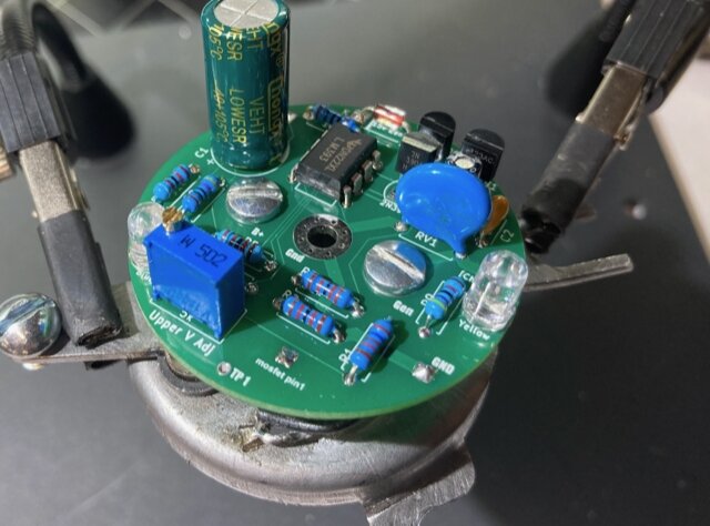
Heatsink brackets with diode and MOSFET attached. Central pillar
supports PCB.
Because of the large bakelite insulator, it was not possible to mount the diode and MOSFET as per the Fun Projects regulator. Instead, two aluminium heatsink brackets were made up to support these components vertically. It was hoped there would be sufficient thermal conduction to the base of the cutout housing. Thermal paste was applied between the surfaces to help this.
With the small space available, a PCB was essential. Veroboard, as used in the prototype, will not allow sufficient component density. And, so a board was designed using Protel, then etched, and drilled. The details of this process are described here.
Board is supported by the diode and MOSFET, and the central pillar.
The board was quite reasonable, given the
home made method of applying the 'resist'. There were no shorted or open
tracks. The main thing is a 'bluriness' with some tracks; I suspect caused
by the paper moving before it had heated up sufficiently under the iron.
Importantly, the electrons would never
know the difference! I should have allowed for one more size up for the
resistor lengths, but despite that, they could be made to fit. I was very
pleased that the board lined up centrally with the diode and MOSFET pins.
Vref and Charged LED's reflect off generator terminal strip.
A central brass pillar provided additional
support, as well as providing connection to the generator input terminal.
I tapped it for a 5mm screw on the base side, and for a 4mm screw on the
PCB end. Initial design was the 4mm screw would provide connection to the
relevant PCB track, but as this was slightly off centre, and was going
to short an adjacent connection, a fibre washer was put under the screw.
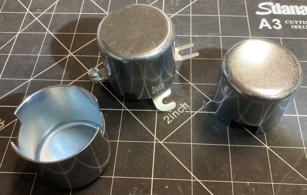
To keep the lid secured, I drilled and
tapped a pair of holes in the base to take 2.5mm screws. The lid needs
to be removable to set the voltage in the car.
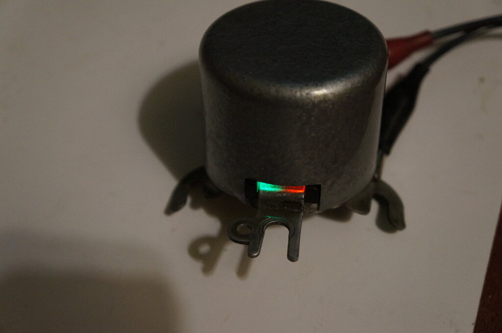
LED's visible through gap. Red shows Vref, and green shows the battery
is charged.
Some thought had to be given to making the LED's visible. I had decided to retain the LED's because of the convenience and reassurance offered in the prototype. Drilling holes in the cover was something I'd prefer not to do, but as it happened, there was a sufficient gap between the generator terminal strip and cover, for their light to shine out of. The LED's point down at the terminal strip and the reflected light is visible through the gap. This worked perfectly, and does not detract from the authentic appearance. Since there are two LED's which are not directly visible, the obvious way to differentiate between them was to make the 'Charged' LED green. (Changing the 'Vref' LED to green would have altered the reference voltage, requiring a redesign).
Initial bench testing showed all was well, and the unit was then mounted in the car:
Looks just like an original mechanical cutout, but prevents battery
overcharge.
Testing showed identical performance as compared to the prototype.
Final Thoughts.
The project is now complete and working
with the results I had hoped for. However, it should be pointed out that
the design of the cutout housing I used was not ideal from a heatsinking
perspective. The amount of thermal transfer is limited. Also, the mild
steel base is a less efficient heat conductor compared to aluminium. In
short, the alloy diecast box is technically a better construction. With
the cutout housing version, I would be reluctant to increase the charge
current beyond the existing 5A. Unless a diode with a lower voltage drop
can be found, I don't recommend this method of construction for higher
charge currents. At 5A, there is 450mV dropped across the diode, which
results in 2.25W dissipation. It runs warm, but not uncomfortably so. It
must be remembered that in the car, the body of the generator will also
actually add heat to the whole thing. A further comment needs to be made
with regards to the mounting of the cutout housings, whether repro or original.
The shape of their feet does not provide full contact under the screw heads.
In fact the more I look at it, the aluminium mounting brackets I made up
for my prototypes are far superior, and provide a much better mechanical
(and electrical) connection to the generator case. Furthermore, my brackets
allow the regulators to be stood off the generator with a flow of air underneath
- as well as keeping the regulator further from the hot generator body.
I'd only use a cutout housing again if I was building another unit for
someone who was concerned about original appearance.
As well as myself, over the past year or
so, testing was also done by MTFCA forum administrator Jeff Stevenson,
and the late Tony Bowker. Both had done their own modifications to the
design, but the principles of operation remained the same.
Although the TL494
switchmode regulator does the job, and is a perfectly viable option,
the preference was to produce the LM393 comparator design. This is because
the operation is very clear cut, and the driver knows by watching the cycling
of the ammeter, the state of battery charge, and that the regulator is
actually working! Over the years of using the Fun Projects regulator, at
times I would be wondering if everything was OK when the ammeter always
seemed to be at zero. Was the battery just fully charged, or had something
gone wrong with the generator? I'd have to turn on the lights or radio
for a while to create a discharge just to check it.
Jeff was already experienced in generator
and starter motor restoration, so it was natural to add regulators and
cutouts to his portfolio. With demand for regulators being 'on topic' again,
he took the plunge, and got the project to where the regulators are now
in production.
He has done an amazing amount of work
in creating the new enclosures and the tooling for them, as well as designing
the PCB and getting them produced. The electrical design is essentially
the same as the one I built for my own car, but Jeff has made a few minor
alterations, such as a voltage reference IC instead of a LED, some capacitor
alterations, and MOV spike protection for the MOSFET. The enclosures are
based on the Fun Projects design, since this had the ideal layout for a
PCB, and suitable heatsinking surface area.
All new regulator replaces the obsolete Fun Projects product.
12V Regulators for the Model T. To answer the demand from Model T owners who have converted their car to 12V, regulators for this voltage were soon developed, and are now available.
Early regulator production.
Model A Ford - Positive
Earth Regulators. As
soon as the new Model T regulator went into production, requests started
coming in from the Model A world, where the cars are also 6 volt, but positive
earth. Clearly, the project had to support this significant market.
Unlike the original Fun Projects regulator,
it wasn't just a matter of flipping the negative earth design upside down.
This is essentially because the new regulator is powered from the battery,
whereas the FP design powers it from the generator. This in turn affects
how the MOSFET is switched. The solution was to use the remaining inverter
in the LM393 and a P-channel MOSFET. Jeff did all the design work here,
since he's fortunate enough to also own a Model A.
Order regulators here https://modeltstarters.com/shop/voltage-regulators-cutouts/
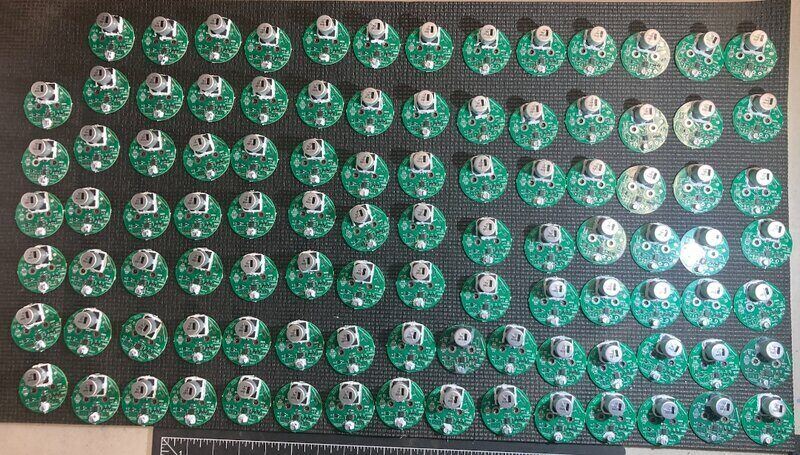
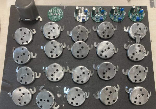
Regulators are now mass produced using surface mount components.
Anyone interested in how the project got this far should see these two links:
https://www.mtfca.com/phpBB3/viewtopic.php?f=19&t=38035
https://www.mtfca.com/phpBB3/viewtopic.php?f=19&t=38155