Opening screen of Easytrax.
My first PCB designs used Bishop tape stuck
to velum. UV light was then passed through this onto orange reversing film
to create a negative. This required careful timing for the exposure, and
then the reversing film was developed.
The reversing film negative was then placed
over the blank PCB coated with photoresist. Again, the light was shone
through the film onto the PCB for a suitable time, and the board then developed.
This left a shiny copper PCB with the
resist in place where the tracks should be.
From here, the copper was etched off with
ammonium persulphate or ferric chloride in an etch tank. After a rinse
the resist was next removed, leaving nice shiny copper tracks. The board
was then washed and dried, and coated with clear lacquer.
Finally, the board was drilled with a
0.9mm PCB drill.
Protel Autotrax.
Once I learned how to use a computer,
I graduated to software design. At my place of work, Protel Autotrax was
the software of choice. This was developed by a small Tasmanian company
and became popular worldwide. I joined my employer in 1990, and the version
of Autotrax we had was designed for DOS, running on XT or AT machines.
Initially, a dongle that was plugged into the printer port prevented copying,
but this was done away with in subsequent versions. All the student teaching
aids we made had their boards designed with Protel right up until the section
closed down. There was a Windows version, but I never graduated to this.
After all, I was using DOS and WFW 3.11 well past their intended use by
date. And, as you'll see, I still use these operating systems!
The output of Autotrax was a file that could be printed or plotted. We had an X-Y plotter with pens for the purpose, but I never used it. The plotting was done on velum, and the rest of the board construction was as previously described.
Protel Easytrax.
It would have been around 1999 that I
'discovered' Protel for myself. Now familiar with DOS, I thought I should
try a CAD program for making PCB's, and see if was better than Bishop tapes.
I found a free version of Protel on the internet for download called "Easytrax".
This is essentially a no frills Autotrax. I'm not sure why I didn't just
go for Autotrax, since we already had it, but I do recall looking for various
CAD programs, and Easytrax came up.
Opening screen of Easytrax.
So, I installed it and tried it out. The
tutorial was well written, and I actually found my way around it very quickly.
I've run the program on everything from my IBM XT 5160, to various Pentium
and later machines. If using the XT, a Hercules card is required. Despite
the monochrome display, the program can be used quite well, and I have
designed boards thus. In terms of Windows operation, it works up to XP
with no problems. Windows 7 requires DosBox.
Since it was far more convenient, instead
of using a plotter, I simply printed the artwork onto transparencies fed
through a laser printer. To get good contrast, I usually printed two transparencies.
From here, the process was as above with
reversing film, etc. I found I could make much more compact and neater
PCB's with Protel, and in some ways it was much quicker. Also, if changes
needed to be made, it was a simple matter - rather than pulling up tapes!
All my PCB's since have been designed
on DOS Protel Easytrax.
Laser Printer.
Around 2016, we ran out of photoresist
coated PCB at work. I'd heard about using ordinary blank PCB, and simply
ironing the artwork onto the board from the paper it was printed on. Apparently,
the toner was an effective resist.
And, so I tried it with excellent results.
The procedure was to print the artwork on glossy paper of the type used
for junk mail catalogs. This was placed on the board, and the toner transferred
to the board by means of a domestic iron, with an additional piece of normal
paper in between the iron and glossy paper.
Next, the board with glossy paper was
soaked in water and the paper dissolved away. The result was toner fused
to the board where the tracks were. From here, the board went straight
to being etched in ferric chloride. Then, the usual drilling etc. Paint
thinner worked as a resist remover.
Now in 2022, it's been about five years
since I've made a PCB, and a problem arose...
Since leaving work, I thought I had everything
needed to make a board at home. This time, I was making a board for the
Model
T Ford voltage regulator. The board was designed in Easytrax again,
on my 386DX40. Alas, the HP 6MP LaserJet was producing a very poor print.
The contrast (print density) was too low to work effectively as a resist.
There was also a defect with every revolution of the drum, which created
a black line right across the page. The toner is at least 10 years old,
and it apparently does have a shelf life. I couldn't justify buying another
toner cartridge just for one small PCB, especially as I don't make many
PCB's these days.
On the other hand, I've got a very well
functioning HP 1022n LaserJet connected to my Windows 7 machine.
There's one serious problem however. The
1022n is USB or network only. It cannot work from the Centronics (Parallel)
port on the 386. And since this version of Protel is DOS, it doesn't support
USB anyway, even if run in Windows.
So we can design the PCB with no problem,
but how to print it out? After spending a whole day on this, I found a
simple solution.
Instead of going into Easyplot and printing
to the printer, we instead create a post script file. This outputs a .SBL
file in the ET directory.
Next, this file is copied onto a floppy
disc and then taken to my Windows 7 machine, where it is renamed from .SBL
to .PS. Yes, a two letter file extension is weird, but it's correct.
Then, using an online converter, the .PS
is converted to a .PDF, whereupon Adobe Acrobat Reader happily opens the
image. It is now simply printed out, and we have our artwork ready for
fusing onto the board.
The Details.
Easytrax or Autotrax consist of two programs.
First is Easyedit or Traxedit to design the board, and the other is to
print or plot the board; this being Easyplot or Traxplot.
It's assumed you have a knowledge of DOS
- otherwise it's going to be a very steep learning curve!
Easytrax & Autotrax Compatibility.
Despite the apparently identical GUI and
artwork appearance, between Autotrax and Easytrax, the files are not actually
directly compatible. This was done because Easytrax is a dumbed down version
of Autotrax, which was eventually available as a free download.
However, this presents no obstacle. Open
your .PCB file in Notepad, and on the first line it will say "PCB FILE
5" if it's Easytrax. Simply change the 5 to 4, if you wish to convert it
to an Autotrax file.
Designing the Board.
The excellent read.me file that comes
with Easytrax is a good start if you've not used it before. Once installed,
open 'Easyedit' and commence design. You might need to select the correct
video driver, which is simply running the relevant batch file; e.g. VGA.BAT.
This is only run once.
Even though a mouse can be used if a driver
is installed, I prefer to use the keyboard.
It doesn't take long to memorise the keyboard
shortcuts, as they're very intuitive. For example, to place a component
is 'P' then 'C'.
It's easy to be on the wrong layer when
editing or placing components, so watch out for this. There is a bottom
layer (the conventional track layer), a top layer (for double sided boards)
and an overlay, which shows the component outlines and descriptions. It's
also where 'strings' are placed - any text you want to add, such as for
designating terminals, etc. Another trap is the installation directory.
Use 'ET' to avoid problems with paths. If you've used another directory
name, the component library won't open unless you change the path.
In short, install with the recommended
settings.
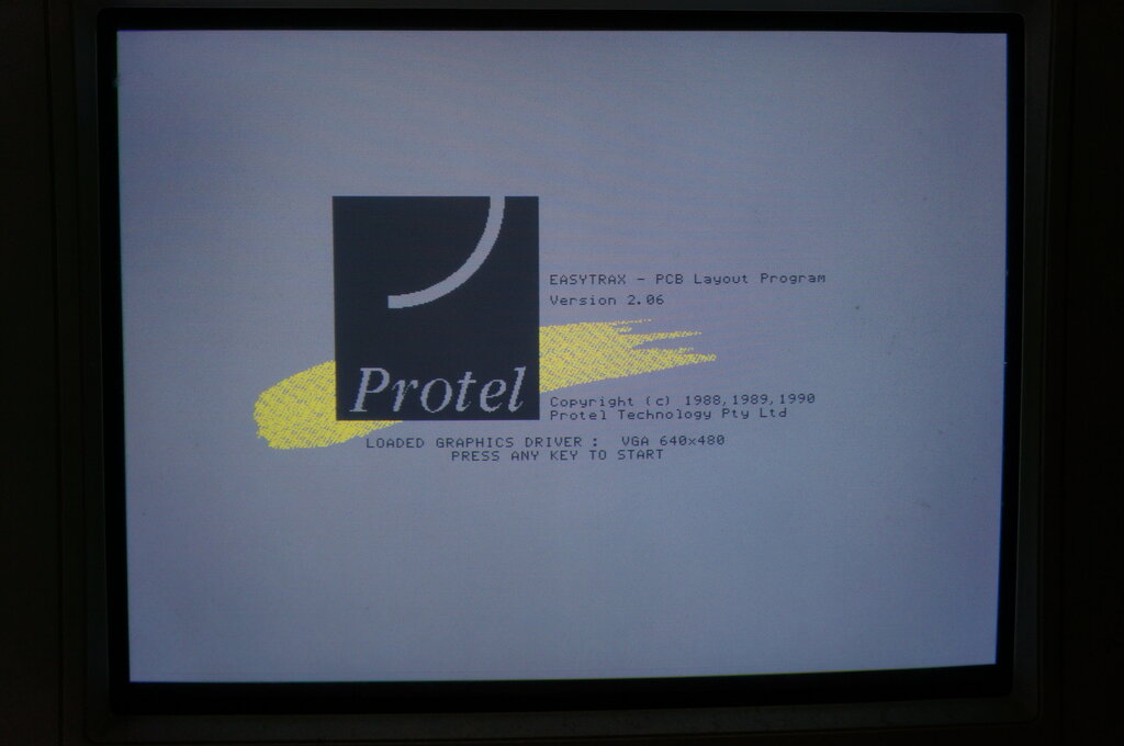
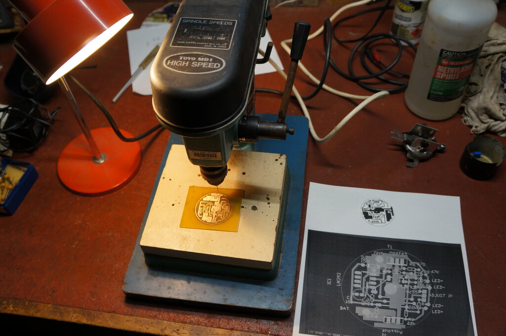
PCB design for the Model T Ford voltage regulator. Computer is a
386DX40.
Once you've done the artwork and saved it, it's ready to be printed. Close Easyedit by quitting to DOS, and open Easyplot.
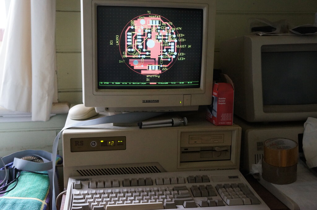
Next, select 'Options' and you'll get this screen:
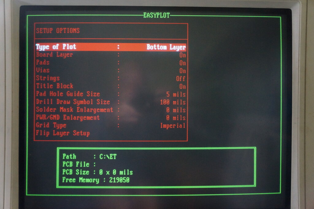
Set Pad Hole Guide Size to 5 mils (or appropriate value).
For the pad holes to be visible in the
printout, you'll have to set a suitable value here; 5 mils is a good starting
point. Once set, press ESC to return to the menu. ESC again to return to
the main menu:
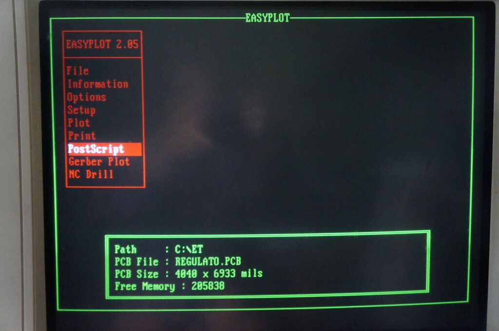
Note that file has been loaded.
Select PostScript and ENTER
The next screen you see after pressing
'Enter' is this:
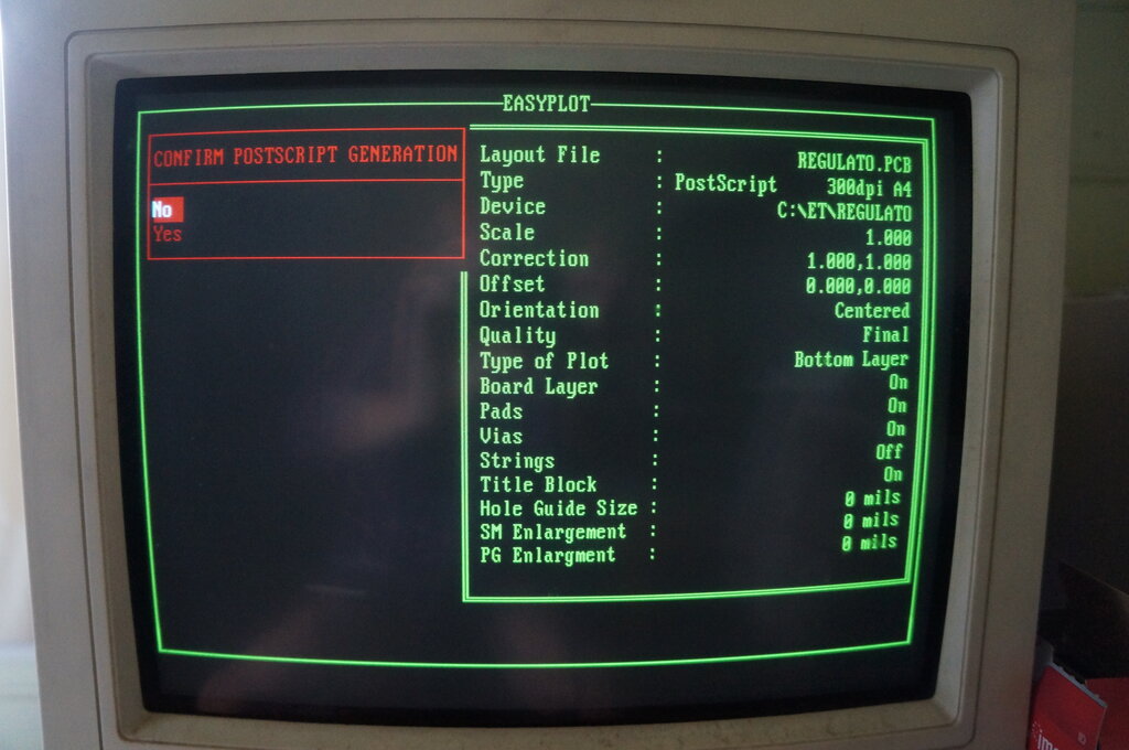
Settings for the PostScript file.
Make sure 'Quality' is 'Final', and 'Bottom Layer' is selected as per the screen shot. If not, go to 'Setup' as per the previous screen, and select 'PostScript' to alter the settings. ESC to leave the setup.
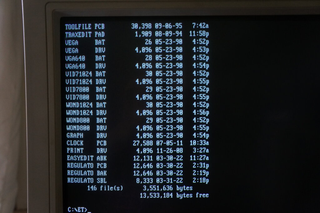
The file of interest is "REGULATO SBL"
The Post Script file, in this case REGULATO.SBL,
is now transferred to a modern Windows computer, with a functional browser
and internet connection. If you're into ancient computers, you'll know
of various ways to do this. I use a floppy disc, but I could also boot
the 386 up in Windows For Workgroups 3.11, and send it via the network.
Change the file extension by renaming
the file; in this case to REGULATO.PS
Go to the file conversion site https://www.zamzar.com/
and load the .PS file. Select output as PDF. Once converted, open the file,
and view your artwork. Print it out to ensure it looks correct, and is
the right size.
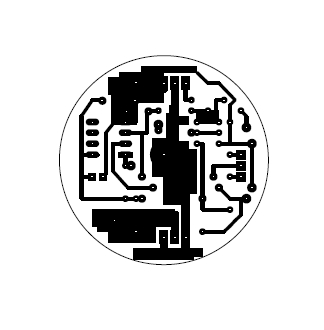
Screenshot of the resultant PDF.
Once satisfied the artwork is correct, it's now ready for printing on glossy paper.
Printing the Artwork.
Use glossy paper from a magazine. This
acts as the transfer medium, and the gloss prevents the toner being absorbed
into the paper. Instead, it all transfers to the board.
Preferably use the separate input tray
of the printer to minimise the path the paper has to travel through.
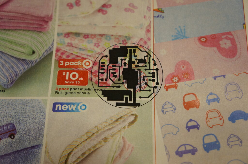
Artwork printed on glossy paper.
Preparing the PCB.
Clean the PCB with a Scotchbrite, or similar
abrasive cleaning pad, to make it shiny. Rinse and dry. A heatgun or hairdryer
speeds up the drying.
The paper is now attached to the PCB so
the artwork faces the copper (obviously). Ordinary tape can be used to
secure it - you don't want it to move.
Warm up the iron. I found it best to use fibreglass PCB. The phenolic kind can delaminate with the heat.
Place the PCB on a heat resisting surface. Since the glossy paper will start to stick to things, place a sheet of normal paper between the iron and glossy paper. Heat the glossy paper with an even downward pressure for about a minute and move the iron around evenly.
Let it cool down for a few minutes and place in water. After another few minutes, the paper will be weakened and can be carefully removed by rubbing with the fingers. Don't use anything sharp or the toner may come off also.
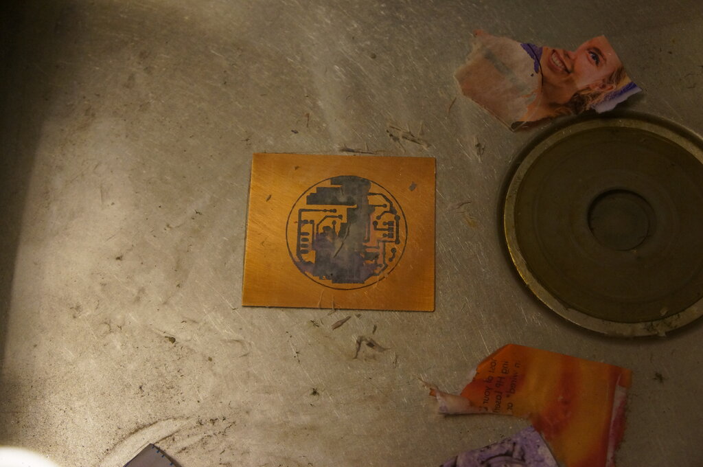
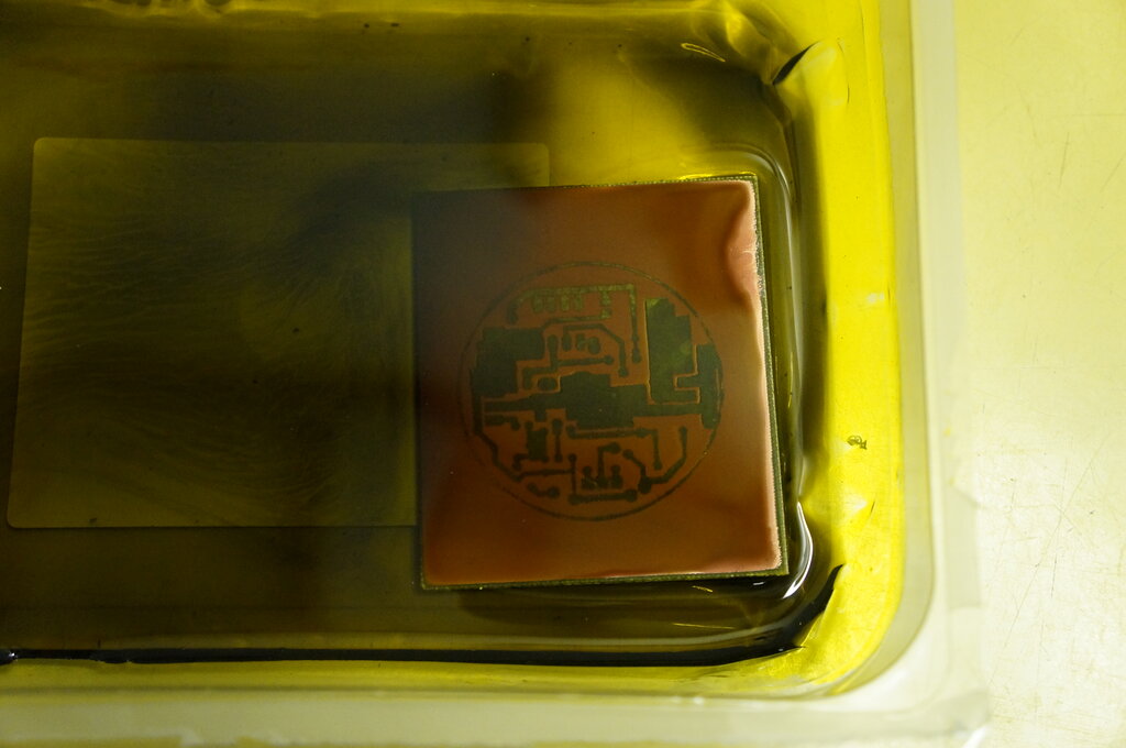
Dissolving the paper away.
Once you've removed the paper as best as possible this way, it's ready for the ferric chloride. Use a plastic or glass container. Agitate the ferric chloride so the copper falls off the board as it dissolves. A very rough guide is to allow about 20 mins in room temperature for the etching to take place. It is assumed one is aware of the corrosive qualities and dangers, etc.
The ferric chloride can be reused, so don't dispose of it after etching.
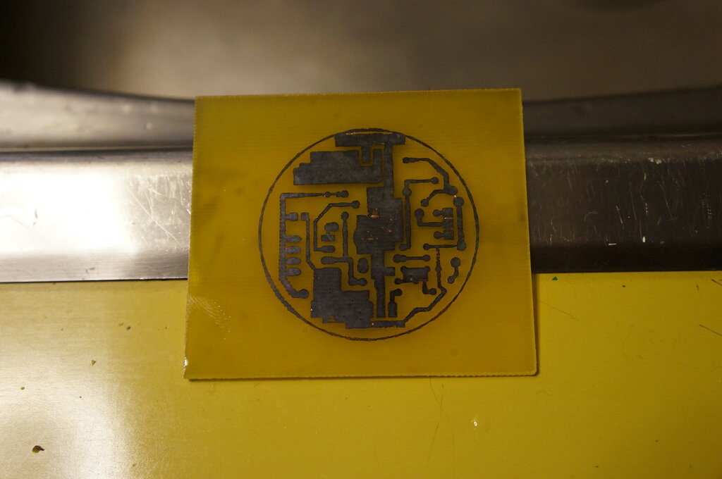
Once the copper is etched, just the tracks are left.
The toner is then removed with acetone. Next, the board is drilled.
Toner cleaned off and board ready for drilling.
It is a good idea to lightly spray the
track side of the board with plastic coating or circuit board lacquer made
for the purpose. This prevents the copper tarnishing.
The board is then ready for component
installation.
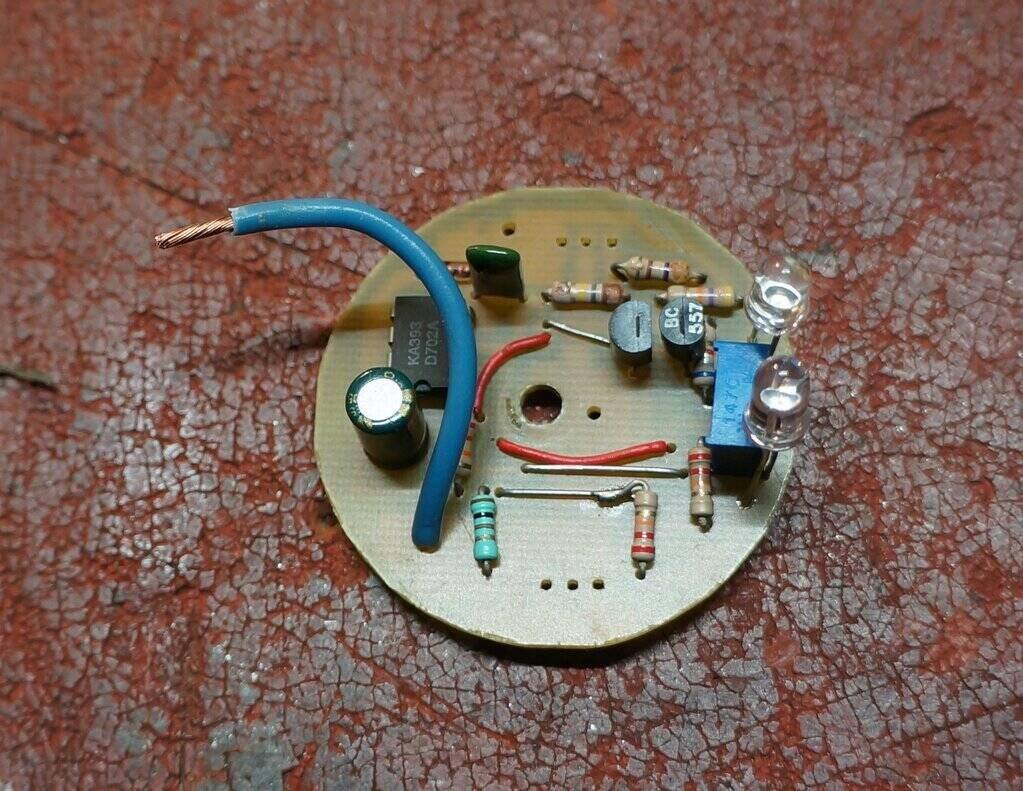
Parts mounted. As you can see, at least one mistake was made with
the artwork - the pad was left out for one of the 22k resistors. Such often
happens with the first board design. Also, the resistor length should have
been another size up.