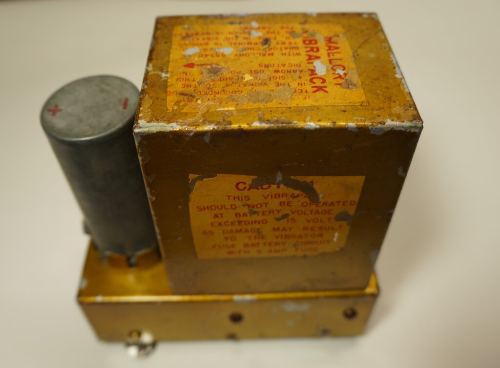
"Caution this vibrapack should not be operated at battery voltage exceeding 15 volts as damage may result to the vibrator. Fuse battery circuit with 5 amp fuse"
"Caution this vibrapack should not be operated at battery voltage
exceeding 15 volts as damage may result to the vibrator. Fuse battery circuit
with 5 amp fuse"
This Vibrapack came to me via a very kind
reader from the U.S, Craig from N.C., who I've mentioned in the article
on the G368
Vibrapack. I had seen this Vibrapack advertised on eBay, and so had
Craig, who thought it would be an ideal spare for his diving amplifier,
and so he purchased it. Unfortunately, although it had the same vibrator,
it was physically too tall to fit, and so it was offered to me - which
of course I could not refuse. Not all was wasted however, because Craig
was able to keep the vibrator as a spare.
Once it arrived, there a few very interesting
things I noticed. First, unlike all the other Vibrapacks I have seen, this
one has no model number.
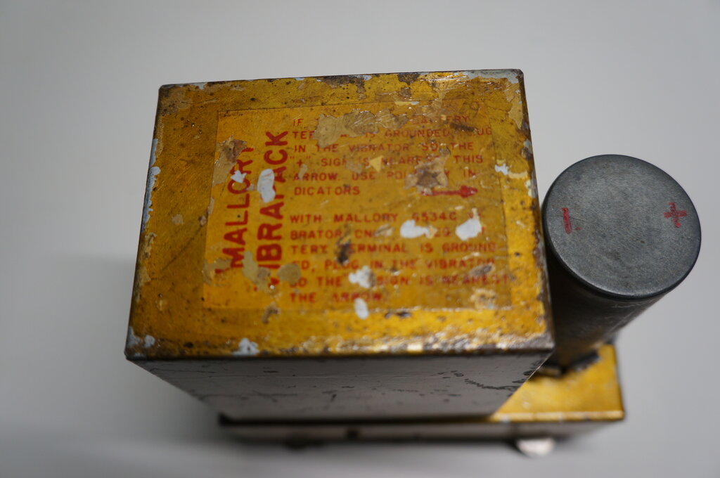
No model number; just "Mallory Vibrapack".
Quite clearly, it was purpose built for
a specific manufacturer. Secondly, the whole unit was tropicalised. That
is, it was painted in varnish to prevent fungus growth in tropical areas,
or to slow down corrosion in marine environments.
Unlike all the other Vibrapacks I have
seen, the labelling is on decals rather than being printed directly on
the transformer case.
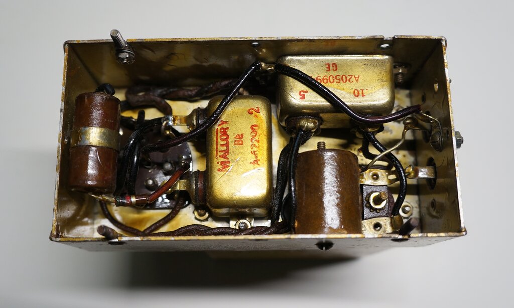
Underneath the chassis, everything is tropicalised here too.
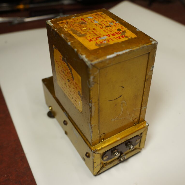
Terminals for 12V, B+ and earth.
At some time in its life, the Vibrapack
had been removed from its original equipment and re-used somewhere else.
Rubber strips had been glued onto the base. The original rubber grommets
to isolate the four mounting studs had been replaced with generic steel
washers.
One of the mounting studs was missing
altogether, and one of the others had at some time had its mounting rivet
broken, since it had been replaced with a nut and bolt. Also, shake proof
washers had been placed under the terminal screws.
The AC from the transformer secondary is
rectified by the secondary contacts on the vibrator. This eliminates the
use of a rectifier valve with its inferior efficiency, and makes the power
supply more compact. Perhaps not so well known is that a synchronous circuit
is actually the best way to operate a vibrator. This is because the timing
circuit operates under the most effective conditions. This comes about
because with the secondary contacts making connection after the primary
contacts, and disconnecting before they open, the timing circuit is not
actually exposed to, and thus loaded down by, the loading on the DC output.
When a conventional rectifier is used, current is drawn as soon as the
voltage rises to above that of the first B+ filter capacitor.
In other words, current is minimal when
the vibrator contacts are actually opening and closing. Most of the current
flows only after the contacts have closed and before they open again.
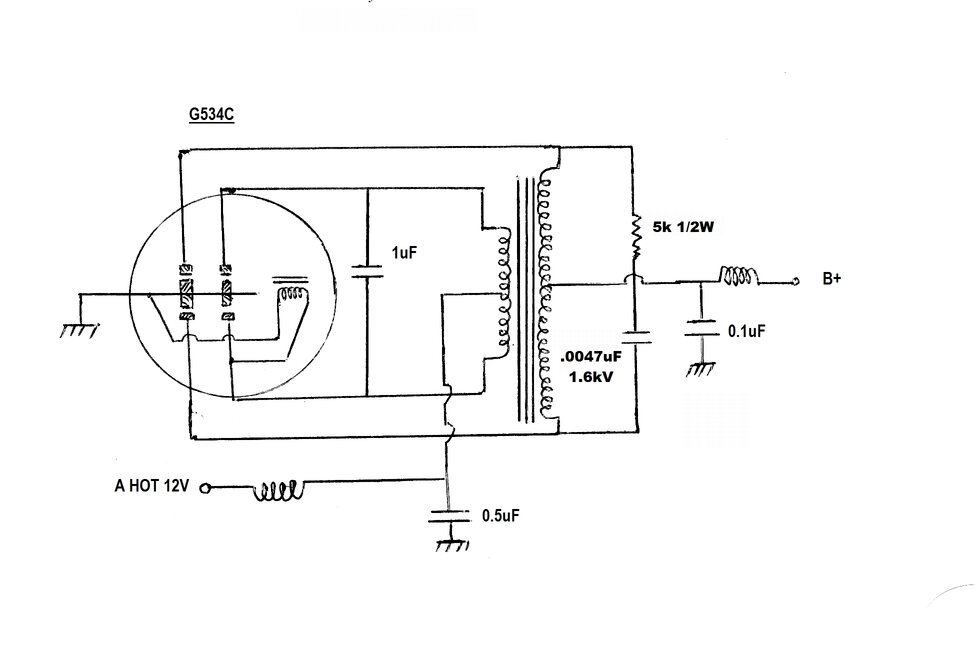
The vibrator can be plugged in one of two ways, both 180 degrees apart. This allows correct output polarity for both positive and negative earthed 12V input. The operation of the reversible base has been described here. As the labelling states, the "-" sign is adjacent to the arrow when the 12V supply is negatively earthed. When a positive earth supply is used, the vibrator is inserted so the "+" sign is adjacent to the arrow. It's a very clever scheme which does away with resoldering wires or changing links.
Filtering of the B+ output is minimal, with only a 0.1uF condenser and RF choke. It is expected that the apparatus with which the Vibrapack is used contains the usual electrolytic filter capacitors and possibly a choke as well. The 12V input filtering is also minimal, with only a high current RF choke and a 0.5uF bypass condenser. It would appear that like the G368, this was used with non radio circuitry, such as an audio amplifier.
Vibrator.
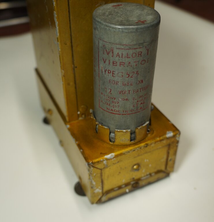
First thing to do was to find a suitable
vibrator in my collection. It uses the standard Mallory reversible five
pin base, but needed to be 12V. The label says it should be type G534C.
The "G" prefix with Mallory vibrators indicates 12V, and the "C" suffix
indicates it is hermetically sealed. Seeing as the rest of the unit was
tropicalised, a hermetically sealed vibrator is to be expected.
I didn't have a G534C, but I did have a
G525. This is 12V and has the required five pin reversible base. It is
not hermetically sealed, but since I won't be going anywhere tropical,
this is not important - a standard vibrator will do. This particular G525
had been opened some time in the past, suggesting it had at some point
no longer started, and required contact adjustment.
As it was, it did start, but only with
a sudden application of 12V. Testing on the vibrator test panel showed
the duty cycle was a bit low. Obviously, the contact gap on the primary
contacts had increased too much.
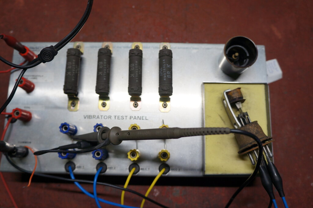
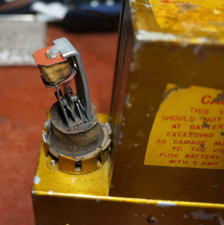
Testing the vibrator for duty cycle and contact condition.
Adjusting the contacts was easily done. Mallory vibrators are among the best of the shunt drive types, and easy to get going. The insulators are solid pieces which don't allow adjustment, so the contact arms are adjusted instead. In this instance, the side arms are quite rigid, and it's a very simple matter to adjust the contacts on the reed instead. Adjustment required was minor, and an excellent waveform resulted. The contacts did not need any cleaning.
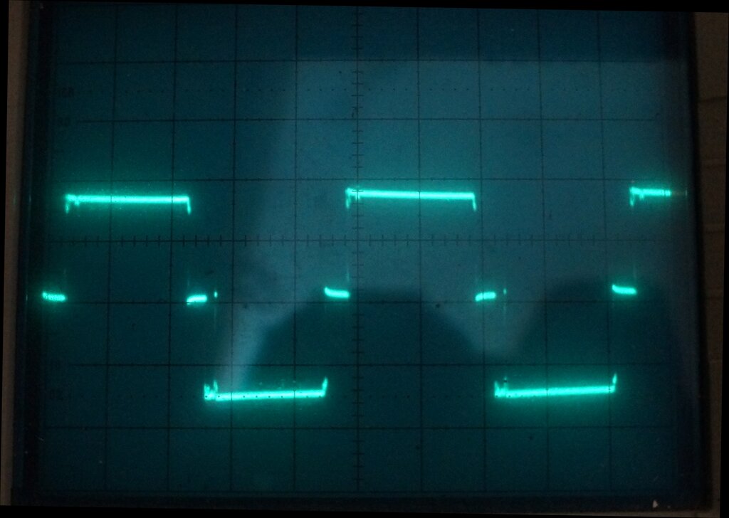
Duty cycle is 79%.
A slight further adjustment on one of the
primary contacts was necessary to obtain the required 80% duty cycle. The
secondary contacts did not need any adjustment. They're adjusted for a
few percent less duty cycle, so that they open and close before and after
the primary contacts.
With the vibrator tested in the unit,
an excellent primary waveform was obtained.
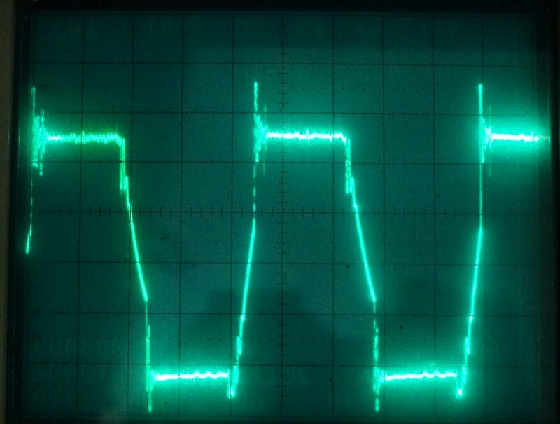
Waveform has an excellent slope, which indicates the duty cycle
is correct, as is the timing circuit.
Seeing as the vibrator was open, I plugged it into the Vibrapack to see if there was any contact sparking. There was none, and once again it seems Mallory has got the design right. The vibrator will last a very long time.
No sparking on the contacts.
With the vibrator working well, it was put back into the can. For the crimped can type of vibrator construction, I now secure the mechanism back in the can by soldering a loop of tinned copper wire around the base as shown below. Before doing so, the can edge has to be flattened out, using a brass tool made for the purpose.
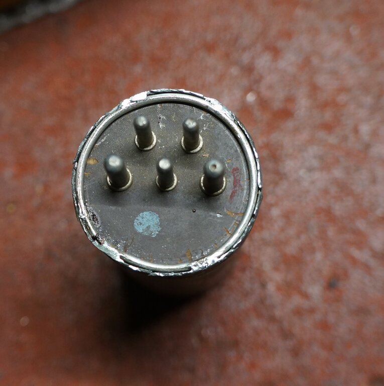
Can closed up. Note the reversible base.
Once back together, the jagged edge is
filed smooth.
I've described this method of reassembling
crimped can vibrators in the Ferrocart
article. It is far neater than simply bending the can back over. It
also has the advantage of the vibrator being easily opened in the future,
without further disfiguration, if it needs to be.
G525 vibrator installed.
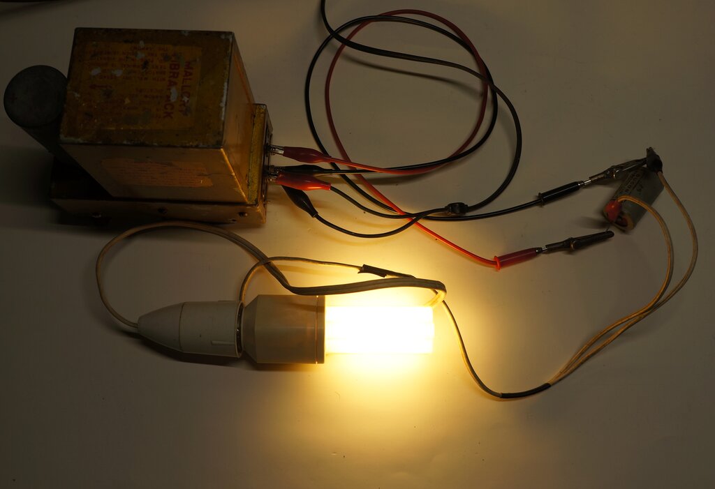
Vibrapack operating a 240V 11W compact fluoro. 16uF electrolytic
filters the B+ output.
With the B+ output filtered with a 16uF
electrolytic condenser, and loaded with an 11W compact fluorescent lamp,
output voltage was around 310V. This would suggest a 300V design centre.
The output current rating is anyone's guess, but is likely to be around
80mA, or possibly even 100mA, which is standard for many other Vibrapacks.
On that note, this Vibrapack would not
have been suitable for the Guided Radio Corporation 957 diving amplifier,
in view of the much higher B+ output voltage.
Should anyone be horrified at the application
of 310V DC to a 240V AC compact fluoro, remember than the compact fluoro
actually operates from DC, obtained by rectifying the mains. When the 240V
AC mains is rectified, the filter capacitor charges to 340V, since this
is the peak of a 240V rms sine wave.
Since the fuse is recommended to be 5A,
this suggests a current draw of about 2A at 12V, which is 24W. At 300V,
that allows for 80mA. Fuses in vibrator power supplies like this tend to
be rated at about double the normal current draw. It makes for more reliable
fusing, but at the same time will protect against short circuits or severe
overloads.
Overall, it's a very useful Vibrapack,
since 12V supplies are far more common than 6V in the modern day, and the
B+ output suits common 250V valves and circuitry. One could of course also
use it to operate 240V LED bulbs and compact fluorescent lamps from a car
battery.