No doubt a Chinese take off of the Panasonic
name, this kit radio is widely available on eBay for less than $10, including
postage. Seeing as it's designed around clones of my two favourite IC's,
and is not the usual boring old superhet, I had to buy one.
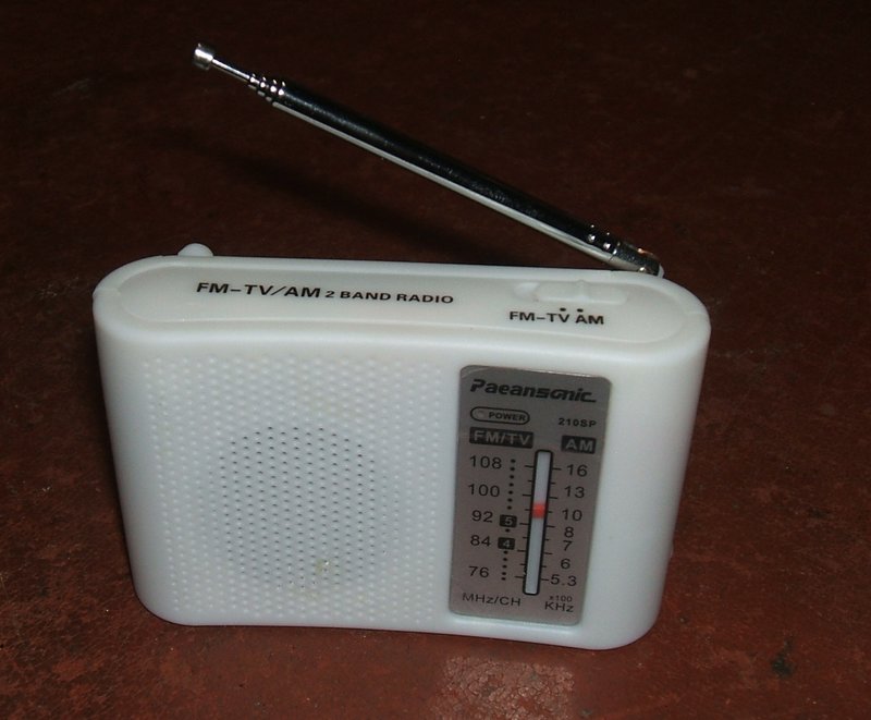
It's a cute little set approx. 100mm x
65mm and 25mm thick. The AM section is TRF using the TA7642 IC which has
been described here.
The FM section uses a CD9088, a clone of the Philips TDA7088 which
is described here.
It is a superhet but uses a novel IF amplifier with no tuned circuits.
Audio amplification is done with a TDA2822. The set runs on 3V from two
AA cells. An interesting aspect of design is that it covers the Japanese
FM band, with the lowest frequency being 76MHz. However, it also claims
TV sound reception; with channels 4 and 5 shown on the dial. This is an
out of date gimmick, since TV stations broadcasting FM sound are no longer
extant with the demise of analog TV. But that's not the complete story.
Australia was about the only country in the world to transmit TV in the
FM band with channels 3,4, and 5. The "4" and "5" shown on this dial are
not anywhere the shown frequencies of the Australian channels. It is true
that some radios did actually allow TV sound reception, but these had the
band switching to allow it. This set certainly doesn't - as do other Chinese
radios of similar design.
What Comes in the Kit?
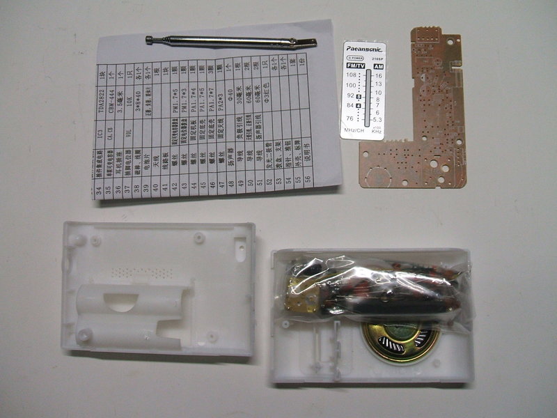
The entire kit comes in a small bubble wrap package, with all the parts inside the radio casing. A two sided piece of A4 paper shows the circuit diagram, parts list, and PCB layout.
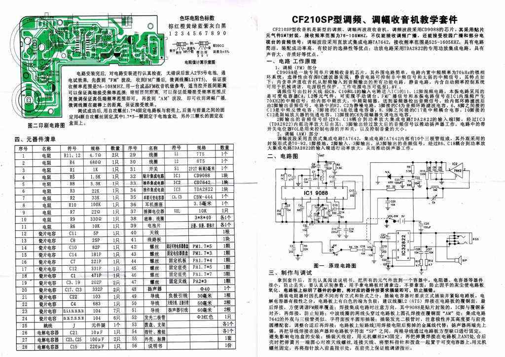
Since I can't read Chinese, most of the instructions are not of use. I can make out that a technical description of how the set works is provided - but as I'm already familiar with that, it isn't essential reading.
FM Reception.
This is based around a CD9088 IC, a clone
of the now obsolete Philips TDA7088. This in turn was based on the TDA7000.
The differences are that the TDA7088 is surface mount and incorporates
search tuning, although it can be used with a mechanical variable capacitor
for tuning. The SC1088 is another Chinese clone, and the data for this
IC appears to have been taken directly from Philips.
These IC's have been described in detail
here,
but briefly their feature is the use of an IF amplifier with no coils or
ceramic filters. This is achieved by the use of a 70KHz IF, which allows
"audio" op-amp Sallen-Key filter circuits to be used. To prevent distortion
due to the 75KHz deviation of the FM signal, a frequency locked loop circuit
compresses the deviation, by modulating the local oscillator with the audio
signal. It is compressed down to 15KHz deviation by this means.
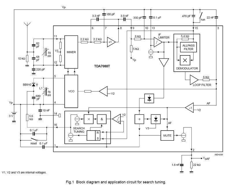
TDA7088 block diagram, and how it is configured for variable capacitor
tuning.
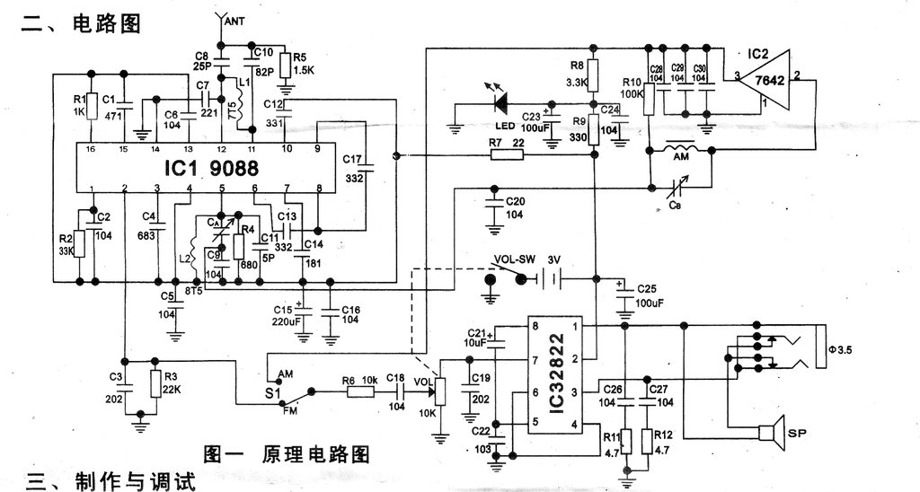
In the circuit for the 210SP, the connections and components used with search tuning are of course not used. The 'run' (search) and 'reset' switches are not used, nor is the tuning voltage from pin 16 and associated varicap diode. Two notable differences between this IC and the TDA7000 is the inclusion of two resistors; one across the oscillator tuned circuit; 1.2K in the TDA7088 application circuit, and across the aerial input; 10K. Their purpose is not entirely clear. Assuming the mixer input is 700 ohms like the TDA7000, a 10K resistor won't have much affect. My guess is it's actually a static discharge resistor to protect the input if the aerial is touched by someone who has accumulated a static charge. As for the tuned circuit, I cannot provide an explanation as to why it would need to be damped.
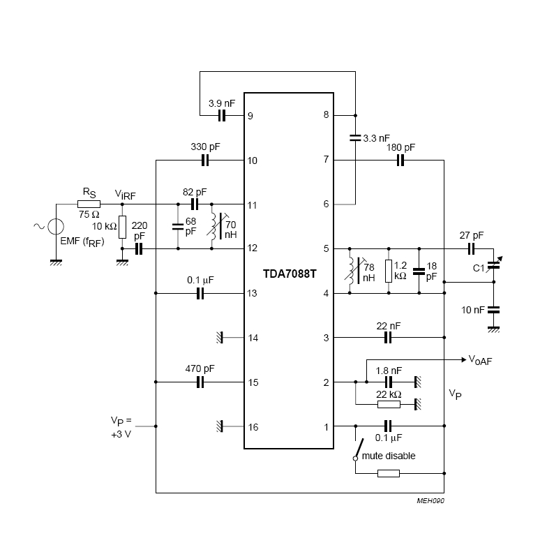
The input circuit is fixed and broadly
tuned. Thus, only the local oscillator requires tuning which simplifies
the circuit. It appears the 210SP has the mute disabled by the 33K resistor
at pin 1. The value of this resistor is not shown on the TDA7088 circuit.
Audio output is at pin 2. The associated
capacitor provides de-emphasis.
AM Reception.
A conventional TA7642 circuit is used
here. It is a TRF IC with detector and AGC. That is, all the gain is at
the receiving frequency. This IC has its origins in the Ferranti ZN414,
but is not an identical clone, although it is considered a drop in replacement.
A high brightness LED regulates the supply voltage to about 1.8V. This
is important since this IC is very sensitive to supply voltage. In some
circuits this is user adjustable to obtain the best operating conditions,
but in commercially made receivers like this, it's fixed. The load resistor
(3.3K) is somewhat higher than used for the ZN414/YS414/MK484, but also
the supply voltage is slightly higher than used with the latter.
Signal pick up is from a small ferrite
loopstick, and is tuned with a common variable capacitor as shared with
the FM circuit. The three paralleled 0.1uF capacitors on the output of
the TA7642 was obviously done because a single 0.33uF would be too big
to physically fit.
A possible point of confusion is the connection
between the AM and FM sections. Note that the TA7642 AGC line, bypassed
by C20 connects into the FM tuned circuit. This in actual fact is merely
representing the variable capacitor having a common earth connection between
the AM and FM sections. The TA7642 AGC voltage is not loaded down by anything
since it is only running into CA and C9.
Audio Output.
This is based around a TDA2822 IC. This
is a dual power amplifier designed for low voltage. it can be used as two
separate amplifiers, as in a stereo application. But, in this instance
it's being used in bridge configuration which allows a greater output with
only 3V supply. At this voltage it provides about 300mW output into 4R.
The speaker in the 210SP is 8R, so power will be less.
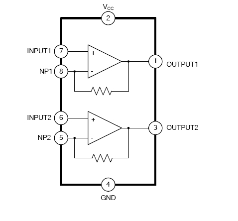
Audio input comes into pin 7 and an amplified
version appears at pin 1 which feeds one side of the speaker. The negative
feedback voltage developed which appears at pin 8 is connected into pin
5. The input of the second amplifier is earthed. Note that as the non inverting
inputs of both amplifiers are connected together, it means the output of
the second amplifier will be out of phase with the first. Hence, twice
the output voltage is produced. The output is balanced, hence tow Zobel
networks for stability (the 4.7R and 0.1uf). It must be remembered that
the "ring" connection of the headphone socket is therefore not earthed
as would normally be the case.
A peculiar aspect of design is the volume
control connection. The 10K potentiometer is wired backwards so that it
progressively shorts out the incoming audio signal, rather than acting
as a normal voltage divider. However, it appears the TDA2822 likes a 10K
fixed resistor at its input, and it's easier to use the pot to take its
place. Voltage divider action does still take place by virtue of R6.
AM or FM is selected simply by switching
between the outputs of the two receiver IC's. Both AM and FM receivers
are operating all the time despite the audio from only of them being used.
One could argue that battery life might
be extended slightly by switching off the unused section. The low impedance
of the audio circuitry prevents any cross talk between the two receivers
being heard.
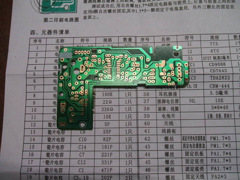
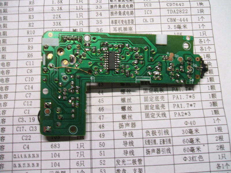
Bare PCB ready for components.
First thing was to deal with the surface mount CD9088. This was actually very easy to solder on the PCB, but a fine tip soldering iron, and fine solder wire help immensely. The trick is to secure the IC before the first pin is soldered. Once this is done, the IC stays in position while the other pins are soldered. Any mistakes can be cleaned up with solder wick.
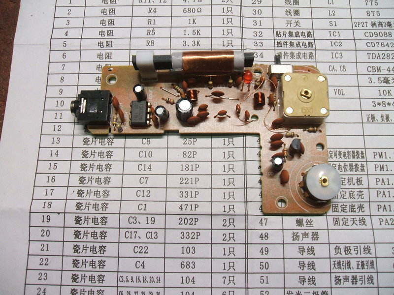
All components installed in PCB.
It only took a few hours to install all
the parts. Despite the Chinese instructions, there's no problems since
the board is labelled with the component values. One link has to be installed,
and this can be just a lead off cut.
The ferrite loopstick bracket is very
loose unless secured with glue. I used hot melt for this. Also, the ferrite
bar is loose in the bracket unless packed up with something; I used cardboard
and then more glue.
Component side of PCB.
Installing the LED takes some care, since
it has to line up with the front part of the case. It's best to place the
board in situ, push the LED out as far as it will go, and then solder in
position. Remember, long lead is positive.
The case comes next; the battery contacts,
speaker, and aerial have to be installed.
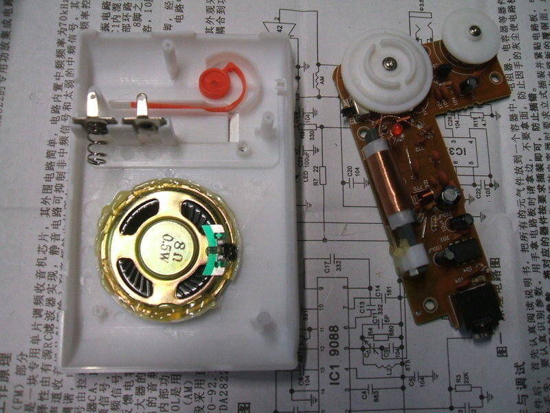
The dial pointer band had not yet been screwed under the tuning
capacitor knob screw.
I used hot melt glue to secure the speaker,
since it's quick and can be removed if necessary. The speaker is a mylar
type, much like a large headphone driver. Short lengths of solid core wire
are provided to connect the speaker, battery, and aerial.
The dial mechanism is crude, but typical
of cheap radios. It relies on a plastic band attached to the tuning knob.
As the knob is rotated, the band unwinds, or winds in, moving the pointer
across the scale.
Installing the aerial required some filing
of the slot in the back of the case. This was so the aerial mounting point
would be flush against the back. The dial scale is adhesive and simply
sticks on the front.
Getting the PCB into the case requires a bit of dexterity. The AM/FM switch knob is best left until the PCB is in position. The PCB is held to the front of the case by one screw between the tuning capacitor and volume control. When the back is screwed on, this provides more securing points. It's necessary for the battery contact lugs to be bent over for the back to fit on.
At this point it can be tested. For the
AM section, it's only necessary to adjust the relevant trimmer to set the
highest frequency. The AM trimmer is closest to the edge of the PCB.
The FM alignment took a bit more work.
I found it necessary to expand the oscillator coil slightly to get 108MHz
reception. Tuning the FM band is tricky since only half the scale is actually
used for the 88-108MHz part. Again, adjusting the trimmer carefully will
set the upper frequency limit. I found, however, that the lower frequency
limit was 72MHz instead of 76MHz. It's possible that I could have got the
band coverage exactly right, but given the critical adjustment, I left
it. As it is, the dial calibration is reasonable for the 88-108MHz section.
AM.
It was deja-vu as far as selectivity was
concerned. Much like my initial use of the TA7642 in this
set. Again, the 50kW ABC stations on 576KHz and 702KHz (46km distant)
tend to dominate the dial unless the radio is rotated to null out their
signal. The weaker (and 58km away) 5kW commercial stations are receivable,
but just loud enough for entertainment level.
At a location near North Richmond, (43km
from the ABC stations, and 40km from the commercials) selectivity was even
worse. Except for 2GB (873KHz), it was virtually impossible to null out
the ABC stations.
I then tried the receiver at a location
on the Lower North Shore; 34km from the ABC transmitters at Liverpool,
and only about 13km from the commercials at Homebush. Here, things were
a lot better. It was possible to just get adequate selectivity between
all the stations. However, 2RPH (1224KHz) was not listenable. This station
is located halfway across Sydney at Prospect, and is directed at the western
suburbs (it's the old 2WS AM transmitter).
FM.
At home in the Blue Mountains, with line
of sight to Sydney's FM stations, it works a lot like other radios using
the TDA7000 or clones, except that the small aerial (25cm) limits sensitivity.
I'm not convinced the muting is disabled, even though there's a resistor
connected to pin 1 of the CD9088.
As mentioned before, tuning is critical
with the small hard to adjust knob, and only half the tuning scale is used.
At the location near North Richmond, only the local station 2VTR, and 2WS
could be received, and that was with the set only in certain positions.
However, this location does not quite have line of sight to the transmitters.
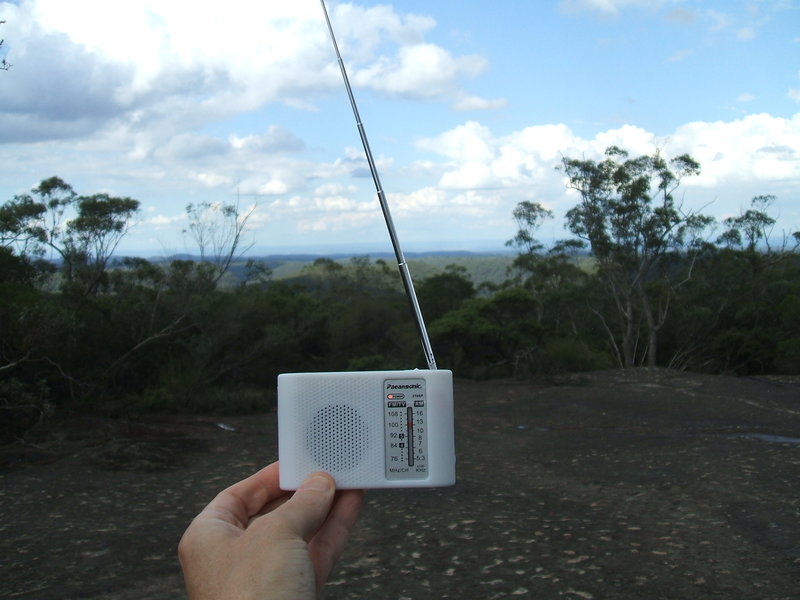
Out in the bush in the Blue Mountains, FM reception was as expected.
Reception of AM was poor for the commercial stations. Sydney is on the
horizon to the right.
Considering the 35mm speaker and 3V supply,
audio output is pretty good for what it is. Of course, there isn't much
bass response, but it's loud enough.
To sum up, it's a cute little radio, but
definitely not a DX receiver on AM or FM, and depending on your location,
the lack of AM selectivity may be problematic. Replacement of the TA7642
with a ZN414, YS414, or MK484 would improve the selectivity.