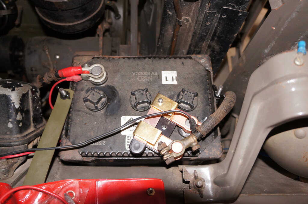
Voltage drop was too much.
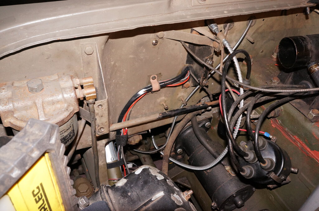
9/12/25: Installed battery isolator switch.
Voltage drop was too much.
I chose a knife switch type. The green
knob type of switch has proved to be unreliable. I've got one on the Model
T. Problem is the plastic melts and creates a gap between the fixed contact
and the screw down part. I've had to repair the one on the Model T once
already. The fact that the plastic melted means there's excessive voltage
drop.
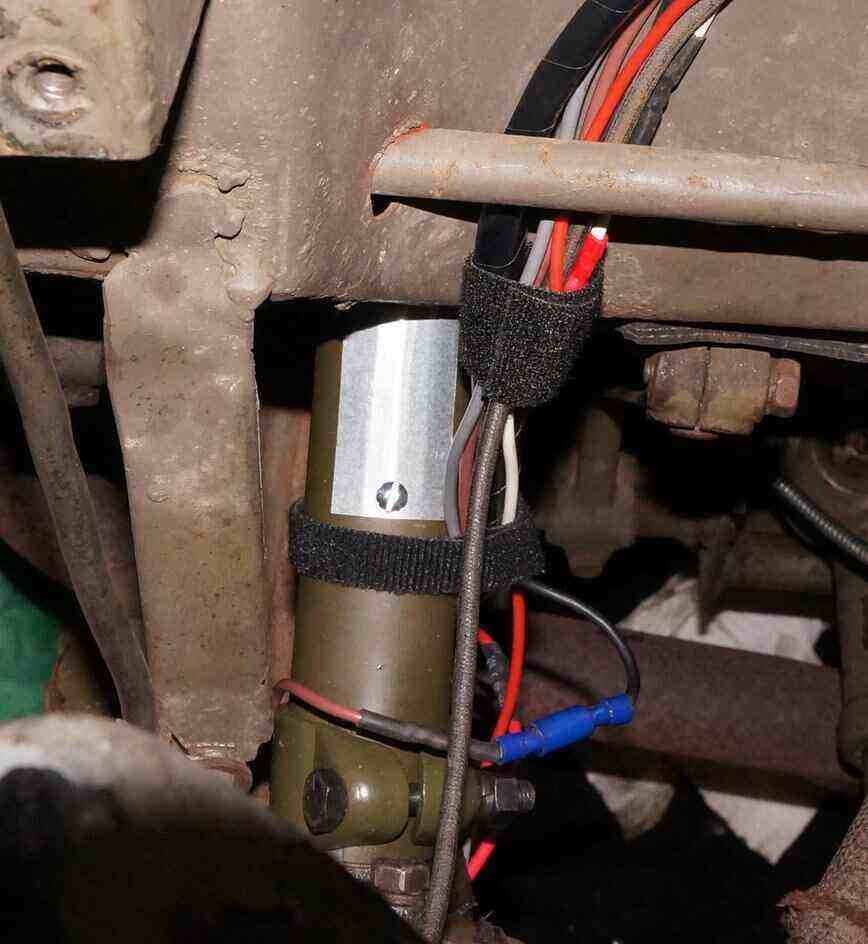
Unfortunately, while the knife switch
was simple to install, and doesn't have the problems of the other type,
it too had a voltage drop. This is to be expected of course. In this case
it was around 200mV while starting. That's 3% of the battery voltage, which
I felt was unacceptable.
In fact of all days, in the mid 30's,
the engine should have been very easy to crank, but as soon as I tried
it I noticed a slight drop in cranking speed. It would have started, but
there's no leeway for colder weather, etc. 3% might not sound like much,
but for a 6V system it's significant. I removed the switch, and cranking
speed was back to normal. I think I'll fit this switch to the Model T where
cranking current is less.
Fact is, the Jeep has survived all its
life without an isolator, and my main reason for installing it was to prevent
operation of horn and lights when parked unattended. Those functions can
be done with relay circuits.
10/12/25: Made up new bracket to support bimetallic spiral for the hot air bypass valve. There was a home-made bodge there which did not allow for correct operation of the bimetallic spiral.
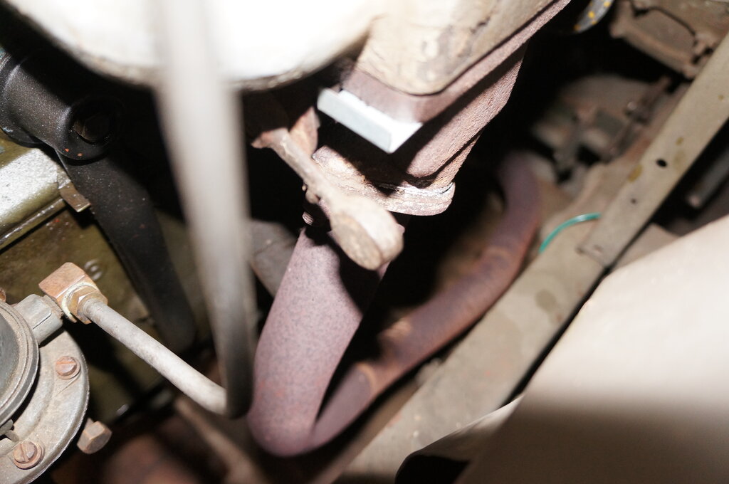
In cold position valve is open.
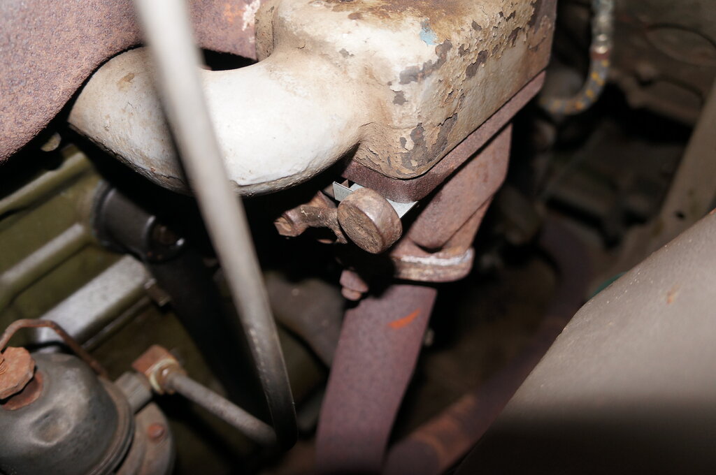
When hot, valve is closed.
The exhaust manifold opens to the underneath of the carburettor to help the fuel vaporise when started cold. There is a thermostatically operated valve which closes off this opening once warmed up. It is controlled by a bimetallic spiral. You can see a weight on the end of the lever - this keeps the valve open unless the bimetallic spiral is heated.
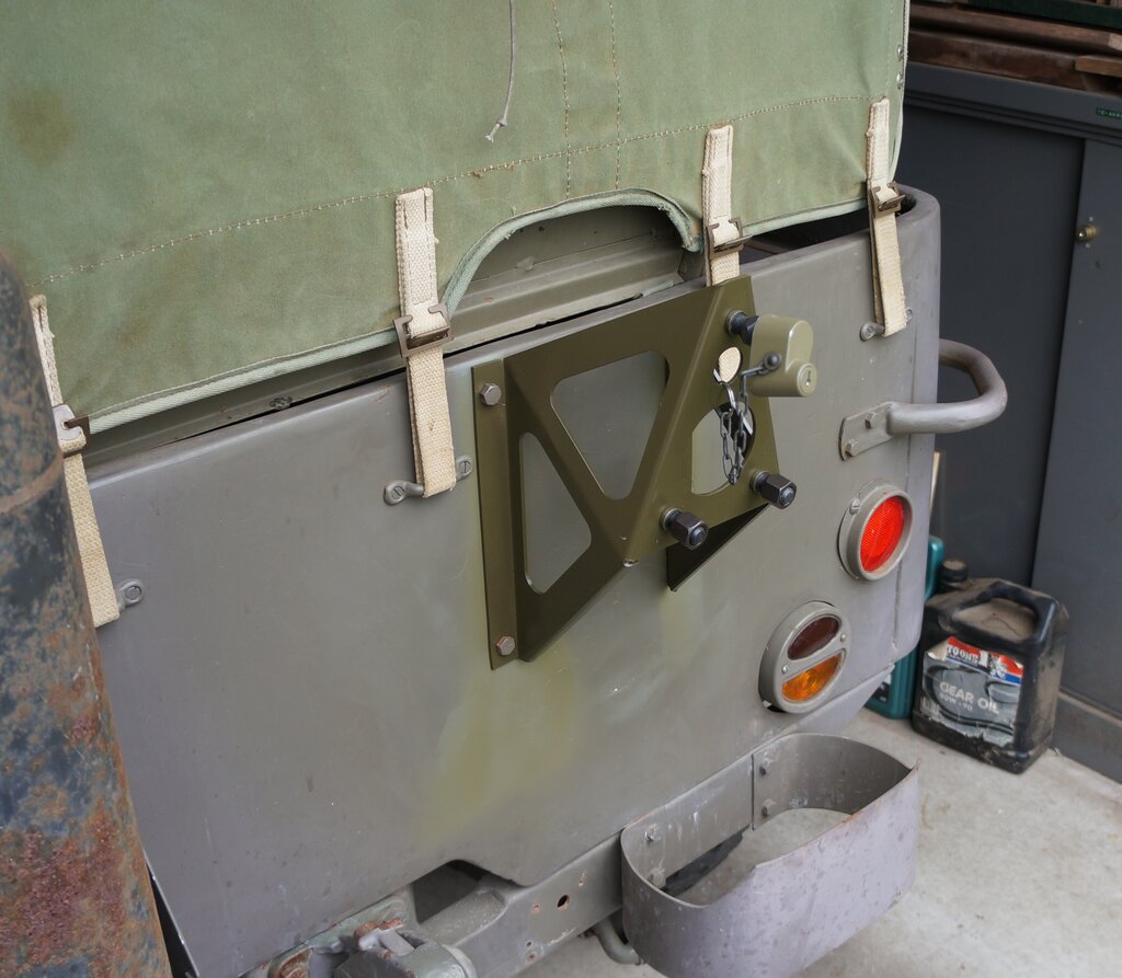
15/12/25: Install spare wheel lock. Conveniently, the key is the same as the toolboxes.
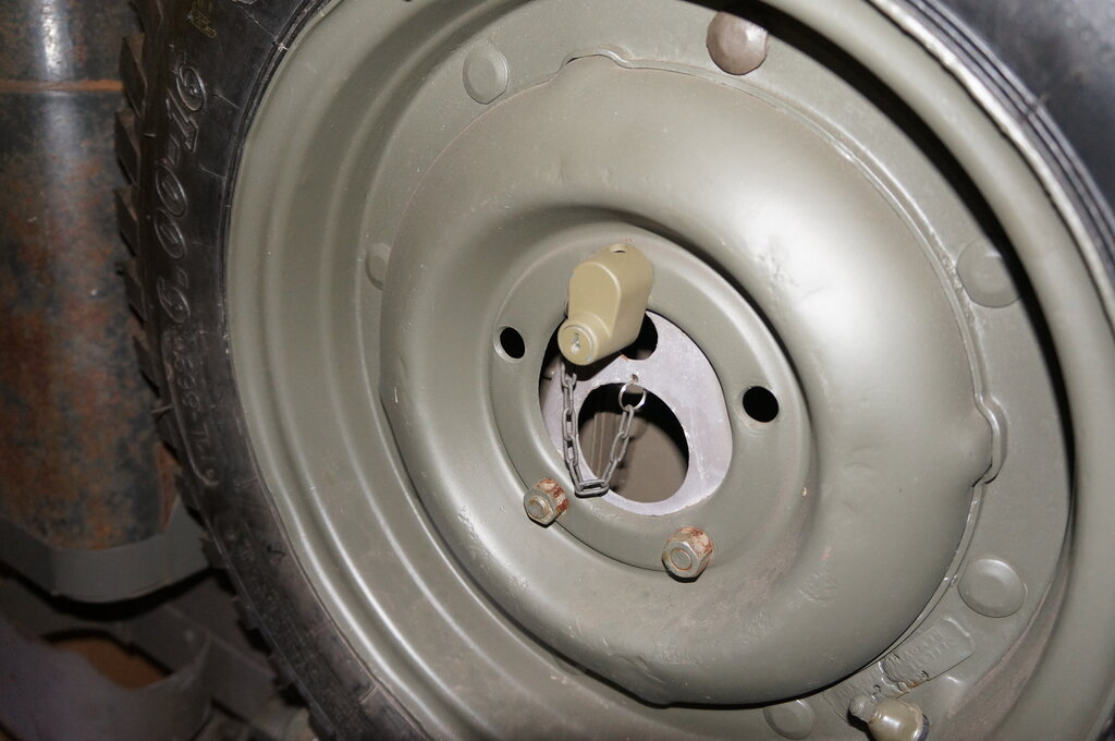
No idea if this is the correct way to attach the chain to the wheel
bracket.
17/12/25: Fire extinguisher: A repro bracket came with the parts, but alas the diameter it takes is 77mm. All the modern small 1kg type of fire extinguisher are about 80mm. I decided to adapt a modern extinguisher bracket, and make my own to mount it to the Jeep. For this, I made the three cross pieces which bolt onto the fender. Then made the vertical piece onto which the modern extinguisher bracket could be mounted. The mounting holes were identical, so I could fit the repro bracket if a 77mm diameter extinguisher ever appears.
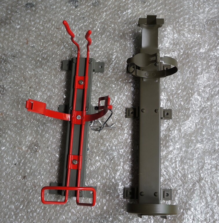
Made up my own bracket to take a modern extinguisher.
18/12/25: First test drive since registration. Covered almost 18 miles. Very happy with how it drives - except there is a problem with the gear shifting. Sometimes it is impossible to get it into 2nd gear. No problem moving the gear stick over the right side, but you just can't move it forward (2nd) or back (3rd). Once in 2nd, there was never any problem moving it between 2nd & 3rd. It seems from some forum comments there might be a plate on top of the transmission which wears.
Another thing I have to work out is how to get into 1st while under load going up a hill. One hill nearby can only just be done in 2nd, but would prefer 1st. I think I would need to be in 1st to ascend Scenic Hill or Brown's Gap Rd at Lithgow.20/12/25: Install fire extinguisher. Six holes are drilled into the fender - the diagram of where they go comes with the nuts and bolts supplied for this purpose. I painted the screw heads before installing. Four of them are hidden behind the shovel anyway.
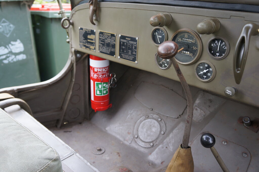
Four of the screws visible.
Incidentally, the screws are the same as for the side mirrors - useful to know when they don't turn up in the search on the parts suppliers sites.
22/12/25: Gearbox day today! I put
a question on the G503 forum about the sometimes difficult shifting into
2nd and 3rd. General thoughts are it's likely to be something in the tower
or the shifter plate.
Took off the floor cover for the first
time and was rather surprised to see a 1958 rebuild plate:
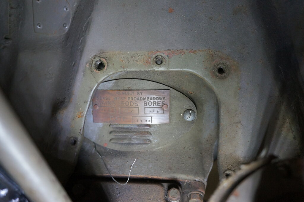
Rebuilt 3/3/58.
The fact the rebuild plate is on the bellhousing
makes me think the transmission was rebuilt at the same time. The piece
of wire emerging is a curiosity, and a potential worry. Is is holding something
precariously in position, which will never work again lest I disturb it?
But, onto the gearbox. First thing to
do was unscrew the gear stick ("cane" in Jeep parlance).
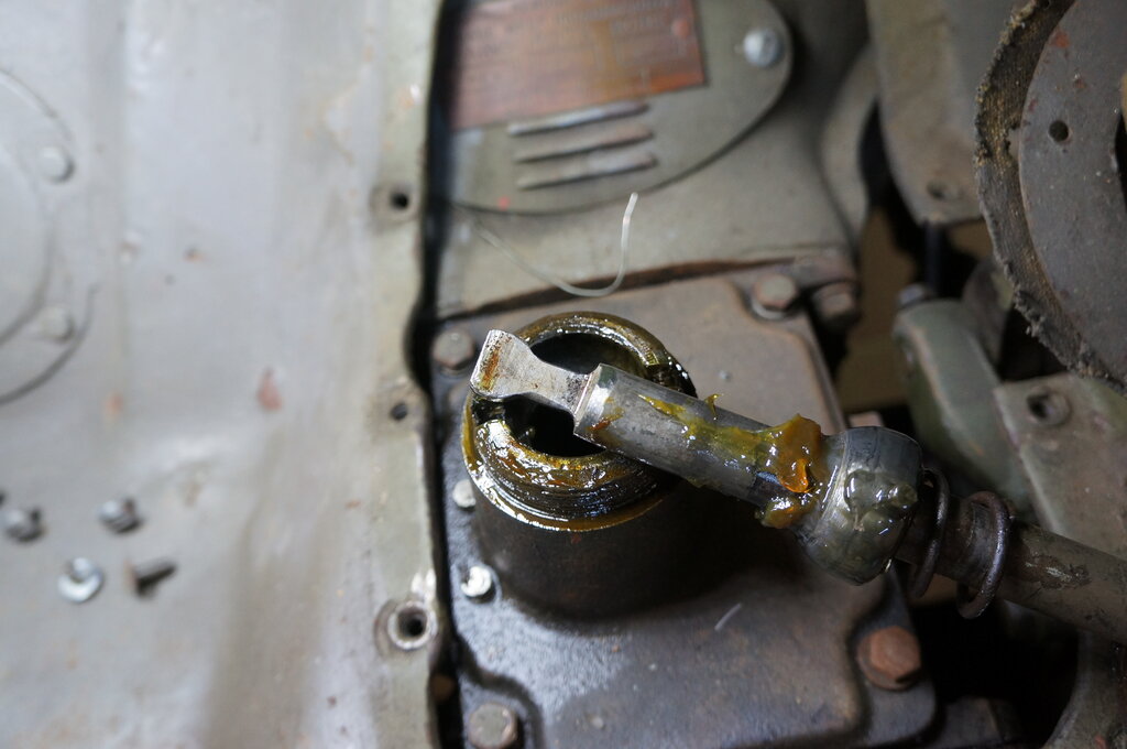
End of gear stick that engages in transmission.
Next to open the transmission. This is done by removing four 1/2" bolts on the top.
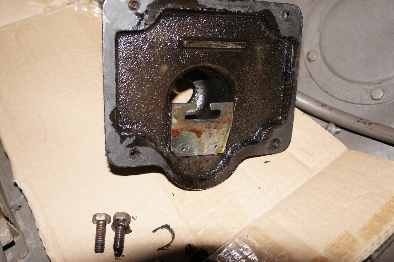
Gate plate under the cover.
Shifter plate in top of transmission. 2nd & 3rd on the left,
reverse and first on the right.
Side on view of shifter plate. It looks a bit rough, but then realised
someone has added the U shaped part to prevent the sides spreading from
the forces from the gear stick.
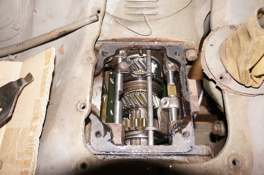
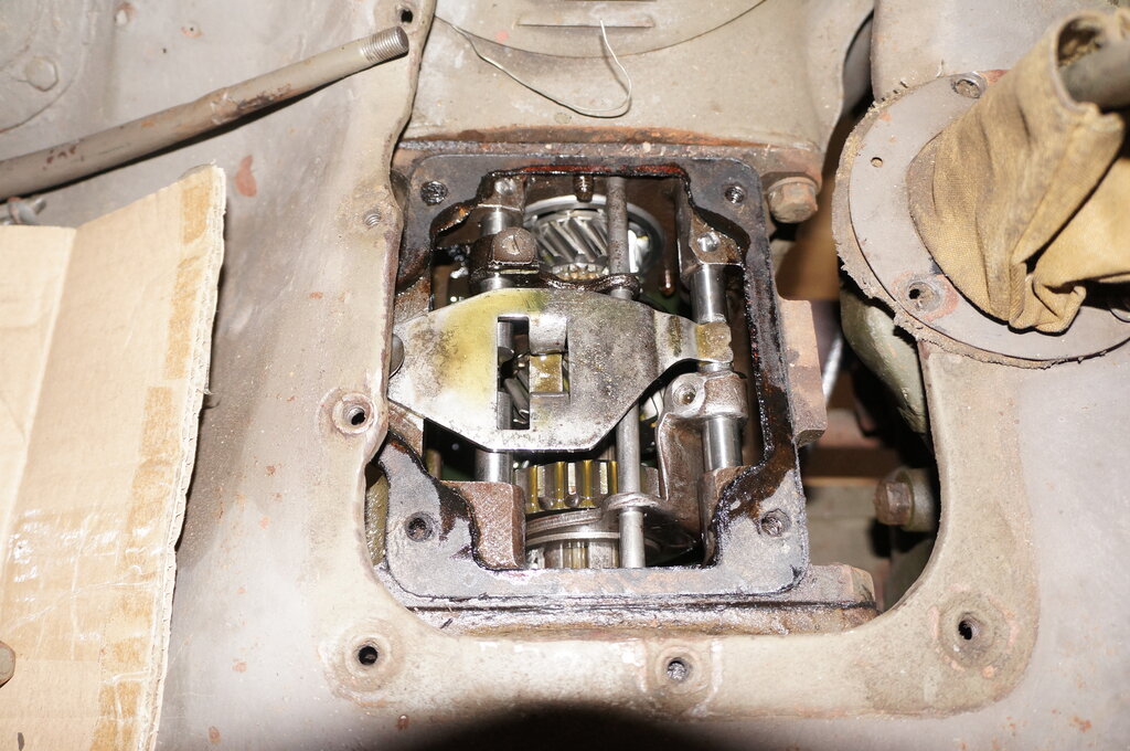
Inside transmission without shifter plate. Left rail is 3rd up,
2nd down. Right rail is reverse down, 1st up.
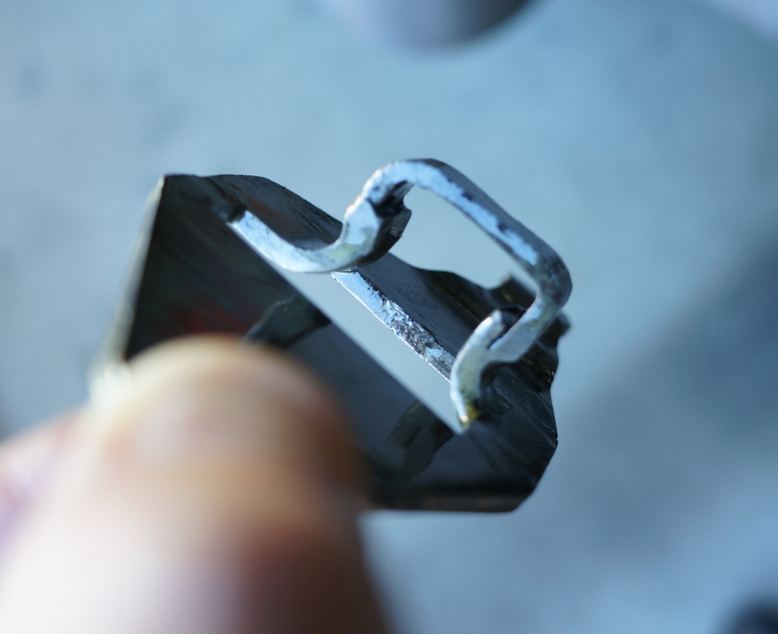
27/12/25: The guys on the forum haven't noticed anything unusual, except the slotted head screw which secured the shift fork to the shift rail. You can see it in the upper left of the photo above. Notice the screw for the fork in the lower right looks different. Apparently the screw should take a Bristol key (like the lower right). I took it out and found it's machined the same where it engages the shift rail, so highly unlikely to be the problem. So, I put it all back together.
Also found out the wire coming out of the clutch inspection cover is wrapped around the clutch release fork. I think that was to hold it in position during assembly. It is harmless and easier to leave it, so I did. I had to drop a light bulb down inside the bellhousing, and use a mirror to see it.

Look in the mirror for the piece of wire. It's wrapped around the
clutch release fork.
I did a short test drive and found no difference. The only meaningful thing was that I noticed when it wouldn't go into 2nd, if I dropped the revs right down, then it did. However, the revs had to be too low - more what you'd use for 1st gear. I wonder if the synchros are the problem?
Tightened the fan belt. Noticed the two hoses from the oil filter should be replaced.
30/12/25: Installed thumbscrew chains for top bows. No instructions, and the absence of other photos anywhere made this difficult, but I think I got it right. All the photos I found were of the GPW type. Mine are MB which are quite different. I've noticed that Jeep parts, either in the catalogs, or in the packets themselves, lack instructions more so than Model T parts.
31/12/25: Test drive - locked in 1st gear. At this point something has to be done about the gearbox.
3/1/26: Tried to simulate fault in gear box by moving shifting rails around with top off. It could be the 1st / reverse rail is not always going into neutral. This would prevent the interlocking pin to allow movement of the 2nd / 3rd rail.
11/1/26: Commence removal of the
transfer case in order to replace the 1st / reverse shift rail. Today I
got as far as removing the shift levers, and the drive gear on the shaft
from the gearbox. A separate article will follow detailing this procedure.
The big nut is 1-5/16" and is done up
to over 100 ft lbs. It was not easy to remove, requiring a jack between
the chassis rail and torque wrench to loosen it.
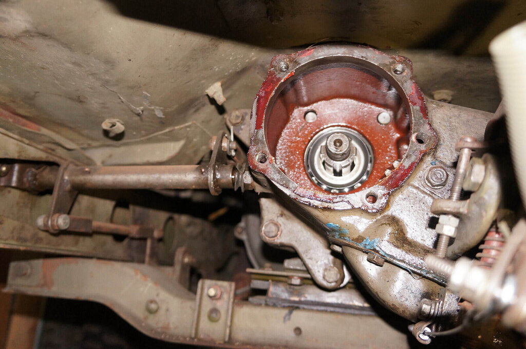
Inside transfer case with drive gear removed. The two shift rails
are visible at the top. Unfortunately, the rails can't slide out here because
of the casting at the back.
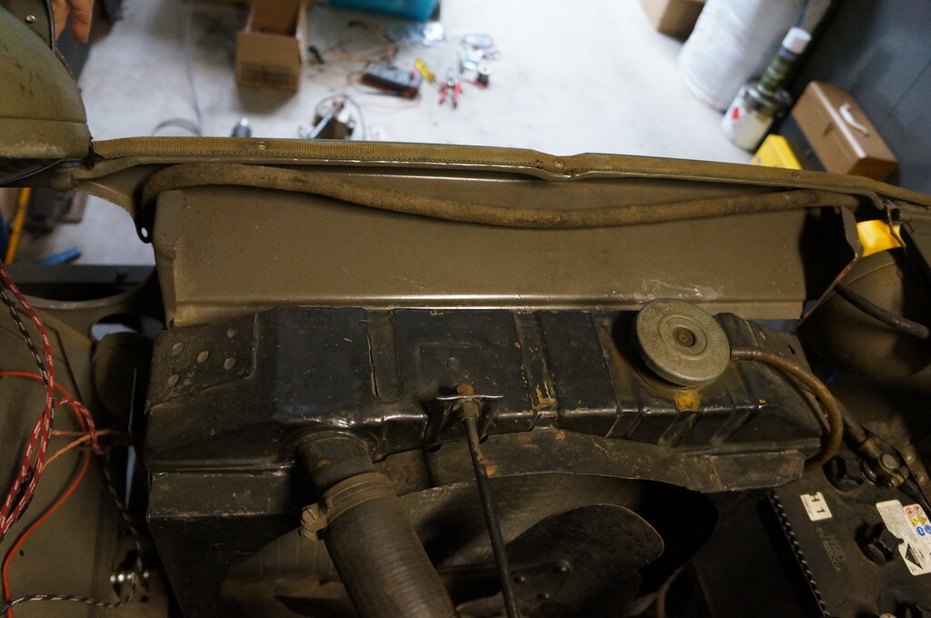
12/1/26: Remove front drive shaft, speedo cable, rubber transfer case mount, clutch release mechanism. Drain transfer case and transmission. Remove rear drive shaft.
13/1/26: Commence removing transfer case after securing mainshaft in transmission.
14/1/26: Replace 1st / reverse shift
rail, ball and spring. Replace ball, spring, and fork screw for 2nd / 3rd
shift rail. Grind interlocking pin channel in transfer case so pin slides
freely.
Reinstall transfer case.
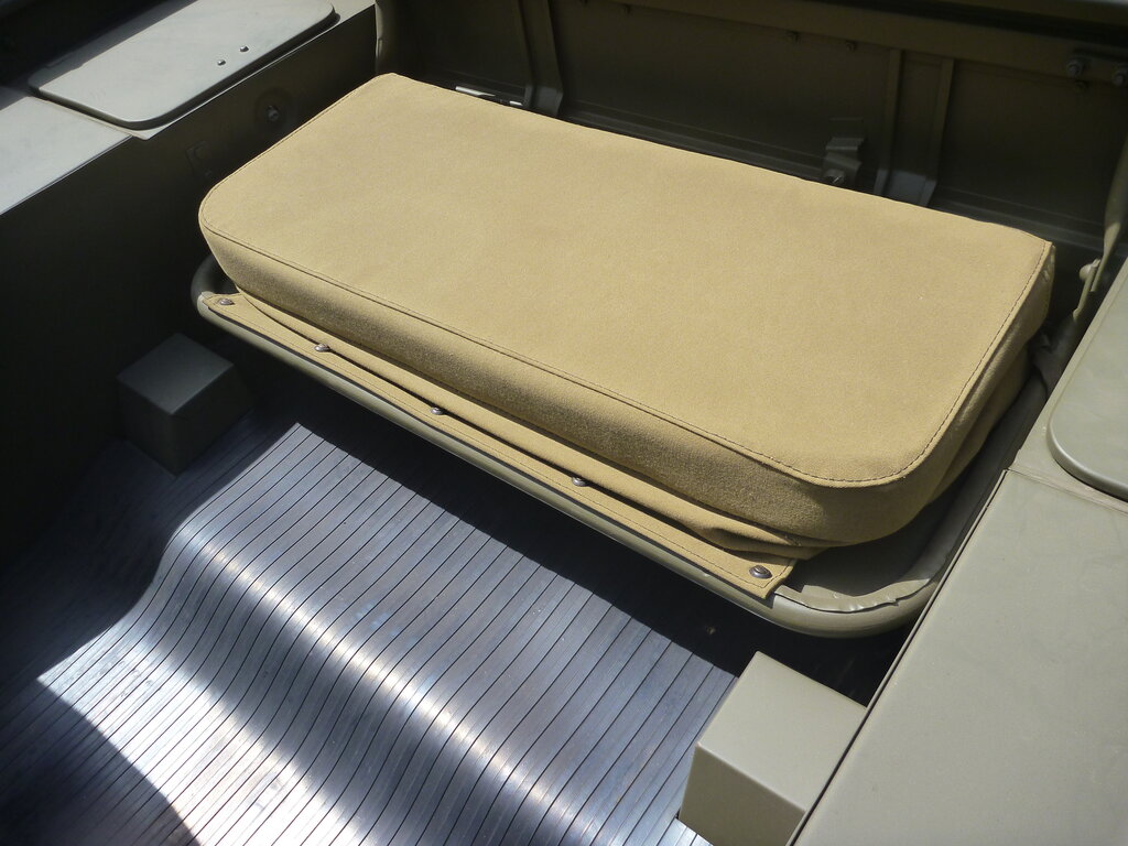
20/1/26: Replace seat cushion screws. Non-originals had been used, and since I had the originals in the box of parts, they were installed. The exception was for the front seat cushions, since holes had been made in the canvas in the wrong locations. I left those screws as they were. They should be nuts and bolts there - all the other ones are self tapping screws. I was told on the G503 forum that my rear seat cushion and frame is not original, due to the location of the screw holes and that the cushion does not extend all the way to back of the seat. On mine the screws face up and are exposed. On others, the canvas flap hides the screws which face inwards.
21/1/26: Made video of the Jeep. The gear shift problem appeared once. This was better than previously, but still obviously not fixed.
24/1/26: Finish clean out of cooling
system and replace with coolant. I used 33% coolant to 66% rainwater.
Attempt to replace the three oil hoses.
The two short ones were successfully replaced, but the long one wasn't.
It turns out this hose has been custom made to fit the oil filter canister
without an adaptor. When I tried to fit the repro hose, it was too large.
Forum discussion revealed an adaptor is required - and I realised that
being a flared hose fitting there would be nothing for the flare to seal
against without it.
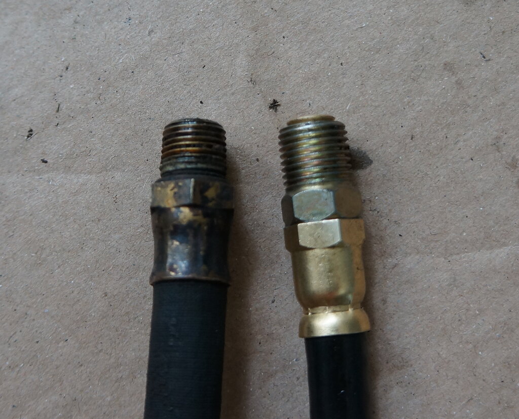
Hose at left is what was already installed. At right is the new
repro.
Old hose shown. There should be an adaptor on the oil filter inlet.
Incidentally, to get at the oil hose connection on the engine block which feeds the filter, it is necessary to remove the fuel pump. It, and the engine mount is otherwise in the way.
26/1/26: Australia Day at Australiana Village, Wilberforce. I displayed the Model T there. There are always Jeeps as well as other vintage vehicles. One Jeep had a rear seat set up just like mine. It was a slat grille MB. So, it appears it is actually correct for early MB's.
Rear seat as fitted to a restored 1941/42 Slat Grille MB.
Another member on the forum showed a photo of his seat and the screws were also facing up. Then I realised a pattern - all three seat frames with upward facing screws were in Australian Jeeps. It makes me wonder if they were locally made for or by the Australian Army.
27/1/26: Made video about the transmission https://youtu.be/Cvs4JF86ACw
30/1/26: First long drive since I've owned the Jeep. It was a 50 mile (80km) round trip. Keeping in mind the need to find the neutral detent when shifting gears, not once was I locked out of 2nd gear. The Jeep went well, and I drove it to, and around, the Blue Mountains town of Blackheath. There is a slight leak with the fuel pump bowl gasket. I'm finding it a lot like the Model T to drive, in terms of thinking and planning ahead. However, the extra power is appreciated! For highway use, it seems happy at 40 to 45 mph.
Jeep at Blackheath.
31/1/26: A longer drive, to the Blue Mountains town of Lithgow. This is a 77 mile (123km) round trip. I'm getting a lot more used to the Jeep and really enjoying driving it. The extra power over the Model T is noticeable and much appreciated! However, one must drive to the conditions and limitations. Those who know the area will be aware of Brown's Gap Rd and Scenic Hill. The Jeep ascended both those with ease in 2nd gear. The odometer is now up to 156 miles; 127 of those since repairing the gearbox.
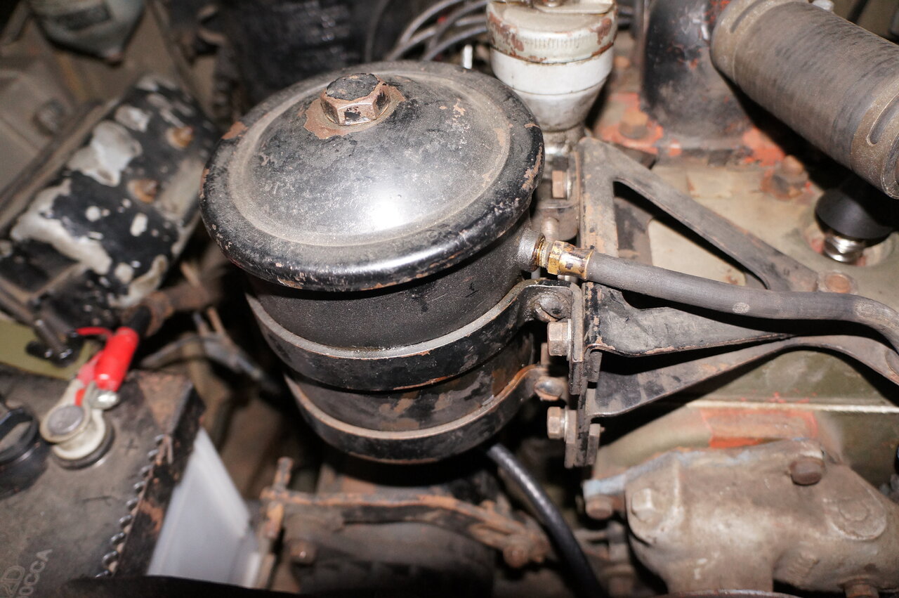
2/2/26: Replaced long oil hose. Noticed oil fill tube has been modified. A bracket has been brazed or welded which secures it to a nearby head stud. The nut is missing. Originally there was a clamp around the tube which secured it under one of the oil filter bolts. Also noticed the original MB engine number is partly visible behind the oil filter. Checked voltage regulator. Battery is charging at around 7.2 - 7.4V.
9/2/26: Found spare wheel carrier missing top left bolt. Bolt found wedged between tyre and back panel. Nut found inside tub. Unfortunately, the wheel carrier had cracked in multiple places.
Decided to replace it since welding would never be as strong, and that there would be metal fatigue near the breaks. The wheel is very heavy! New one is of much better construction, stamped out of one piece rather than being folded and welded.
13/02/26: Installed new spare wheel carrier. Included 5/16" spring washers. Some of the 'original' nuts appear to be Whitworth. They don't fit 1/2" or 9/16" spanners, but 13mm will just fit. I believe some Whitworth sizes are the same as metric.
Grey appearance of the paint appears to be due to sun fading. The
new paint has an obvious contrast. Additionally, the wheel carrier is of
a darker shade than the lock, and what I used for the body repair.
17/02/26: Install horn relay so
that horn cannot operate with ignition off. 1) People like pressing horn
buttons on parked vintage cars, 2) The horn switch design is a bit suspect
in my opinion - I don't want it sounding in the middle of the night. Relay
contacts are in the earth return of the horn as per original. Feed for
relay coil comes from the fuel gauge circuit breaker. I noted a self tapping
Phillips screw for the horn terminal that I reconnected. I don't think
that's original.
Reconditioned a trouble light to keep
in the toolbox. It's an ex Toyota from the 1970's. Needed longer flex (the
plug had been cut off as well), and the bulb replaced with a 6V 18W type.
Also cleaned up the metal cage and sprayed it olive drab.
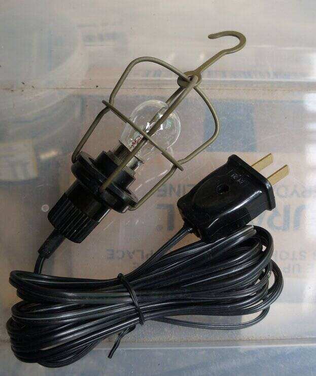
Trouble light, ex. Toyota - at least the Land Cruiser was inspired
by the Jeep.
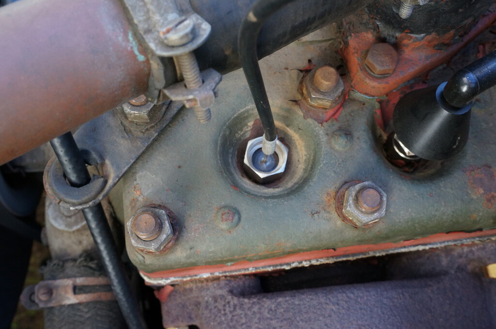
25/02/26: Checked fuel mixture.
I suspect my original adjustment was OK, as far as the Stromberg instructions
go. Nevertheless, I've re-done it accordingly, and in due course will check
the spark plug colour. Also checked the voltage regulator with everything
warmed up. It's 7.26V across the battery with headlights on, which is within
spec. Interestingly, at idle with just the ignition drawing current, the
voltage rises; I saw up to 7.6V.
Also had a quick look at the voltage drop
in the headlight circuit. There is about 890mV drop across the ammeter
with the headlights on (about 20A). I noted the terminals were quite warm.
There was 5.18V at the load side of the ammeter, with 6.07 at the battery
side. By the time the current gets to the headlights, the voltage at the
right side headlight was about 3.85V. This is the furthest distance from
the battery. Of course, with the battery charging, the voltage increases,
but it still isn't correct. Took it for a short drive and it went well.
2/3/26: Investigate voltage drop in headlight circuit. The plan was to measure the voltage drop at each point between the battery and the furthest headlight (which is on the RHS). Since the battery voltage would drop over the testing period, it was felt erroneous to simply measure the voltage between each point and earth. Instead, the actual drop was measured along the system, using the positive battery terminal as the reference. Up to the ammeter was very good, with only 50mV drop up to its input terminal.
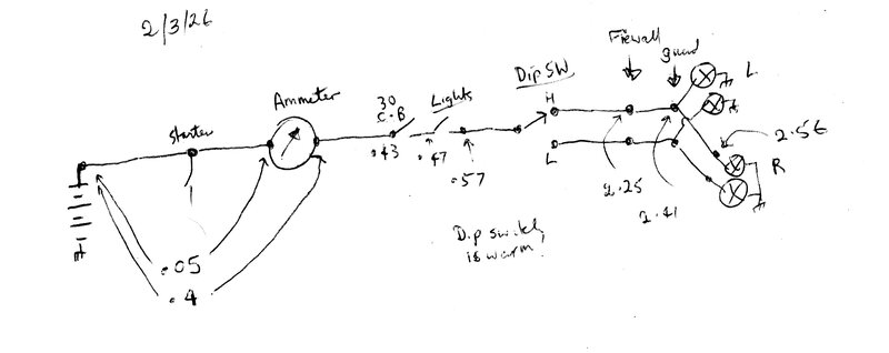
The first significant loss was the ammeter
itself, dropping 350mV. The real problem is the dip switch, losing 1.68V!
Its terminals were warm. The actual drop across the wires themselves is
not too bad, which indicates their gauge is sufficient. It's an interesting
thought to install relays, eliminating the 100mV drop across the headlight
switch, and 1.68V across the dip switch. It would not be difficult to implement
either and really comes down to where to mount the relays behind the dash.
Of course, before seriously considering that, I need to find out why the
dip switch is dropping so much.
Finally worked out where to install the
socket for the trouble light - on the firewall above the LHS footwell using
the holes otherwise used for the oil can. Discovered I actually have all
the elements for the original aerial. All I would need to install it is
the base and mounting bracket. However, it is far longer than necessary
(or practical). I'll have to think about this.
6/3/26: Installed socket for lead light. I made up an aluminium box to take a two pin socket. Mounted it using the screw holes in the firewall used for the oil can holder. (I don't like drilling holes in cars). It was noted that the oil pressure gauge line clamp had been installed using one of these holes (there is no oil can or bracket), so moved it to the correct location - the hole below. Replaced the clamp since the home made one was not that great.
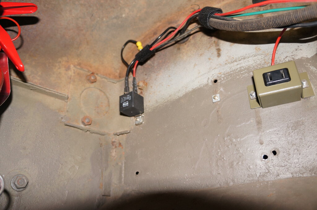
Socket mounted on firewall in LHS footwell. Horn relay at top left.
It's fed from the horn circuit breaker, so always live even with ignition off. I have had to use trouble lights at night in my other cars, so it's something I consider important to keep with tools and other likely parts.
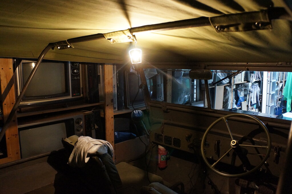
Functions nicely as an interior light too!
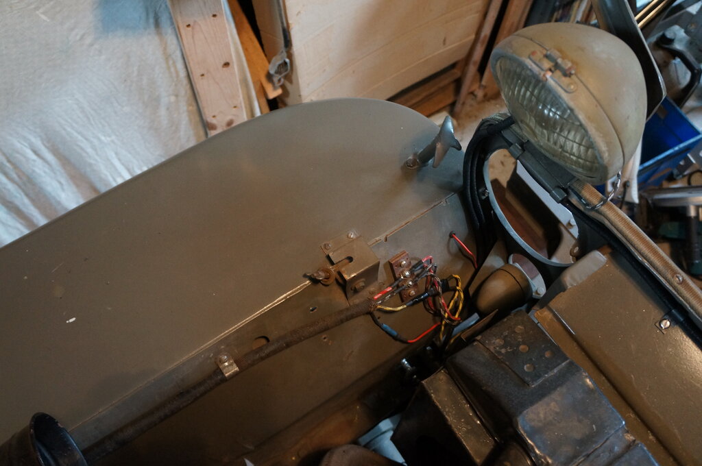
9/3/26: More on the headlight voltage drop problem. Examined the dip switch and found voltage drop between the terminal and brass/copper rivet which goes into the mechanism. This was the source of warmth previously noted. Soldered across the join. Now only about 100mV drop and an improvement in brightness. Previously there was about 250mV across this point. Noticed a join in the low beam wire with spade connectors not far from the switch. It was warm. Noticed a similar join in the high beam wire. Noticed the wire feeding the dip switch from the headlight switch was a gauge too small, and this wire was also slightly warm. At this point I decided to replace all the headlight wiring. The non original bullet connectors for the RHS headlight will be eliminated. Since this wiring is so visible, I decided on vintage style cloth/lacquer wire which I've ordered from www.vinwire.com.au. At $5.50 per metre, and $15.00 postage it's expensive, but comparable to any other suppliers. It's made to order, since you specify the tracer colour and pattern.
13/3/26: Discovered nut missing
which holds the front muffler clamp to a thick piece of canvas, thence
to the body. Another of those "I thought I heard something fall off" moments,
I suspect. The bolt appears to be 5/16", since in the box of parts was
a 5/16" wing nut for the battery clamp, which fitted. Sure enough, in the
table of bolt sizes, that's what it's listed as. So, a 5/16"-18 nut for
my next parts order - it's used on several other things so shouldn't be
a problem. For now, the wing nut will do - but I did add a spring washer.
Checked brake pedal adjustment. There
should be 1/2" free play before the master cylinder piston is enagaged.
Fitted remaining brake line clamps to the rear axle. The repro brake line
required some bending to fit it, and initially I had fitted only one clamp,
as per the G503 video. It had been on my agenda to fit extra clips on the
wheel side of the axle housing. Excess vibration could weaken the steel
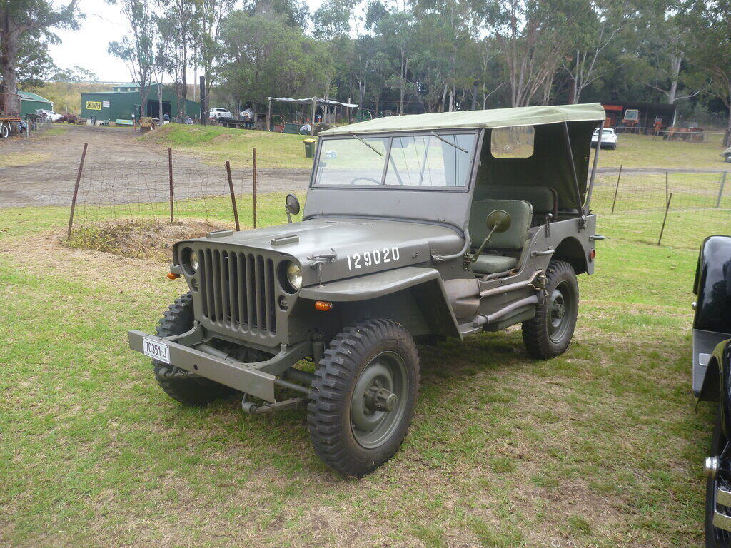
brake line over time. Learned more about the RHD conversion; I now have
a pretty good idea of what it was originally - based on a CJ3B. I talk
about that aspect of it here.
20/3/26: Since I'll be needing the headlights in a couple of weeks, I decided to fix up what was there with what I had - just in case my order wasn't ready, and I hadn't had time to rewire it by then. Eliminated the unnecessary connectors in the dip switch wires. Cleaned up the connections. Replaced wire between headlight switch and dip switch. Now there's 4.85V at the furthest headlight with no charging. Even with a loss of about 1.2V, the brightness is quite good and the filaments are white hot. (26/3/26 - Vinwire order should arrive early next week).
27/03/26: Tested 12V ignition coils for use as an emergency spare. Rather than pay $30 or more for a coil I might not ever need, I examined the possibility of using a standard 12V, and resistor 12V coil, which I already had. Both worked. Video created and uploaded.
30/3/26: Attempted to install flap in spare wheel. Some difficulty separating the rim. Had to jack up Jeep on the tyre to break the bead. Once off, it was clear the flaps would not fit as is.
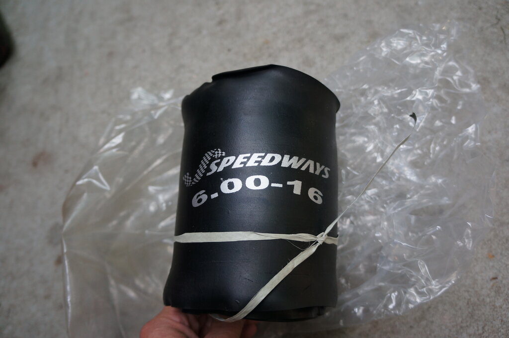
Not for offset valve stem.
Problem is the valve stem hole is centred. It needs to be offset.
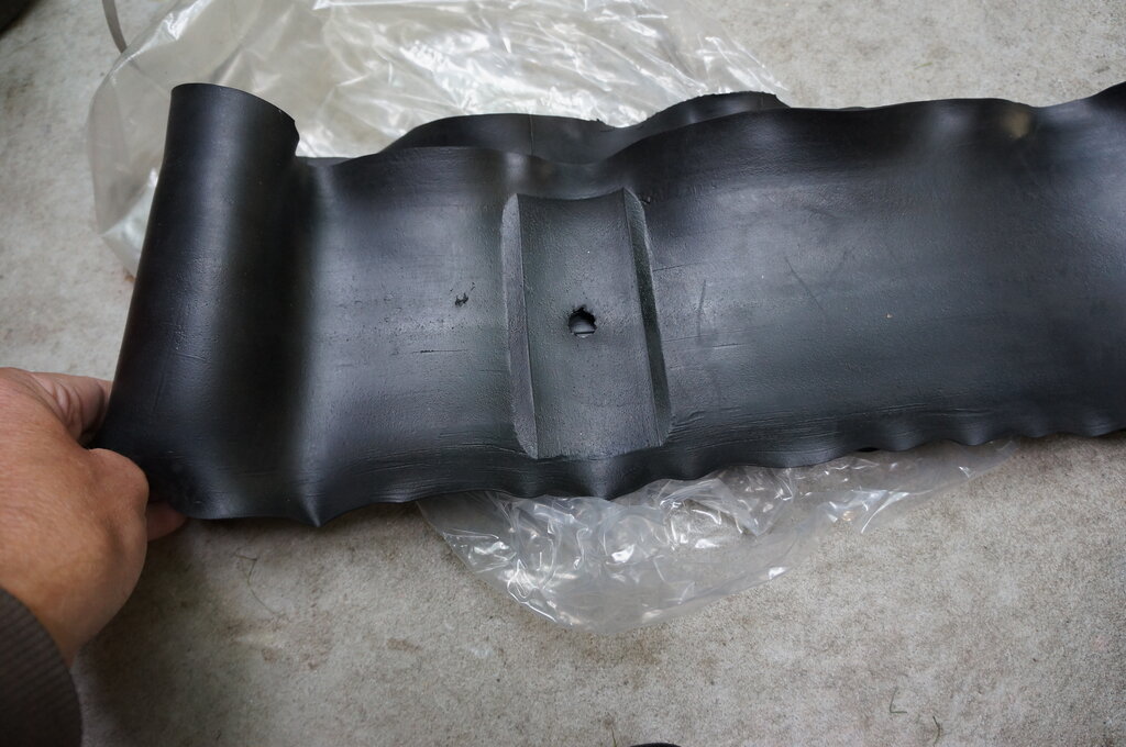
Stem hole would have to be relocated.
I gave up for now. I'm not sure I have
a punch big enough to make a new hole. The intention would be to put the
punched out piece into the original hole to provide support for the inner
tube at that point. Opinion on the forum is that some have run for years
without flaps.
Maybe sometime later I'll have another
look.
31/3/26: Minor job - petrol tank strap kept unhooking. It needed a slight bend. The bolt was then too long so had to pack with washers.
1/4/26: Rewired headlights from the headlights themselves to the terminal block on the guard. Impressed by the quality of the Vinwire. Unfortunately, I didn't get enough to reach the dip switch. In any case, I really need a thicker gauge since that's carrying the current of two headlights.
3/4/26: It appears I have a repro grille. In looking at the headlight wiring there are discrepancies. There is no tab at the LHS of the grille, which takes two clips for both headlight cables.
Should be a tab at the top LHS of the grille to attach a pair of
clips.
No holes for clips across the top.
There should be two holes on the flat part across the top of the grille (top air deflector) to take clips. As can be seen, the loom just rests there. There should also be holes for clips across the bottom of the grille for the black out marker lights.
8/4/26: Fitted anti rattle springs for rear seat. These require 1/4" x 1/2" bolts.
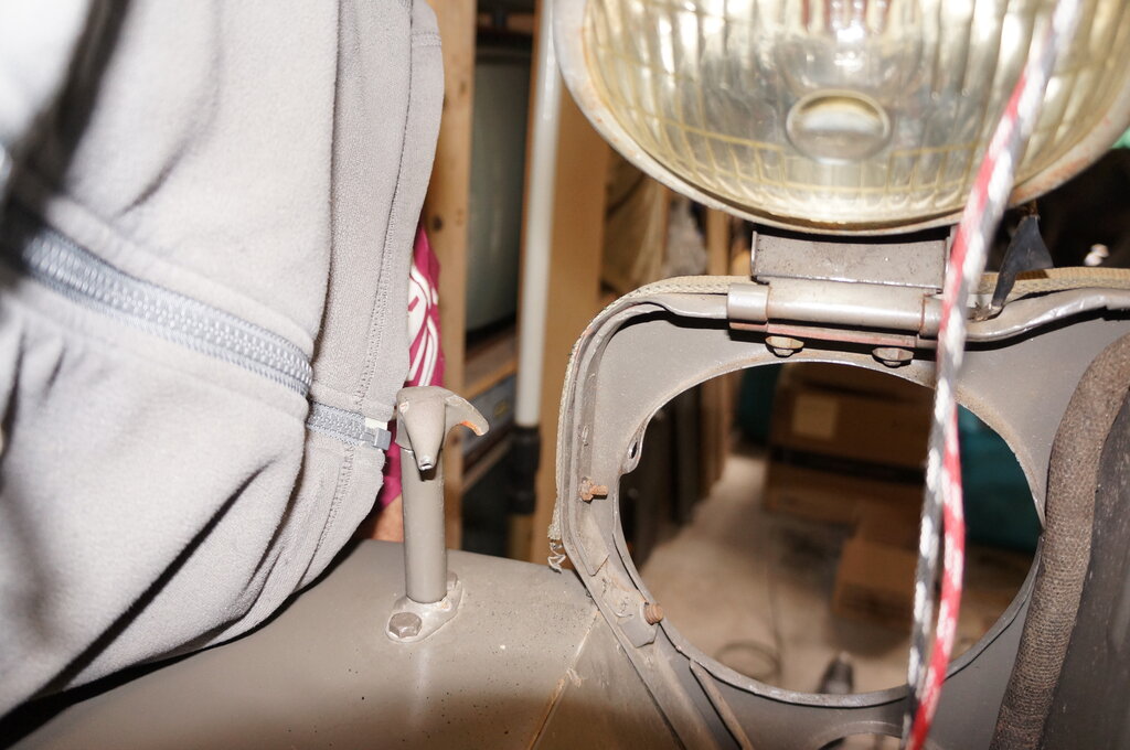
9/4/26: Discovered that the headlight
terminal block is in the wrong position. It should be on the front side
of the headlight bracket; not the rear side. The holes are there, and by
the washer imprints in the paint, they've been used before. So why was
it moved?
Rewired headlights up to the terminal
block. Drilled 5mm holes in the air deflector for the clips. Finding the
location of these required some searching for the factory drawing. This
is available on The Henry Ford site. Search for Ford GPW. Since there is
no tab, I simply drilled a 5mm hole in the side of the grille where it
would be welded, and used one clip to secure both headlight looms.
It turns out the repro wiring loom I bought
for the headlights was too small of a diameter to fit the cloth covered
wires. This took some time and effort, but I got them through. Using a
draw wire soldered to the two headlamp wires, I was able to slowly pull
them through about 10mm at a time. The procedure is like threading wires
through shoe lace. Push down on the tubing so it expands, then pull it
tight further down. It took several hours to do this. Made up new earth
wires for the headlights. Incidentally, a 2m length of loom was just enough
for the headlight wiring across the grille ("Brush Guard Panel" in Ford
parlance). I'm using 4mm wire (14 gauge) for the individual headlights.
I have ordered 5mm (12 gauge) for the wiring between the switch and two
way terminal block.
11/4/26: Trip to the HRSA at Winston
Hills. The Jeep went most excellently. The extra power and speed compared
to the Model T is very noticeable (and appreciated!). Alas, a fault developed
with the speedo. The reading started fluctuating madly, and was going off
scale. Perhaps the fault was there before, but I hadn't driven at this
kind of speed before (I'm guessing 80km/h or more). I could hear a noise
which sounded like it was from the speedo cable. On the return trip, closer
to home, and going at a lower speed, the fault seemed to fix itself.
My suspicion is the speedo cable, and
I have a new one to try.
Incidentally, while getting the Jeep ready
yesterday, I noticed the front generator mount bushing seems to have failed
- I always thought it odd that the generator was at a slight angle. So,
that's another job, and while at it will re-instate the spring actuated
latch on the generator brace.
13/4/26: Attempt to replace speedo cable. Alas, the nut which secures the cable to the transfer case is too small or has the wrong thread pitch. It starts to bind after a few turns, and before the cable is fully seated. Not impressed. The previous one goes on all the way finger tight. Not only that, I'm not impressed by the amount of drag in the cable - like it's full of dried grease. It's a "Seal Tested" brand.
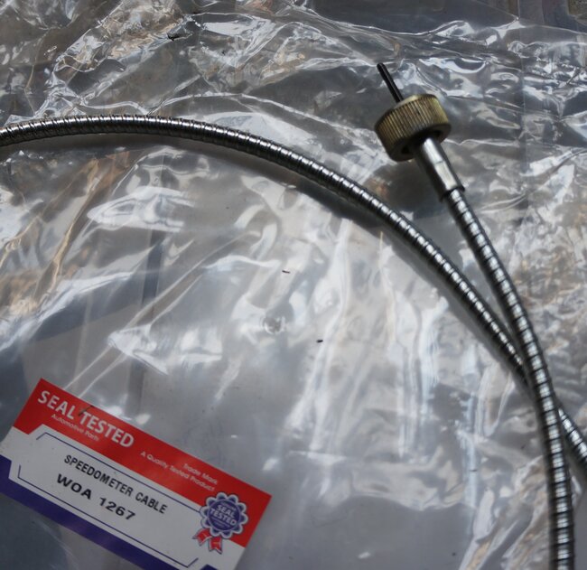
Threaded cap won't go on all the way.
14/4/26: Tested original speedo cable with a drill. It worked perfectly. Possibly a lack of lubrication of the cable was the problem. I had seen reference to this in one of Paul Shinn's Model A videos. Also, the cable came around at a rather sharp angle into the transfer case and this could also be a problem. I lubricated the cable with Penrite wheel bearing grease, and re-installed it, re-routing it through the chassis frame, which is apparently how it is meant to be. Also made a clip to secure it to the firewall. Tested with the Jeep on jacks, it certainly worked up to 30 mph. I dared not go any faster, lest it fell off a jack and launched itself into the Model T parked in front of it. I'll find out next time I take it driving.
Original is longer than the repro.
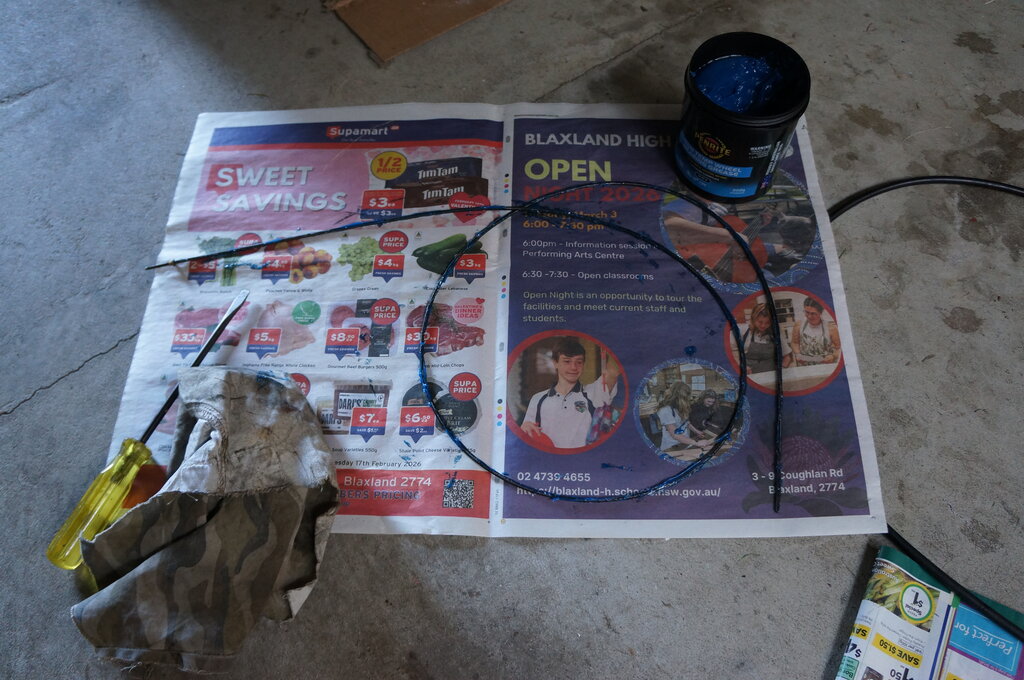
Lubricating inner cable.
16/4/26: Rewired blackout marker lights. It's necessary to dismantle the lights to rewire them, since there's almost no room behind the sockets to feed the wire through. Both my B.O. markers are different, although they look the same from the outside. One, at least, looks like a repro. Drilled bottom of grille for the three clips. Originally, there was meant to be a 3 way bullet-type connector to connect the lights into the feed. I used modern bullet connectors and made my own 3 way connector. Repro 3 way connectors are available, but expensive, and I've not seen the male connectors available.
18/4/26: More on headlights. Completed new harness between the 6 way and 2 way terminal blocks.
Two way block relocated to correct position.
20/4/26: Finished headlight wiring - 6 way block to dip switch and thence to light switch. Wiring much tidier behind the dash now. Secured with clip. Headlights work well!
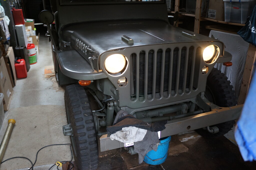
Proper brightness now.
Discovered horn is not original. It's a Delco-Remy K26. Since I had the vibration mount in the box of parts, I decided to mount the horn using it. I have not seen an official explanation for why this is needed, but the main opinion is that it reduces vibration from the horn going into the body of the Jeep, when the horn is used. I presume this means more of the input energy emanates from the throat of the horn. In any case, it's probably the loudest horn I've ever heard. To adapt the horn required moving one of the 1/4" bolts to line up with the vibration mount. These bolts were not original. The vibration mount on the horn side required drilling out to 1/4".
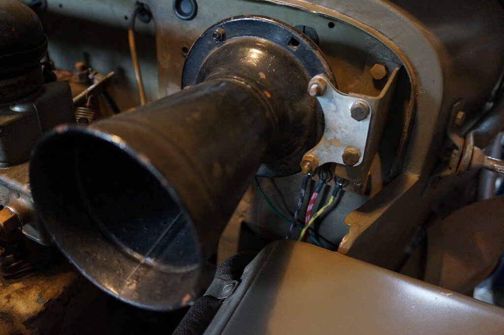
Horn now mounted with vibration mount. Note new headlight and B.O.
marker light wiring at the terminal block behind it.
30/4/26: Commenced making new flasher/hazard light module.
2/5/26: Learned about the ignition switch - it's for a Deutz tractor. Traced out connections.
4/5/26: Finished installation. Everything works as it should. Installed B.O. Drive light switch in hole to the right of the ignition switch. The dash looks so much better now. Electrical system finished!
16/5/26: Installed hood bow wave washers.
17/5/26: Trip to Cambelltown Steam Museum. Noticed headlight beams were swapped on one headlight. No wonder the difference between high and low beams had always been indefinite! Fortunately, I didn't actually need the headlights for the trip.
Whilst at the museum, the Jeep was approached
by two members of a club that always displays military vehicles there.
One of them has a particular disliking for RHD Jeeps - I've spoken to him
before. He was of the opinion that my Jeep 'should not be on club plates
because it's modified'. I explained that it was a requirement of the Victorian
state government at the time. He said 'We're not in Victoria'. By that
time they both wandered off. Interestingly, neither of them was actually
interested in the Jeep itself. No questions were asked about it, and they
didn't even look over it. I guess because it wasn't part of their
club, it might as well be non-existant. My gut feeling was right when I
was invited to join that club last October...
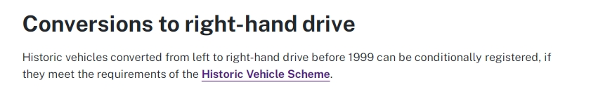
Anyway, here's the relevant NSW legislation
about older RHD conversions, from the RMS website:
A father let his offspring explore the
Jeep without my permission, and sure enough, it was only moments before
one of them started pressing the horn button. Good thing I'd wired it through
the ignition switch. I'll remember to put the door straps across next time.
Other than that, the Jeep went very well,
and it was a great day out. The speedo problem is still there, but much
less so, since I lubricated and rerouted the speedo cable.
18/5/26: Examined the headlight connections. It turned out that the 3 pin base connections on the bulbs might not be standard. The two bulbs were not the same brand. One was K.D.K. (the same as the rear lights), and the other did not have a brand. The non-branded bulb had the same connections as labelled on the socket, and the beam operation was correct. The K.D.K. beam connections were reversed. I could have changed the contacts around in the socket, but figured I'd have to reverse them again if I ever replaced the bulb. And it's a bit more involved to do that. I simply reversed the connections at the two way terminal block instead.
28/5/26: Installed Footman loops
under front seat where roof canvas is stored. I used 10 gauge x 18mm countersunk
self tappers.
29/5/26: Installed rear seat retaining
brackets. These use 1/4" x 1/2" bolts like the retaining springs. Replaced
petrol tank strap bolt with one of a more suitable length; 5/16" x 40mm.
Installed roof canvas stowage straps under front seat.
8/6/26: Went for a short test drive and noted a metallic rattling noise starting to appear. It was the fan hitting the generator pulley. The generator mounting bushings have become a lot worse. I've got a new set ready, which will be the next job. Since the weather has cooled somewhat since my last trip out (the steam museum), I've noticed the gear shifting is more difficult between the two shift rails. It's the same problem which I've explained before, and I assume the higher viscosity of the gear oil, when cold, is making it more difficult to find the neutral detent.
13/6/26: Dealing with the generator mounting. Discovered the nut on the front mounting bolt was missing. Replaced the rubber bushings - prick of a job. Got them in eventually. Discovered the mounting bolt kit from JMP does not include the flat washers which go on the threaded part of the bolt. I resused one of the old ones, and replaced the other since it was missing. Having got that all together, next thing was the brace and so called "T handle". One of the things I wanted to do was re-enable this, since the spring was missing, and the T handle was clamped to the generator instead of being held by the spring. The brace had been installed the wrong way around too. Anyway, with that sorted, the next problem is the fuel line clamp which shares the brace pivot bolt on the timing cover. The line will need to be bent for it to fit where the clamp should go. There was a foreign clamp hanging on the fuel line, not secured to anything. Not good to have the weight of the line on the fuel pump connection.
14/6/26: Finished the generator mount installation. It was necessary to bend the fuel line slightly because it didn't line up with the line coming from the fuel filter. This in itself had been bent to accomodate the RHD conversion.
Fuel line clip in correct location.
Brace mounted correctly, and spring replaced. Generator now in correct
alignment for the first time since I've owned the Jeep.
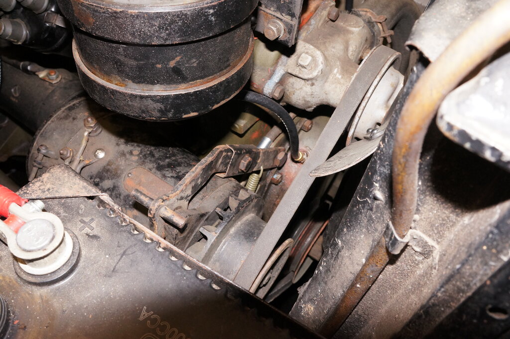
The generator brace is adjusted so there is 1" of deflection in the fan belt between the water pump and generator pulleys. The generator is incredibly heavy for its size. I'm guessing something towards 20kg.
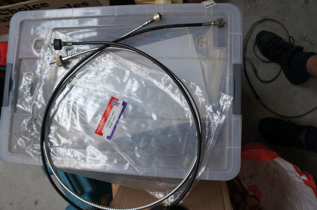
8/7/26: Installed new speedo cable. I purchased another speedo cable and it had the same thread binding problem. It turned out the thread on the speedo drive sleeve on the transfer case was damaged, hence the cause of the binding previously noticed. Obviously, the previous plastic coated speedo cable had a coarser thread for the cap which screws to the transfer case. A jeweller's file was used to tidy up the thread, and then the repro screwed on easily with only finger pressure.
Speedo cable at left. Thicker steel cable is for the hand brake.
I had to re-route the cable slightly, since it is shorter than the previous one, and was in the way of the clutch pedal.
Horn connection blanking plate.
Also made up a blanking plate to cover where the horn wire brush would normally be. It would be all to easy for a small object to fall in, or dirt to get in and wear the ball bearings for the steering box.
12/7/26: Rear brake line is not secured anywhere between the master cylinder, and the hose connection at the rear chassis cross member. Started to mount clips to secure to chassis rail. In the first instance, there was already a suitable hole in the chassis rail for a screw, but even with my good dexterity, was too difficult to get a nut behind it. So, I used a 4mm Rivnut which fitted perfectly. Another one needs to be mounted further to the front - yet to be done. This all of course is because of the RHD conversion; with no provision for securing brake lines on the RHS.
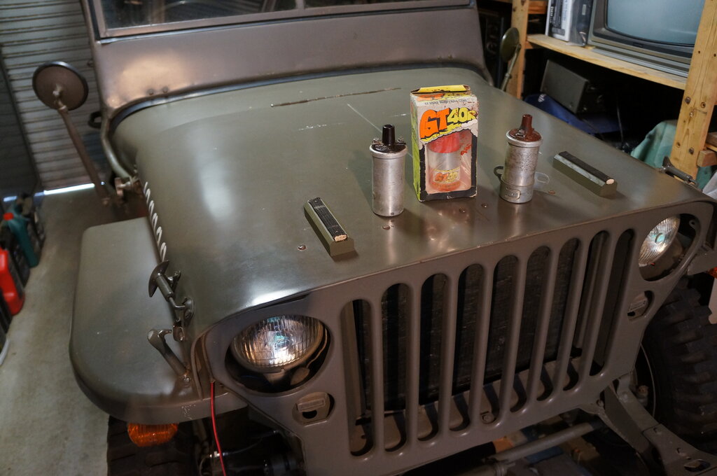
15/7/26: Tried out the "Colortune" transparent spark plug.
Colortune spark plug is transparent. Flame should be just on the
change from orange to blue.
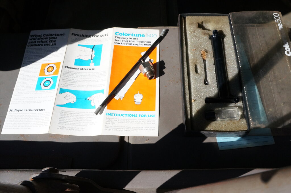
Amazing to think I completely forgot I had this, but so useful is
it.
This tool is used to set mixture by the
colour of the combustion flame. In particular, I wanted to check the idle
mixture as I suspected it might be slightly lean. It was OK, but found
better performance with a 1/4 turn richer.
I also tested a Hawk 620 exhaust gas analyser.
This too indicated things were OK. I'll do a separate article on
this instrument, once I've traced out the circuit. It's quite interesting
how it works with such a simple circuit. And finally, tested my two commercially
made Hawk timing lights. One is a Xenon type, and as such contains an inverter
to drive the Xenon tube. Conveniently, it works from 6 or 12V. The other
type is just a neon tube in series with the spark plug. It too worked satisfactorily,
and the timing mark on the flywheel was close to where it should be. Yet
to be tested is a Hawk tacho and dwell meter. Incidentally, all these test
instruments were given to me some years ago at the HRSA, and I'd actually
forgotten what I had, it was so long ago. And since they weren't something
I needed with the Model T or Hilux, they remained unused. Well, now I've
got just the right vehicle for them all. A classic case of "I might need
that one day"...and I did!