Good thing I didn't drive it home!
24/8/25: Replace plugs to get started. Fit hip pads adjacent to front seats.
25/8/25: Adjust voltage regulator
for 7.2V at battery. Was 6.6V. Headlights very dim unless charging. About
1.56V measured. Indicators did not work unless engine running.
Replace windscreen to cowl seal.
Notice front right brake hose leaking.
Good thing I didn't drive it home!
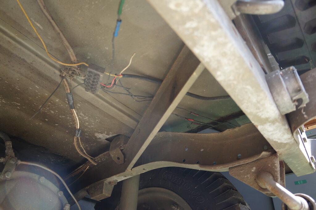
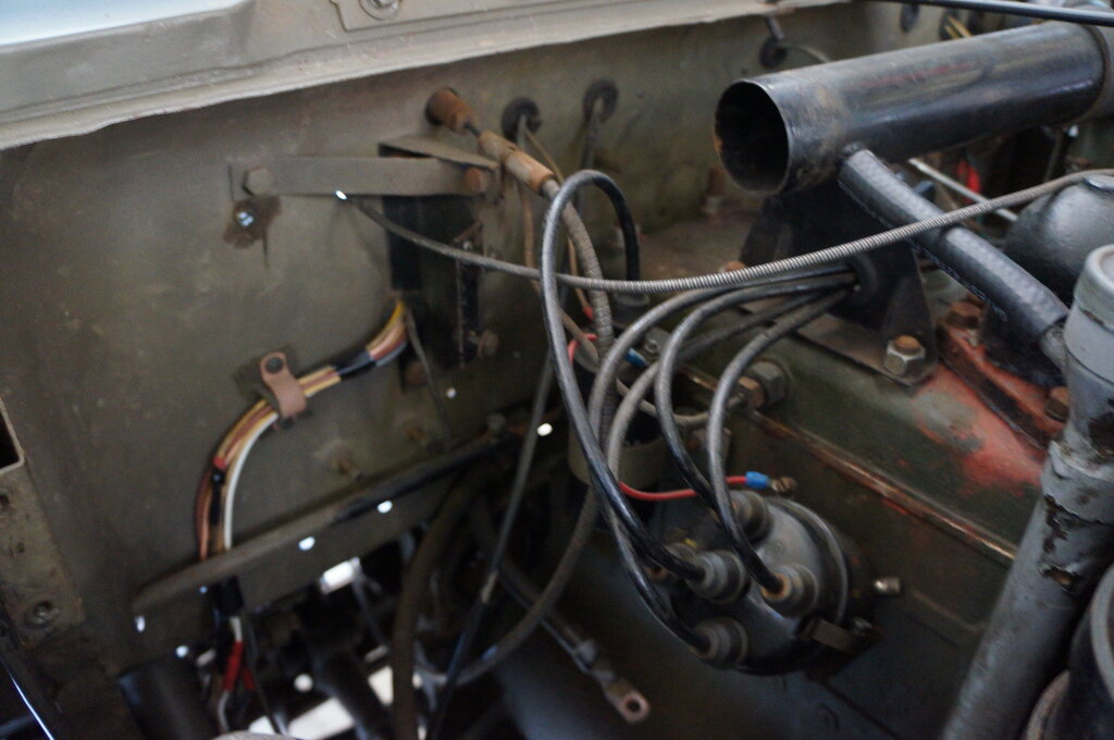
27/8/25: Examine wiring - mistakes
noted. Voltage regulator fed into the system via 20A horn circuit breaker.
High resistance between battery and ammeter responsible for dim headlights
and inoperative indicators.
Brake light not through ammeter. No circuit breaker for light circuit.
Wiring gauge too small for 6V in some instances.
Rewired ammeter.
28/8/25: Reconnected 5A circuit breaker for fuel gauge, and 20A circuit breaker for horn. Better access to C.B.'s if speedo removed. Need to check regulator adjustment again in view of incorrect wiring found.
30/8/25: Made bracket to attach
30A C.B. to light switch.
Terminal broke off brake switch - previous repair with solder.
Started on indicators - fitted 6V lamp into switch. There was an unconnected
12V bulb there.
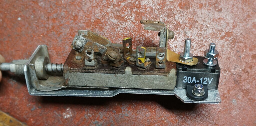
Original circuit breaker is no longer available, so adapted modern
generic type.
1/9/25: Brake / park light filaments
on RHS found to be reversed.
Indicator bulbs on rear too low wattage (3W) for flasher to work correctly.
No output from pilot light (P) terminal on flasher because of this. Replaced
with 21W.
Brake lights need rewiring.
Bodgie trailer socket connection in wiring noted.
Reinstalled indicator switch.
2/9/25: Made new wiring harness
for rear lights.
Found number plate light bulbs to be 12V. No wonder they were dim.
Short circuit found in LHS brake light socket.
Decided a rewire was in order when I saw this.
3/9/25: Finished rear light wiring
and ran new wire to LHS indicators.
Made buzzer circuit for indicators.
Reconnect horn - crimp connector came off wire.
Mixture of old and new wiring.
6/9/25: Replace brake switch and
install new connectors for it - strange type of bullet connector?
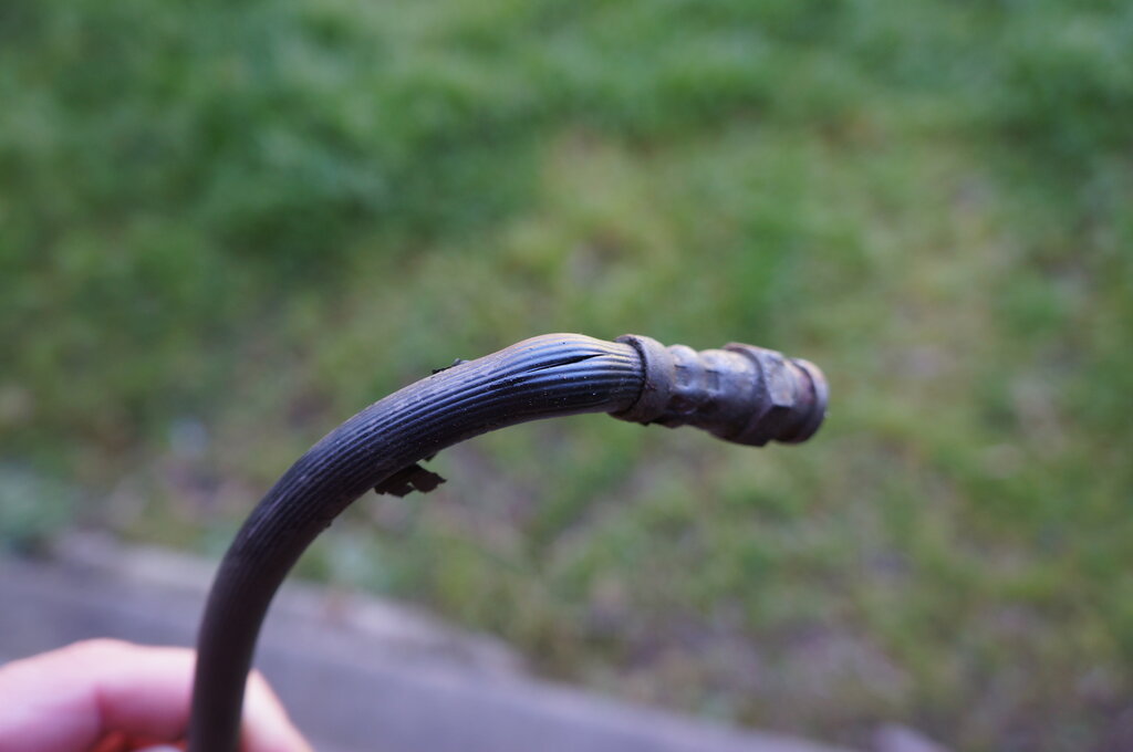
Fix choke cable - crushed under carburettor clamp.
Replace battery clamp bolts.
High and low beam headlight connections need to be reversed. High beam
indicator is on with low beam.
Installed 10A blade fuse for indicators.
8/9/25: Reverse headlight beams.
Degrease starter Bendix - engagement not always as it should be. This needs
further examination. There is a possibility the Bendix has the wrong number
of teeth.
Readjust voltage regulator to 7.2V now that it's connected correctly.
Check steering box mount to see if angle of column can be raised. It's
already at its limit.
Install surround ring for dip switch.
Install new air hose and clips.
Handbrake cable observed to be sticking.
Starter motor out to examine Bendix.
9/9/25: First order of parts from
Milspares.
Dismantled front brake hoses. RHS blocked as well as leaking. LHS hose
same as Hilux.
11" hose in box of parts too short for RHS. S shaped solid brake line also
too short for RHS.
11/9/25: Get new brake hoses made
by Pirtek.
Milspares parts arrived.
Attempt to connect brake hoses. Need thinner retaining clips. Used new
S shaped brake line on LHS.
LHS front wheel bearing needs replacing.
Ordered clips for brake hoses from eBay.
12/9/25: Replace steering wheel
with 15" version. Splines tight.
Replace handbrake cable. Not sure about clips on end.
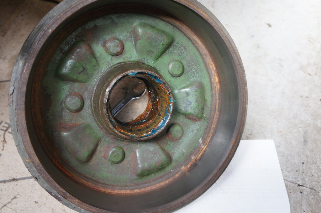
Remove RHS freewheeling hub in preparation for hub/drum removal. This was
necessary to access the wheel cylinder which was likely full of sludge,
given the condition of the associated brake hose. (All wheel cylinders
had been replaced by previous owner).
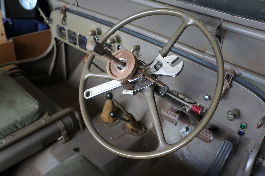
Removing orignal steering wheel. This is the 17" Sheller type.
New 15" steering wheel in Willys style. Much more comfortable for
tall people.
13/9/25: Remove RHS front hub to
access wheel cylinder.
Remove hex freewheeling hub screws, then nut on axle.
Remove six 9/16" bolts on FW hub - really need thin wall socket.
Remove big nut after bending washer.
Remove next nut and pull off hub.
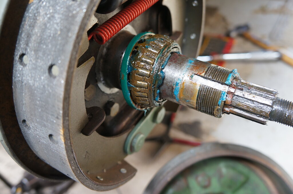
Remove brake shoe cams then shoes.
Remove wheel cylinder - some sludge inside and starting to pit.
Clean up and reassemble.
Note sure about axle end play - it's 3mm.
Cover off freewheeling hub.
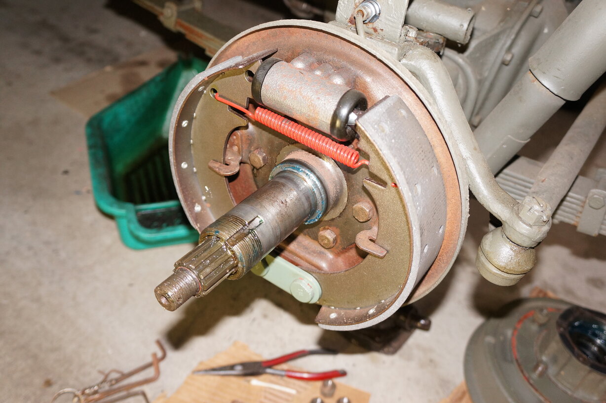
Access to wheel cylinder.
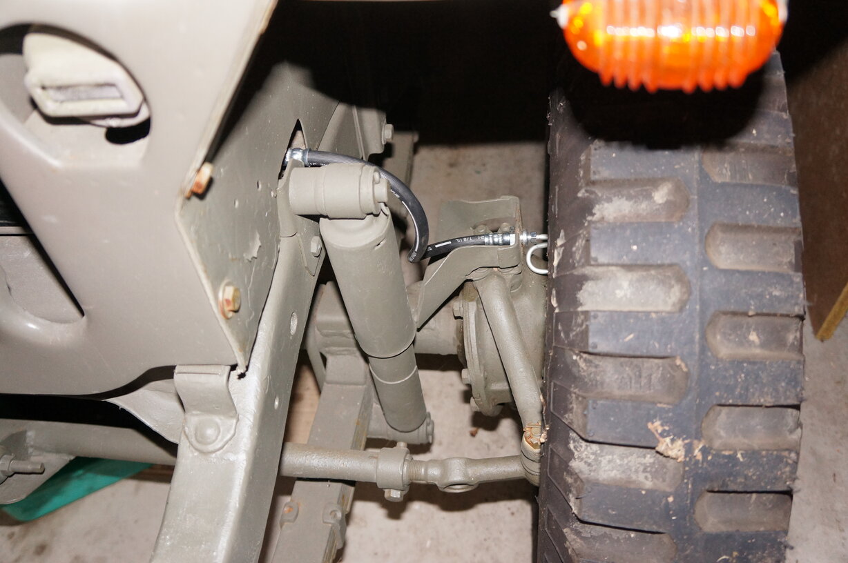
Front LHS brake hose replaced.
Front RHS brake hose replaced.
15/9/25: Removed rear brake lines.
Attempted to install new brake lines but different bracket for T junction
on diff has been fitted in different location.
Ordered correct bracket and two hub washers for future front wheel work.
18/9/25: Installed new T piece bracket.
Installed brake lines after much bending.
Installed hose retaining clips.
Replace generator earth screw - it was a random self tapper and should
be a proper screw.
New rear brake lines.
20/9/25: Bleed brakes. Front LHS
hose, rear T piece, rear flex hose all leaking and needed more tightening.
Note that new bracket for T junction inhibits access for flare nut spanner.
Will need to cut away part if this becomes a problem.
Not keen on access to fill master cylinder. Used syringe and short tube.
Reinstalled battery. Horn sounded. Short circuit somewhere.
Test fit all three vehicles in garage. They all fit!
22/9/25: Replace horn wire in steering
column. Switch erratic but improved it. Horn relay via ignition might be
good.
Adjust handbrake - seems to work OK.
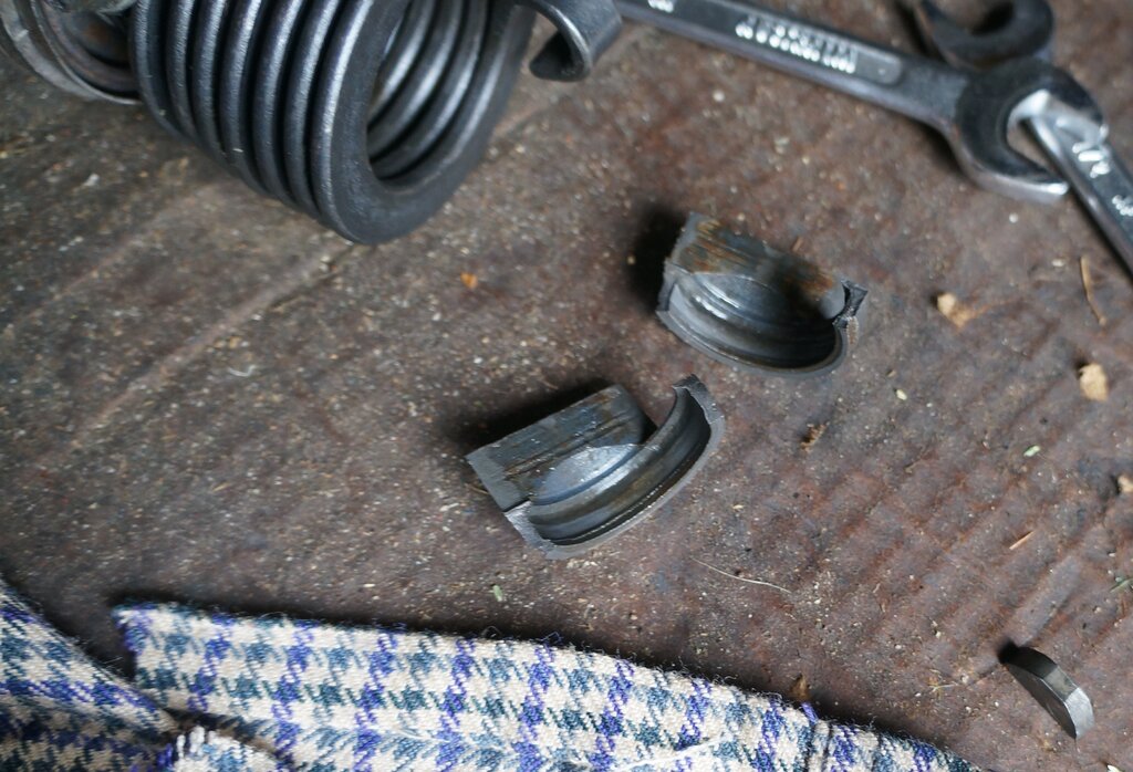
Examined shock bushings. Seems to be generic type same as Hilux.
23/9/25: Get shock bushings from
Repco. Install on front shocks - definitely same as Hilux.
Discover rear shock bushings are different and unable to find replacements.
Australian made Monroe shocks had been fitted a long time ago.
24/9/25: Order new rear shocks -
the bushings for the official ones are readily available (and come with
the new ones).
Replace steering box gasket.
Replace transfer case mount.
25/9/25: Refill steering box - used
syringe.
Tried to adjust play out of steering box, but binding beyond centre. Had
to back off, but has play. Suggestive of the worm gear or steering sector
shaft pins being worn. Will have to examine.
Replaced rear shocks. Compressing the bushings to get the split pins in
was very difficult and had to use all sorts of bodgie methods.
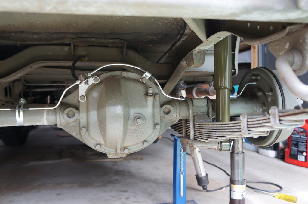
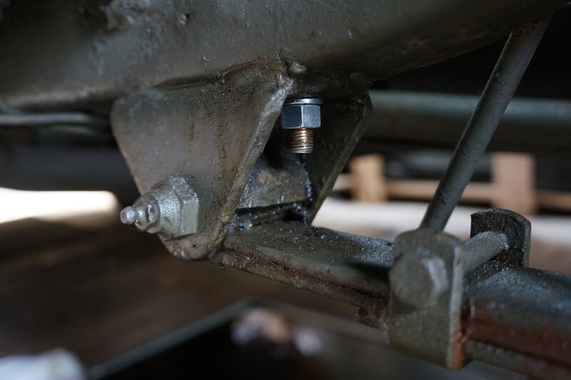
27/9/25: Disconnected rear RHS leaf spring from chassis bracket. Attempted to weld the bracket. Total disaster. This bracket being bolted only, and not welded, was one of the things it failed on with the previous owner's registration attempt.
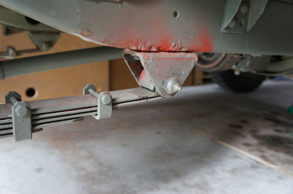
The spring mount before my welding attempt. It is supposed to be
welded as well as bolted. I found the limit of my skills with this one!
29/9/25: 2nd attempt at welding
- this time with DC welder. Yes, the arc was easier to strike and maintain,
but the result was still a total disaster. Ground off the embarrassment
before anyone might see it.
This is my first stumbling block and not sure what to do.
30/9/25: Got spring back in since
I had given up with welding it, and the Jeep needed to be mobile.
And here's a handy hint: Disconnecting
and reconnecting the leaf spring is a right pain in the arse. It is not
like the book says. Problem is the spring curves inwards when under no
load. Needless to say, the eyes no longer line up.
After spending half a day trying to get
the spring back in, I took a different approach. By disconnecting the axle
from the spring, the spring is only tethered on the other eye on the U
shackle at the rear. The spring is free to move forward so the chassis
eye lines up.
Then, it's a simple matter of jacking
up the spring so that it meets up with the axle mount, and reinstalling
the two U-clamps. The Jeep must be supported by stands under the chassis
rail, and also another jack under the diff whilst doing this work. Once
I did it this way, it was very straightforward and everything went into
position.
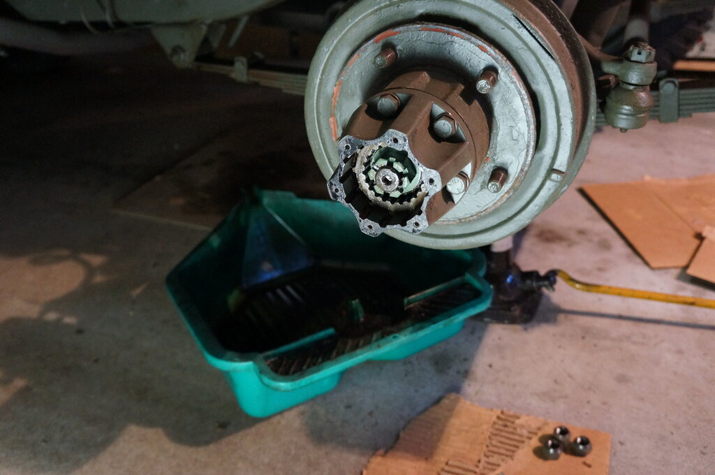
5/10/25. LHS front wheel bearing
replacement. I had previously noted a rumbling sound and feeling of roughness
in the LHS front wheel. Such symptoms point to the wheel bearing.
First thing to do is to remove the freewheeling
hub.
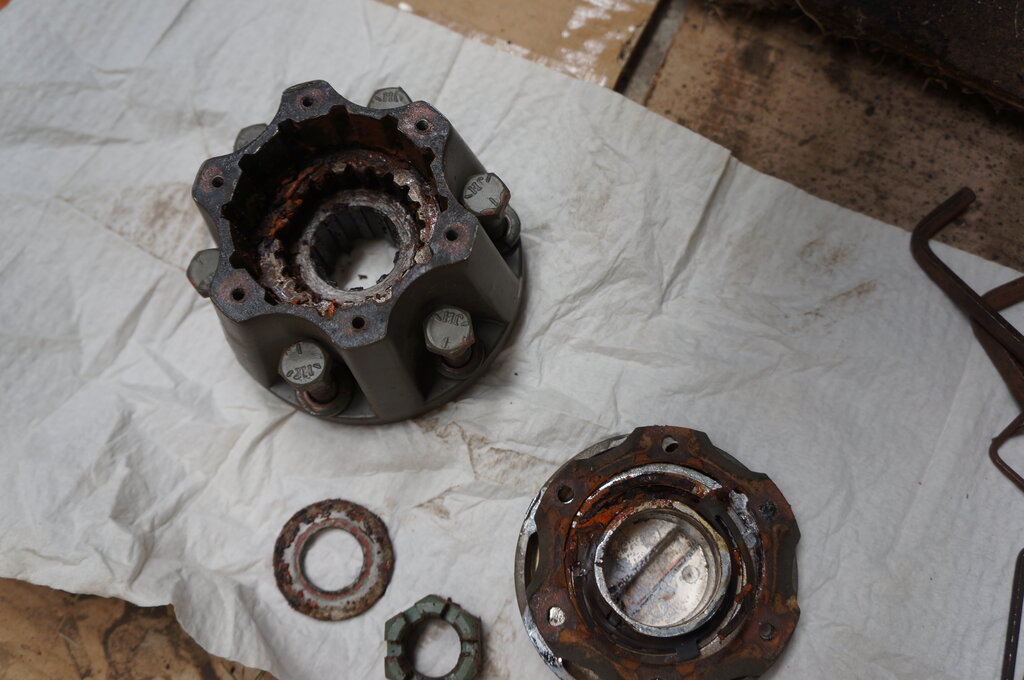
Rust in freeewheeling hub.
There was a lot of light rust inside. Also, when I removed the front wheel, surface rust was present where it mounts on the hub. I had noted photos from the previous owner showing it stored in a carport. The LH side of the Jeep faced the open side of the carport.
Jeep had been stored exposed to the weather.
Freewheel hub removed and still more rust.
Rusty water had penetrated into the hub.
Bearing rusting and pitting.
No wonder there was a rumbling sound. The
bearings were quite pitted on the rollers. It was not difficult to replace
them, although it was an all day job. Conveniently, new bearings and seals
had been supplied.
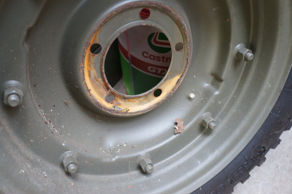
Note that for the LHS of the Jeep, the
wheel nuts are removed in a clockwise direction.
When replacing the bearings, tighten the
first nut to 50 ft. lbs, then back off 1/6 turn (i.e. one flat of the spanner).
This is supposed to apply the correct preload. It certainly felt like it
did - and it rotated smoothly.
The next nut (after the bendable washer)
is also done up to 50 ft. lbs.
There was about the same amount of axle
end play on this side as the other.
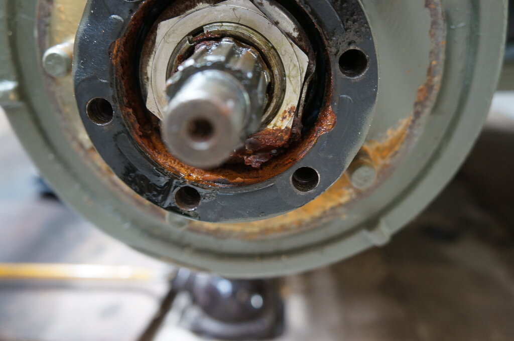
The freewheeling hub had to be dismantled and rust cleaned out. It was noted the spring clip for retaining the sliding part of the hub had rusted and will probably break apart at some point. It is not super critical.
The Selectro freewheeling hub instructions
imply tightening the axle nut to 10-15 ft. lbs. On the RHS this was impossible
if the nut castellation was to line up with the split pin hole. In that
instance, it had to be done up to around 50 ft. lbs. However, for the LHS,
the slot lined up with less than 20 ft. lbs. (the lowest my torque wrench
reads).
An interesting thing observed was the
brake light came on while doing this work. I can only put it down to pressure
on the wheel cylinder while removing the drum actuated the switch (it's
a hydraulic switch). Once the drum was back on, stepping on the brake pedal
fixed it.
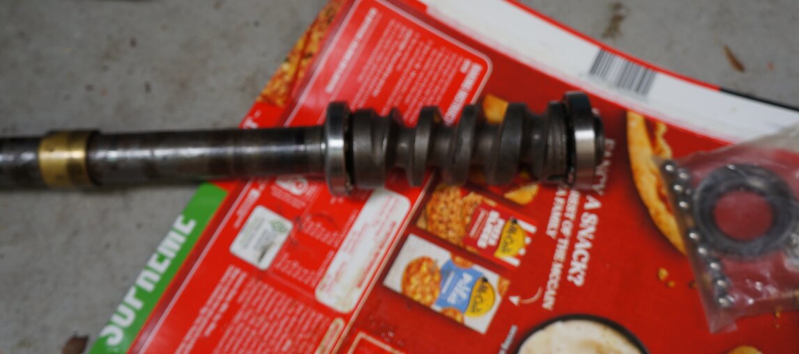
7/10/25: Time to deal with the steering play! First thing was to get the steering sector shaft out to examine the pins for wear. This entailed opening the steering box, ruining the gasket I'd just replaced, and getting all the lubricant out. Getting the pitman arm off was not easy at first. I attempted to remove the whole steering column with box, but couldn't get it out with too many things in the way. It turned out that removing the entire fender was the solution. It's easy to remove and service access is then excellent.
Removing fender gives good service access.
However, back to the pitman arm removal
- my cheap puller is just that. The problem is the arms spread apart under
tension, then they slide down the side at an angle, gouging into the metal.
Of course, it doesn't come off.
A YouTube video showed one of these pullers
with a piece of angle steel welded across it so the arms can't spread.
Since I didn't have such a piece of angle, and as I've learned, my welding
skill is pathetic, I tried a similar method using a G clamp.
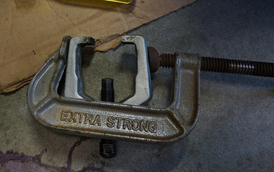
G clamp stops arms spreading under tension.
With the pitman arm removed, and the steering
shaft sector out, it seemed the pins were in very good condition. I know
the previous owner had work done on the steering box. He mentioned sending
it to someone, and it seemed that the bushings and seal were replaced.
That leaves the steering shaft/worm drive.
And here I found something rather disconcerting. I wanted to measure the
steering shaft length because of my suspicion it might be from a CJ. If
it had to be replaced, I'd need to check I got the right length replacement.
The original MB/GPW should be 40.5", but I understand the later CJ's used
41.5".
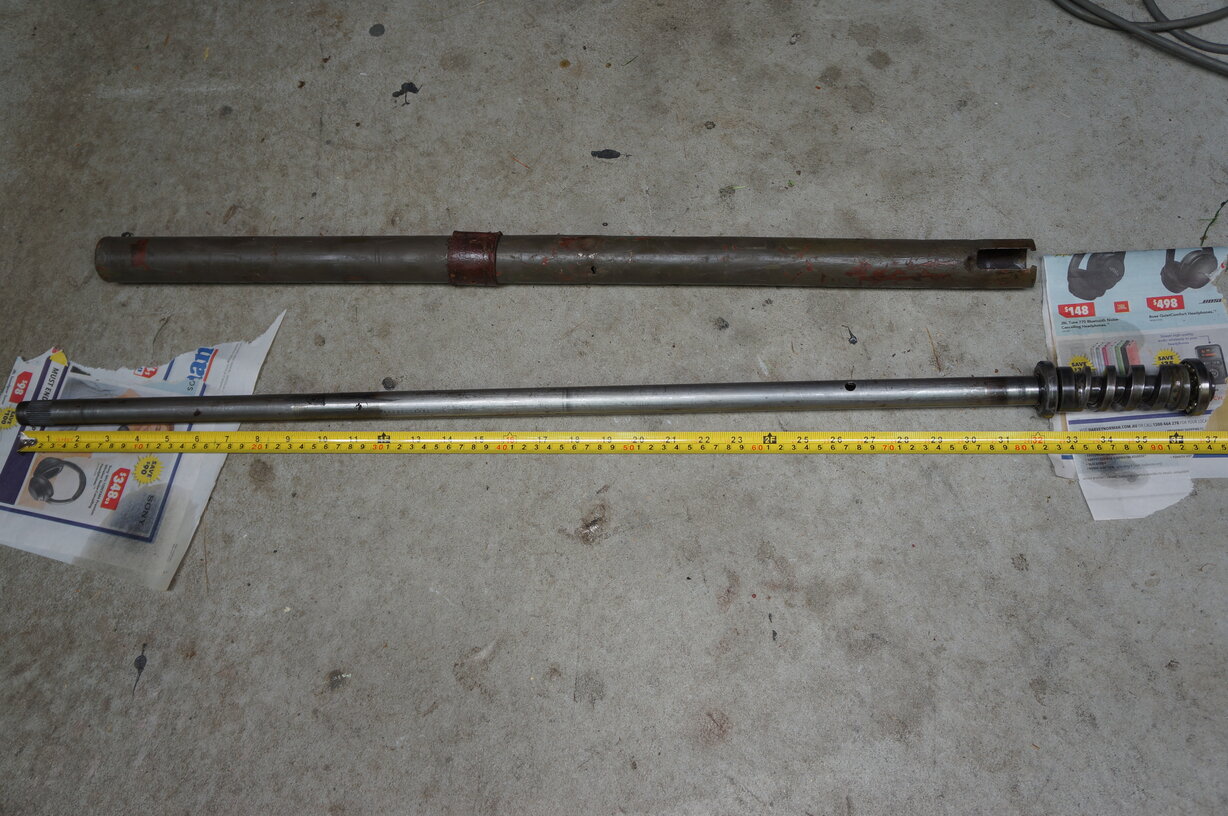
Steering shaft is 37" instead of 40.5". Steering column has been
cut where the horn brush would be mounted.
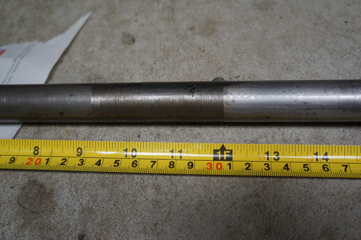
With the steering column out (after removing the battery and its carrier), the whole story became clear. I was rather surprised to find the steering column was 37"! I wasn't aware of any Jeep model using that length. Then I noticed how the steering column had been clamped to the steering box. It had been clamped where the horn brush connection is located on the MB/GPW. The steering column had been cut and shortened! Closer examination revealed the shaft had been cut and welded.
Cut short and welded back together.
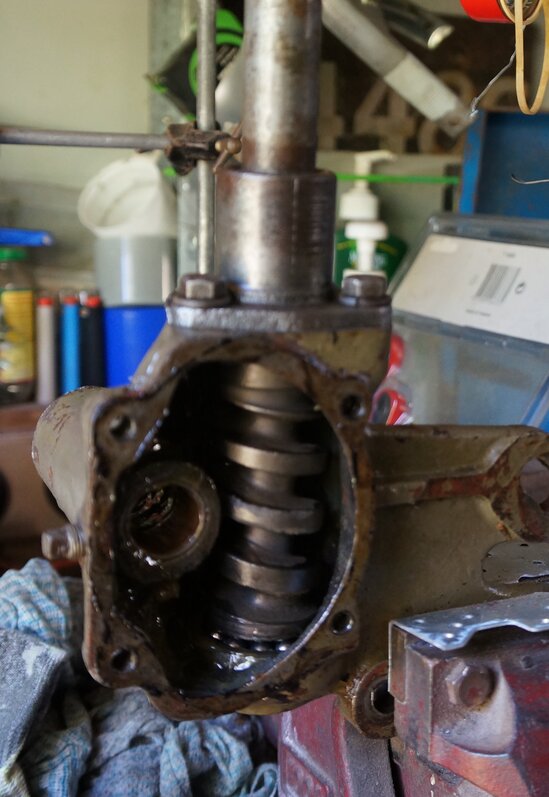
I examined the worm drive. Yes, it did look like there was some wear.
Wear visible 2nd groove from the left.
After all of that, there was no doubt the
steering shaft and column had to be replaced. Not just because of the wear,
but with 3.5" removed, it was no wonder the position of the steering wheel
seemed strange. Out of curiosity, I temporarily mounted the column back
in the Jeep, and moved it up 3.5". What a difference! It turned out I didn't
really need the smaller steering wheel.
Why was it shortened is something that
will probably never be known. I have seen this kind of thing done in the
Model T world because the seats are not adjustable.. I can only think a
previous owner was very short.
What to do now? New steering shafts are hideously expensive if you want a good repro; around A$800 by the time one got here from the U.S. Cheaper ones, around $250, are available from India on eBay, but the quality is unknown. There was some mention of the forum of some repros not being made with correct hardness. The local supplier I had been using so far, Milspares, had new ones listed, but out of stock. A phone call revealed they were N.O.S. and had now run out. M.V. Spares didn't have any listed, and another supplier I know of, Marathon Spares didn't have them listed either. However, they do deal with second had parts. I emailed them to tell of my tale of woe, and I was much relieved when a reply came back saying they did have a good second hand one. I ordered it of course, and also a new steering column from Milspares, since Marathon didn't have that.
16/10/25: Steering shaft arrived. It looked in excellent condition.
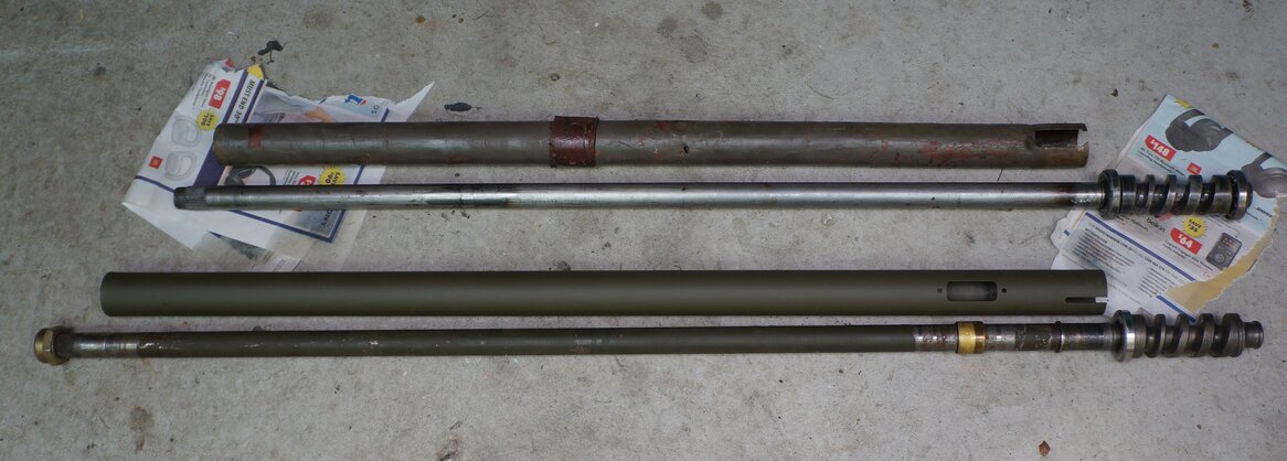
You can see what the problem is here. "Original" column and shaft
at top.
I was pleased to see the 'new' steering
shaft had a hole up the centre of the worm drive so would be compatible
with the CJ horn arrangement. As can be seen in the above photo, the brush
type horn contact was present on the replacement. However, I had to remove
it because it's in the way of the bearing cup and snap ring for the upper
bearings. Also the bearing retainer that the steering column clamps to
wouldn't fit over it. In any case, the CJ setup is much better. There's
more possibility with short circuits or bad contact with the original brush
type horn contact.
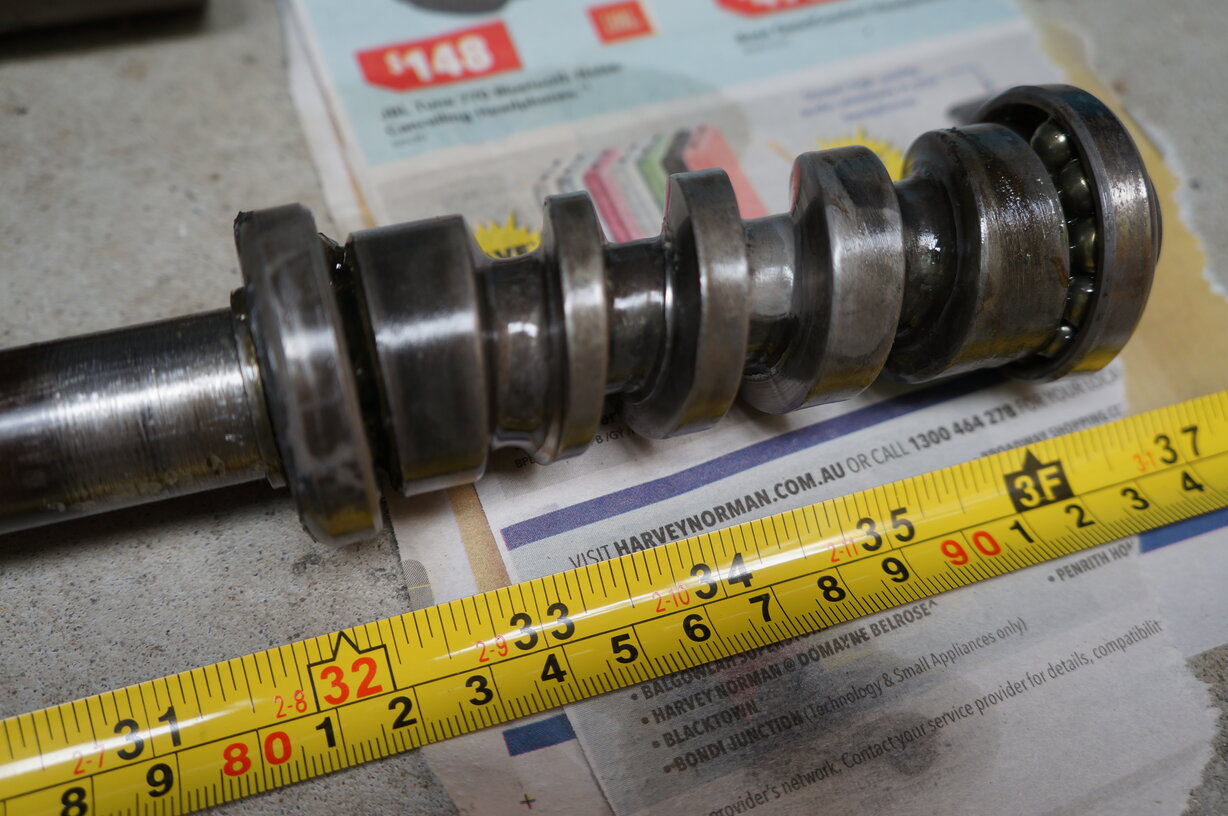
While the upper bearing cup was present,
I replaced it since I had a new one. Similarly, the lower cup was replaced
along with all the ball bearings. I was one ball short (the packet had
previously been opened) so had to reuse one. There was no visible wear
in the originals, but replacing them eliminates that possibility causing
steering play. The bearing cups are held in place with snap rings. It's
a fiddly operation to remove them, but not hugely difficult.
Bearings transferred to replacement shaft. Note horn contact at
left. This was removed.
The next job was to set the bearing preload for the steering shaft. This is done with shims.
Steering box in vice while preload is adjusted.
The shims are adjusted between the top bearing and bearing retainer so that the shaft turns freely, but without any vertical play. I had to remove three shims.
17/10/25: Apply silastic to upper bearing retainer. Reinstall sector shaft - feels like it has a good fit.
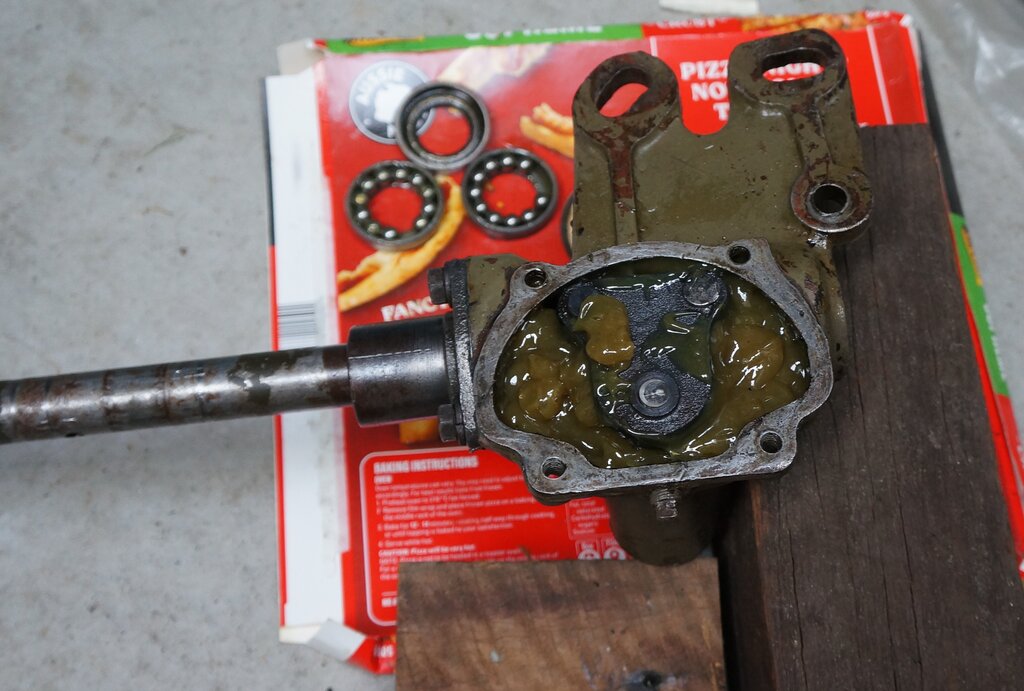
Ready for gasket and cover.
Install gasket and cover. Noted adusting pin has been gouged after I readjusted steering box previously. Will grind the damaged part for temporary use, and replace with next parts order.
18/10/25: Assemble steering column to steering box. Find that the upper steering shaft bearing (at the top of the column) was a tight fit on the steering shaft. Had to hammer it on with a piece of wood. Found that the whole thing can be slid back in through the firewall if the plate surrounding the clutch pedal is loosened off.
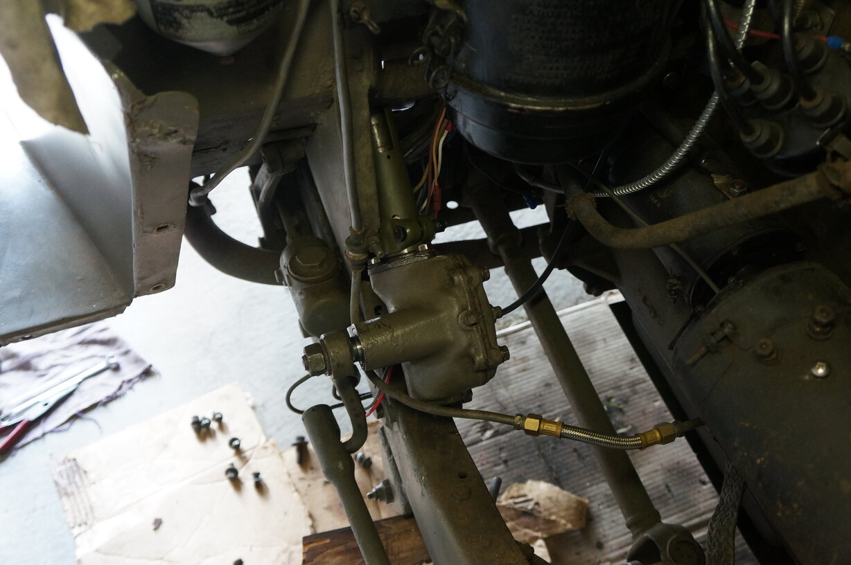
Steering box back in.
The steering was then centred. Counting
the turns of the steering wheel end to end, it was just over four turns.
The steering wheel is then turned two turns so the sector shaft is in the
middle. Then, with the front wheels straight ahead, the pitman arm was
attached.
Pitman arm nut is done up to 100 ft. lbs.
It was found the alignment of the steering
box to the chassis is now slightly different. If the steering box was bolted
flush to the chassis rail as before, the steering column was to the left
on the dashboard side. Some packing (e.g. washers) will be needed between
the steering box and chassis rail to adjust this. For now I've just tightened
it down as is, to get the Jeep drivable.
So, why did the steering box have a better
fit before? It appears the steering column had been bent to suit.
Slight bend in steering column towards the right end.
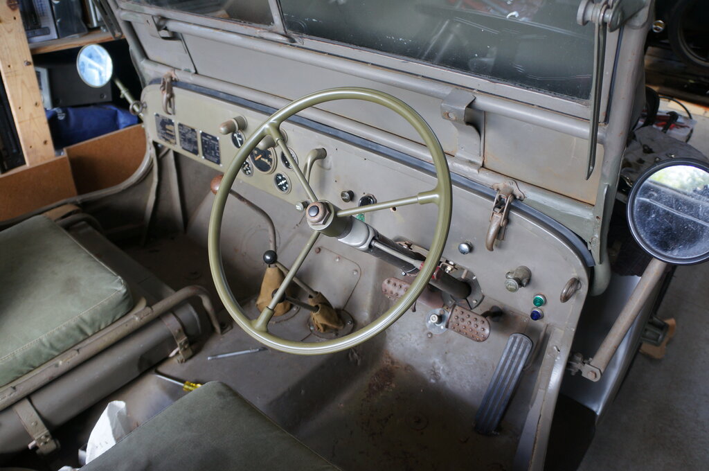
The fender was replaced, and the regulator and battery installed.
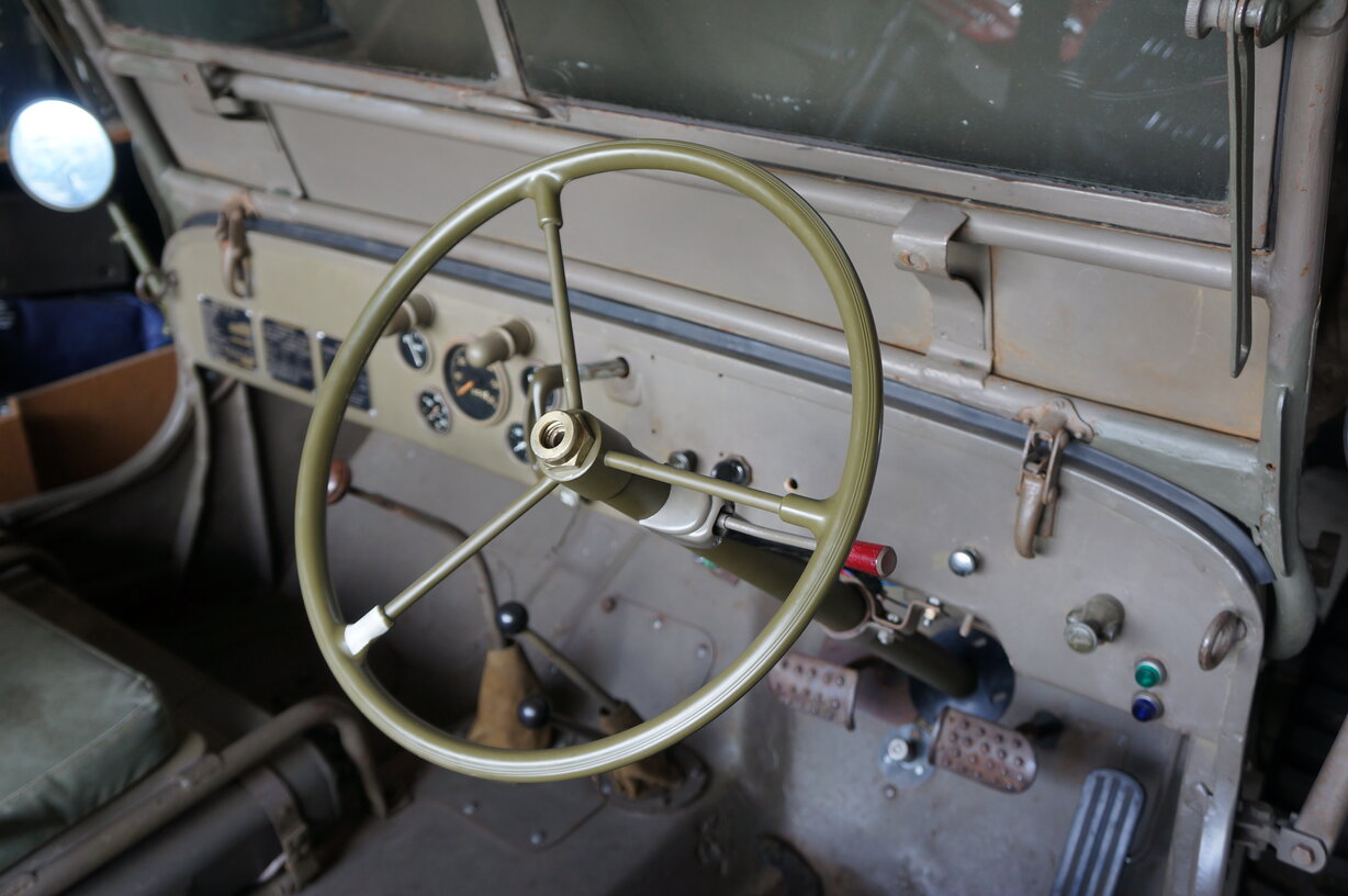
New steering column gives more steering wheel clearance. Horn wiring
yet to be done.
I'm happy with the results. The steering is much tighter and the amount of play is what I would expect. There's not much else I can do if the inspector complains...
19/10/25: Found the brake lights on when I came back home after a day out with the Model T. No idea how long they had been on for, but the battery was 6.22V, so probably not too long. A possibility is the pedal freeplay needs adjustment. If that doesn't fix it, I will make a switch operating off the pedal. I've never liked hydraulic brake light switches.
20/10/25: Found no clearance between brake pedal and master cylinder piston, so readjusted. Switch appears to be working OK now. Left battery maintainer on just in case the brake lights come on all night. Reinstalled horn wiring. Lengthened wire for longer column. Horn switch bad design. Floating metal washer can move to the side shorting against steering wheel nut. I soldered it to the central contact. When threading the wire it needs to come up from the steering box. Remove the outer horn contact from the steering shaft or it will be a pain to get the wire through - I realised this after I did it the hard way.
21/10/25: Improve fitting of steering
box to chassis rail with packing washers. Centre steering wheel rotation.
Install new floor seal for steering column.
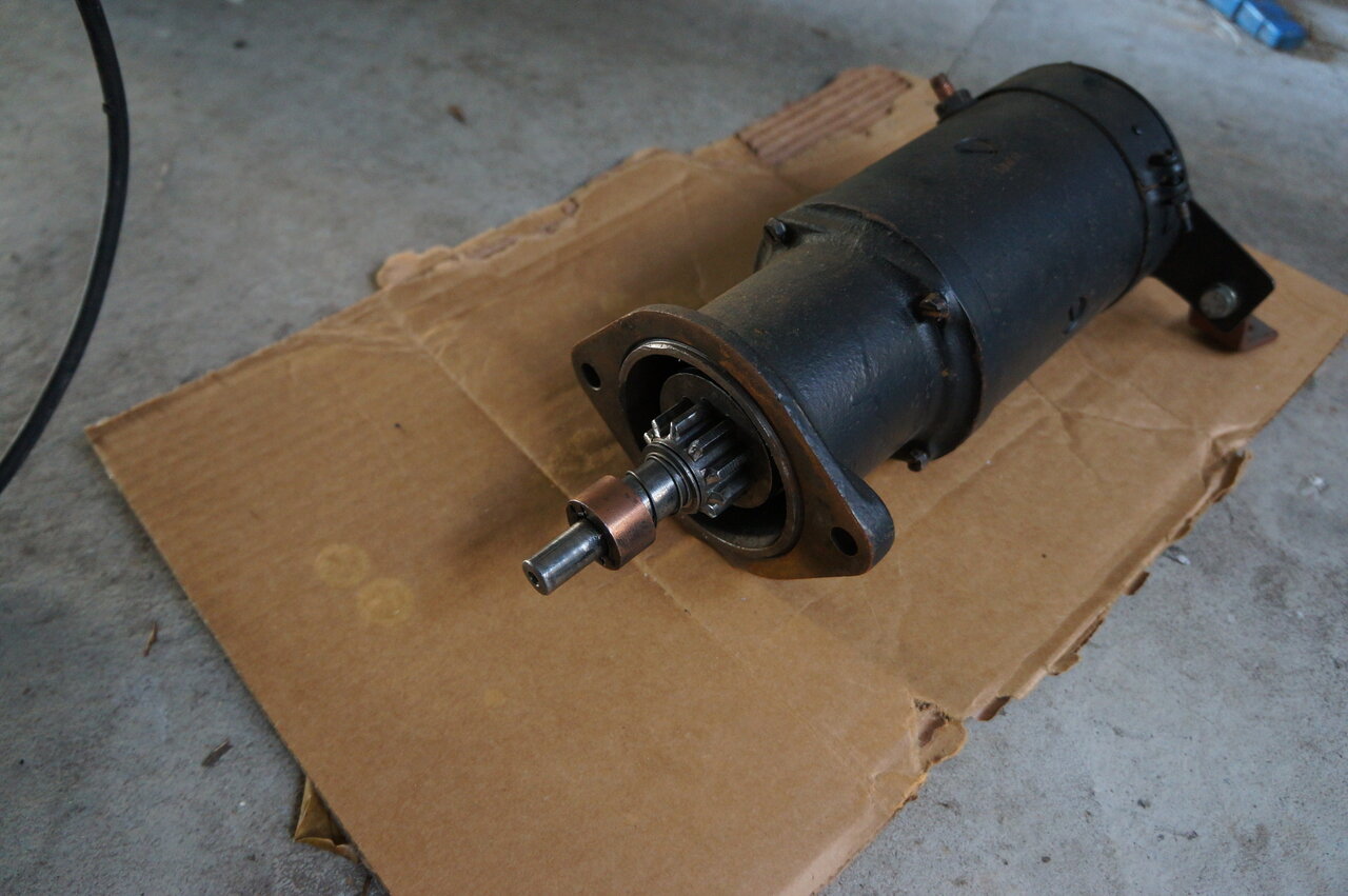
Remove starter motor. Number of teeth is 10 which is correct for a 97 tooth
ring gear. Measure ring gear height which is 5/8" and therefore has 97
teeth.
23/10/25: Ordered new Bendix from Marathon Spare Parts.
29/10/25: Commenced work on Bendix replacement.
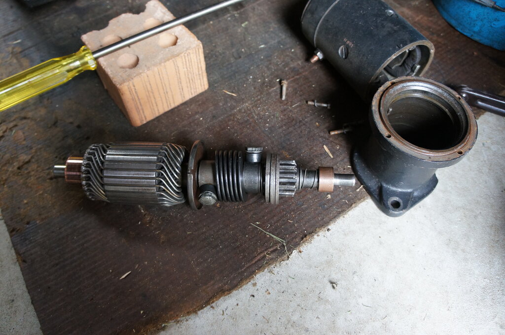
Armature and Bendix extracted from starter motor.
Getting the starter motor out and apart is not difficult. As I noted previously, it all looked in very good condition. I noted the locking tab washers had been reused, since the locking tabs were broken off. Obviously, this had been worked on before.
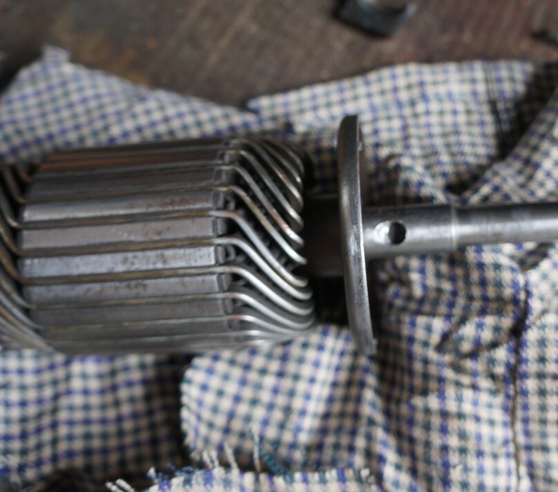
Hole in shaft has been damaged.
Where the bolt secures the drive to the shaft required a little bit of grinding with a Dremel to get the Bendix off. It seems that in the past the bolt might not have been tight, because it elongated the hole in the shaft, with which it engages, and left a burr on the edge.
Hidden under the spring was this broken part.
Once off, we find that looks are not what they seem. Under the spring was the broken part shown above.
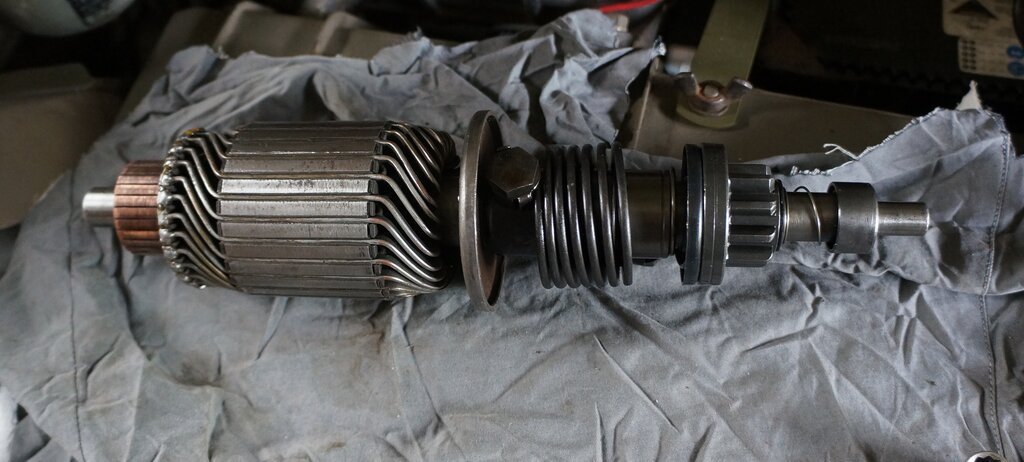
New Bendix installed.
I was impressed with the quality of the
new Bendix. It also had the right number of teeth (10). There are many
Bendix drives supposedly for MB/GPW Jeeps which have 9 teeth. Incidentally,
these always seem to be the cheaper drives from eBay and the like.
10 teeth will give a faster rotation of
the flywheel anyway, even if the 9 tooth versions do actually mesh properly.
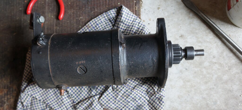
Starter motor ready to go back in.
Reassembling is not difficult. As always,
the brushes need to be held out of their holders while the armature is
reinserted. An interesting feature is a bushing in the bell housing to
support the end of the starter shaft.
This simple job has totally transformed
how the Jeep starts. A nice quiet engagement of the starter every time.
I was amazed at the difference. It's probably one of the most significant
things I've achieved in terms of how it performs.
Anyone who has a Jeep with a grinding
Bendix (including whoever bought the Queanbeayn Jeep), should dismantle
the Bendix and check the drive parts under the spring.
Now is a significant timeline in my work - the mechanical and electrical work is pretty much finished. Only the chassis work with the spring brackets remains.
3/11/25: Put bolts in for RHS front
spring bracket. It appears originally, that for Ford GPW (which my chassis
is), these brackets were riveted as well as welded. Willys MB appears to
have used bolts. The result of this is access is difficult with the GPW
chassis. The chassis is boxed in, and the nearest access hole is a few
inches away. That means one can't just reach inside and push the bolt through.
And, no, there was no chance I was going to use rivets!
First thing to do was make sure the holes
were clear. The one towards the front was, but the rear one needed a bit
of drilling out. For the Willys chassis, the bolts are 3/8" x 1.5" UNF,
and that's what I used here.
Bolt on end of coat hanger wire allows it to be inserted remotely.
I used a short length of coat hanger wire,
looped around the bolt for about 3/4 of a turn. It needs to be tight, otherwise
the bolt will just fall out as you try to get it in the hole. The idea
is then once the bolt is through, and captive with the nut, to push the
wire so it unhooks.
This is the kind of job that is extremely
difficult and irritating unless you've got patience and dexterity. After
some practice, I was able to get the front bolt in. It was a little bit
tight, so pushed down on it with a narrow ring spanner to get it through.
Only enough thread needs to come through to attach the nut, and then the
whole thing can be pulled through. Remember to unhook the wire first! I
pushed on the bolt with a screwdriver, to stop it turning while the nut
was put on. Once the thread came through the other side of the nut, I used
pliers to grip it. As the nut tightens against the spring washer, it stays
still.
Front bolt in position.
The rear bolt went in similarly, but is further from the access hole. I also had to remove one of the steering box bolts first. I was getting good at this by now, and didn't take as long to get in.
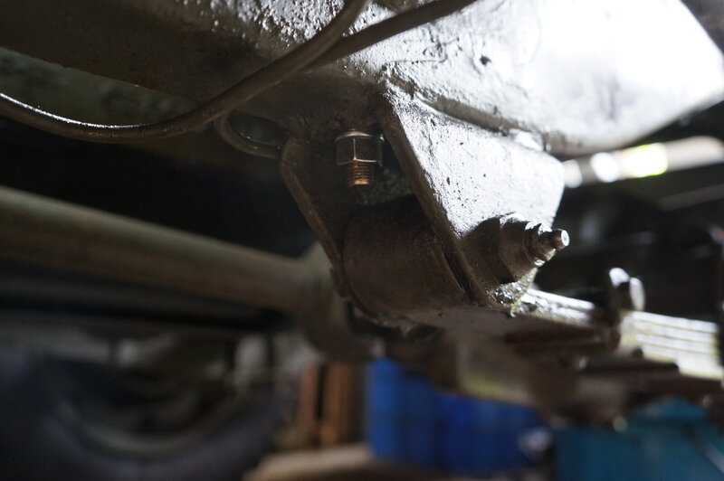
Front spring bracket done!
5/11/25: Weld outside of rear spring bracket. I decided to give it another go - this time practicing on another piece of steel first. I used a star picket since I had one handy, and it's of similar thickness. It turned out I needed more current that what I had been using before. About 80A was right, and made a reasonably neat weld. I found on the Jeep that 95A was about right for the bracket.
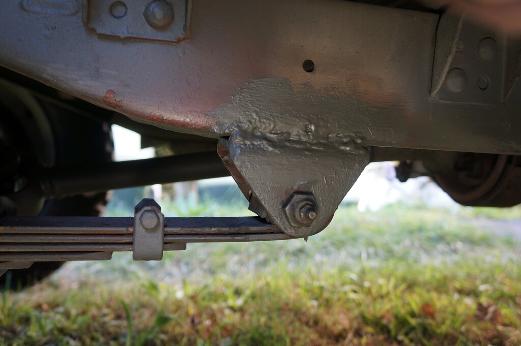
Outside weld done.
6/11/25: Did the weld on the inside of the chassis rail. Check tyre pressures - all down to around 20 psi. Pumped up to 35 psi.
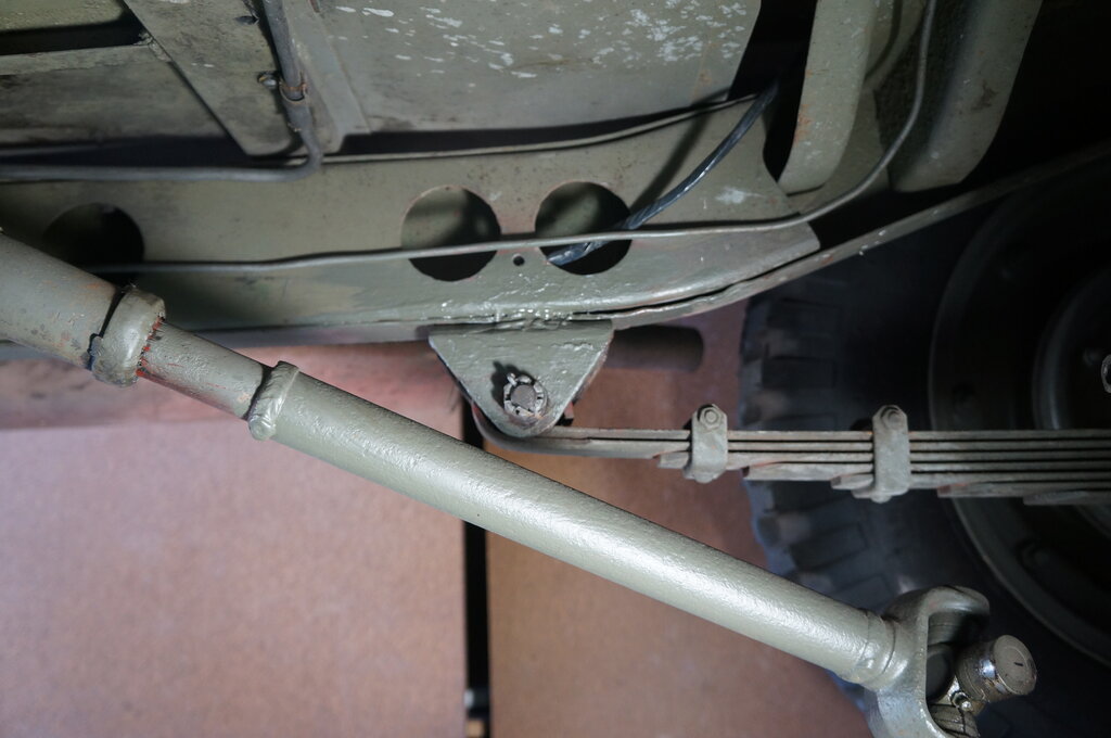
Inside weld. The original Ford weld is only in the middle third
and that's what I've duplicated here.
Now, for the anticipated comments from the 'welding police' - "He can't weld for shit"...Well, it's not something I've ever been trained in. I could say the same when someone has difficulty with something electrical. Anyway, the bracket is welded, it's strong, and it should pass registration.
7/11/25: Replace missing grease nipple on LHS front of rear spring. It is 1/8"-27 NPT. I obtained replacement from Pirtek. Painted welds.
8/11/25: Grease chassis. The difficult
part of this was the grease gun developing air locks from when I refilled
it. Very messy!
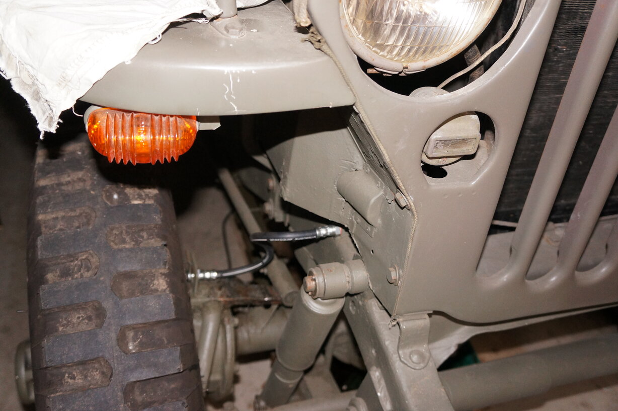
Move black out marker light connection
to rear park light connection on headlight switch. As originally connected,
the B.O. markers went off when the headlights were on. For civilian use,
where the B.O markers take the function of parking lights, it's best to
have them on with the headlights. We want all the visibility possible!
Paint steering arm where the paint had
been dissolved by brake fluid.
Check engine oil.
Check oil in both diffs.
9/11/25: Check transfer case and
gearbox oil levels. Like the diffs, these use 9/16" square head plugs.
It turns out I have the early Willys gearbox, since the plugs are on the
RHS. Later were moved to the LHS. I can see why - the access is awful.
However, I did manage to open the fill plug by using an 11/16" ring spanner
to get it to initially loosen. Then used an 11/16" socket on an extension
to fully undo it. Fortunately, it didn't need any oil added.
Check water level - OK for now but could
do with a flush.
10/11/25: Enquiries made about registration
with a private car club, and have started the paperwork process. It seems
like a good scheme, although of course there is a restriction of 60 days
per year.
Pink slip (registration inspection) booked
for 14/11/25.
14/11/25: Pink slip inspection.
All went well. My first time driving the Jeep in traffic. The steering,
brakes and clutch are all completely natural - I was operating them without
even having to think. I have to get used to the gear shift pattern - first
and reverse needs to become second nature. But, I didn't stuff up too badly.
The return trip was good - got it into third gear.
All the really hard work is done, and
next is the back and forth bureaucracy of the registration and club paper
work.
19/11/25: Replace tool box locks with lockable type. MV Spares was the lowest cost source of these.
23/11/25: Modify dash lamp shields by widening the slots. This is to improve gauge illuminination - previously non existant. Cleaned plastic back window in roof. This roof is an Australian type, since it has provision for side curtains, as well as having the plastic window insert. Normally, there is a square hole with no plastic.
8/12/25: Registered at last! I went to Katoomba this morning to hand over the paperwork, which was accepted without any problem, and a new set of plates and a log book were handed to me.
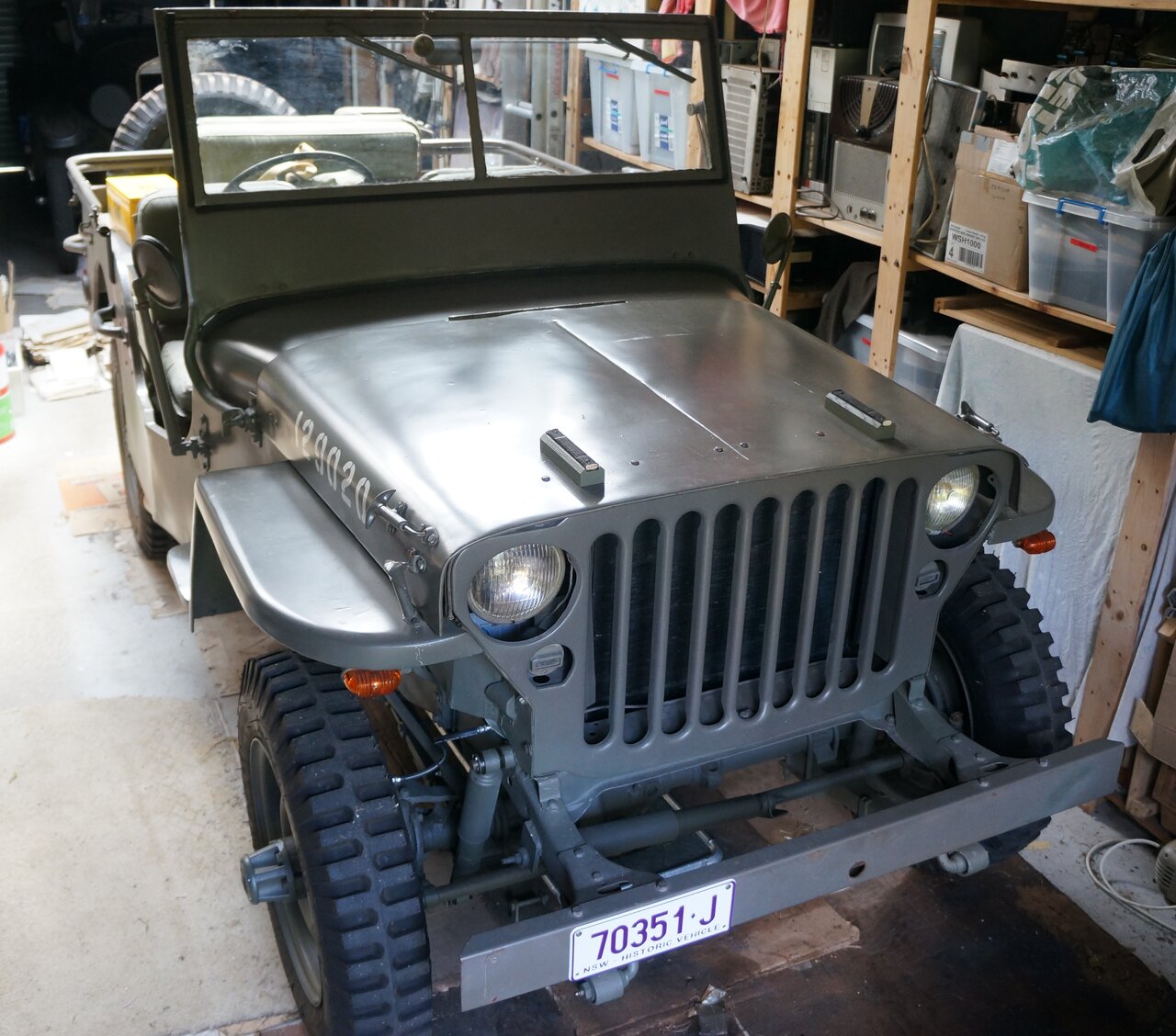
My first experience with historic registration.
Registration has always been the most unpleasant aspect of owning cars. Not fuel prices or the cost of insurance - no, it's getting them registered. It took over a month to get the Model T registered because of a pedantic inspector. This time, with the Jeep, a problem existed with paperwork, with each bit of paper having a different make and model. The previous owner called it a Ford GPW on the receipt because he thought that the Ford was more desirable and valuable. Problem is, it says "Willys" on two parts of the body; one quite obvious (the data plate). The previous Victorian registration was as a Willys MB. Then, the pink slip called it a "Jeep" GPW. None of these names or models are incorrect as such, but when a cop pulls me over and sees Willys, it's a problem if it's registered as a Ford. Also, the registration people are going to be confused when across the paperwork it's Ford GPW, Jeep GPW, and Willys MB. Not knowing anything about Jeeps, you can imagine how the pedantic nature of the public service is going to react to that. Anyway, after much correcting of paperwork, it all went through OK. Now, for the next few jobs - battery isolator and tyre flaps.