Prior to my acquisition, the Jeep had been
fitted with indicators, as part of its adaptation to civilian use. The
indicator switch was a Hella 4208, which I was familiar with, since I used
this on the Model
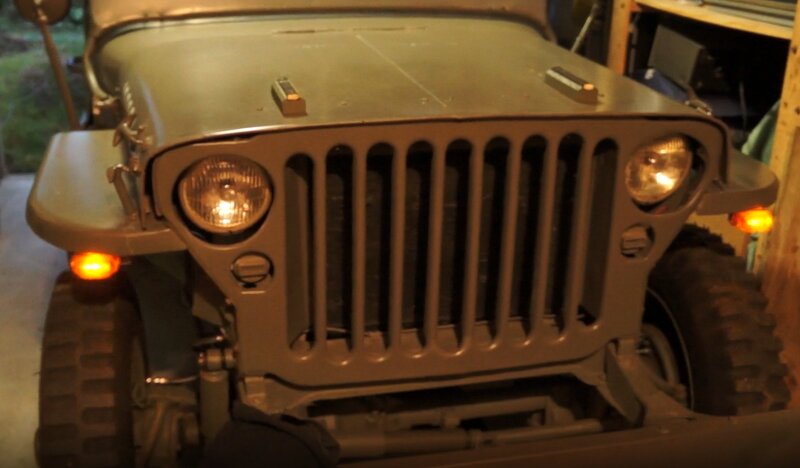
T. The front indicators were 18W festoon bulbs in Hella fittings, and
the rear were a modification of the existing lights. The lens cut outs
had been enlarged, and amber lenses fitted. Installed were 3W BA15S bulbs.
Additionally, a green panel lamp had been mounted on the dash, to remind
the driver when the indicators were in use. The flasher was a thermal 3
pin Tung-Sol UP229D. Vintage electronics enthusiasts will recognise Tung-Sol
as being a large manufacturer of valves in the U.S.
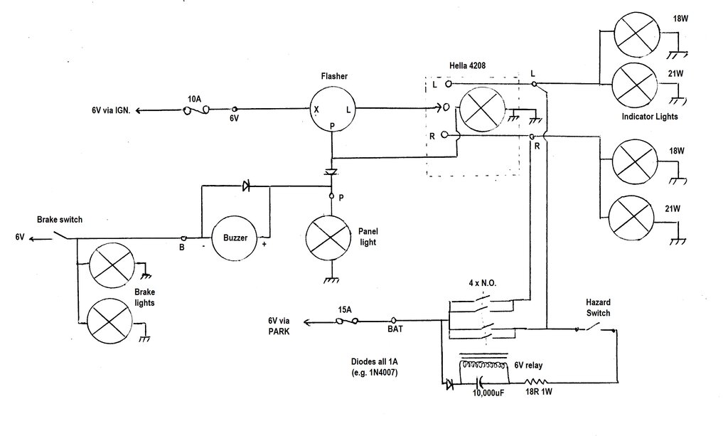
The circuit was a simple one, thus:
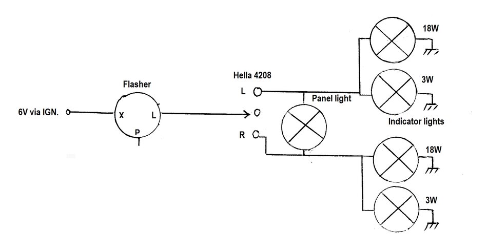
Circuit of indicators as I bought the Jeep.
The Hella 4208 switch contains a pilot light at the end of the switch lever. This had not been connected. The switch comes with a 12V bulb by default, but a 6V type is available to replace it. I was curious how well the thermal flasher worked on 6V. As it turned out, it was perfect, and there was no doubt about retaining it. I was already used to the 4208 switch, so that too would definitely be staying. However, two things needed attention. I wanted the light in the indicator switch to work, and also a buzzer to remind me when the indicators were in use. In bright light, it's easy to overlook the pilot light. First thing to do was to replace the bulb at the end of the switch lever, with an appropriate 6V type. I actually used a side contact bulb normally used for telephone work, and soldered it in. The method of earthing the original wedge based bulb looks unreliable.
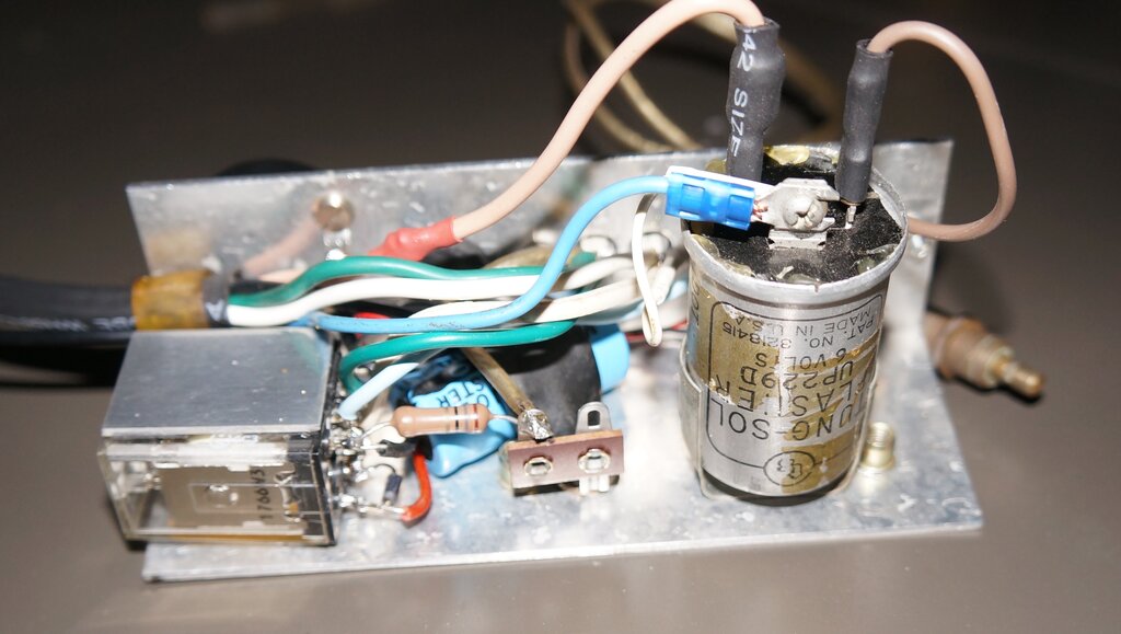
Thermal Flasher.
A brief description of how the circuit
works is in order at this point. Heart of the circuit is the flasher itself.
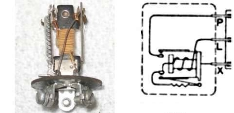
Typical thermal flasher and connections.
The flasher terminals are labelled "X" which is the supply; 6V in this instance. "L" is the output to the lights, and "P" is the pilot light. Two terminal flashers do not include the "P" terminal. When the indicator lights are switched on, current flows from terminal "X", through a heating coil, a low resistance relay coil, and thence to the lamps, via terminal "L". The resistance of the heating coil is high enough that the lamps do not emit a visible glow. The heating coil is wound around a bimetallic strip which actuates a set of normally open contacts. These are connected across the heating coil. The sequence of operation is that the lamp current heats the bimetallic switch, which closes, connecting the lamps to the supply causing them to light at full brilliance. However, in so doing, the heating coil is now shorted out and it cools down. The contacts open, the lights go off, and the coil heats again. This cycle repeats as long as current is applied.
Pilot Light.
Three terminal flashers allow for a pilot
light; typically mounted on the dash, or in the instrument cluster, where
the driver can see it. The bulb is typically about 1W. When the indicator
lights are on due to the thermal contacts being closed, the current relay
switches its own set of normally closed contacts, between terminals "X"
and "P". Why is there separate switching for the panel light? That's because
to simply connect it to terminal "L" would cause sufficient current flow
to not only permanently illuminate the bulb, but would also disrupt the
normal operation of the thermal relay, since it would always be heated
to some degree.
Why not just use a two diode OR gate to
power the pilot light from which ever set of indicator lights was flashing?
Yes, indeed you could. But remember, indicator lights were invented well
before suitable diodes existed. There is another way to power the pilot
light, which doesn't require the third terminal, and is as old as
the design of the flashers themselves. It's how my Jeep indicators were
wired. Refer to the first circuit, and note the pilot light is simply wired
between the actives of the left and right indicator lights. It can be seen
that if the left lights are switched into circuit, current will flow into
the left indicator bulbs, but also through the pilot light, and the right
set of bulbs to earth. Because the indicator bulbs are of much higher wattage,
virtually all the voltage drop is across the pilot light. This lights at
full brilliance, but the right indicator bulbs show no illumination. The
operation of the circuit is the same when the right indicator bulbs are
selected.
The circuit is simple and works well.
However, there's two important points to note. First, the pilot bulb must
be floating. Its socket cannot have one terminal earthed. Also, the polarity
of the bulb reverses, depending on which side is selected. This is not
important with incandescent bulbs of course, but anyone contemplating using
this circuit with a LED pilot light will need to include a bridge rectifier
(unless built into the LED bulb).
The Hella 4208 switch requires one side
of the pilot light to be earthed, so cannot be used with the two terminal
flasher circuit. It must be used with a three terminal flasher.
Insufficient Current.
Since the flasher was the three terminal
type, then it should be simple to connect the light in the switch to the
"P" terminal, and also the panel lamp and buzzer. Alas, when I tried this,
it didn't work. It seemed odd that nothing was coming from the "P" terminal.
There was no choice but to open the flasher can to see why. It's soft aluminium,
so was able to bend back the crimp without damaging it. The problem was
visible in that the contacts on the "P" relay were not quite touching,
even though the thermal relay was working normally. My immediate thought
was to simply bend the contacts so that they would touch, but it just seemed
odd that there was no evidence of wear. Thinking about it a bit more, this
was a current relay. What if there wasn't enough current flowing through
it? And that's what it was. Adding another light bulb to the load caused
the "P" contacts to connect.
This is when I learned that incorrect bulbs had been fitted to the rear lights. The bulbs were only 3W! Hardly even bright enough (or safe) to use as indicators. Indicators should be bright as possible, so I installed 21W bulbs. Now the "P" terminal worked! It appears this actually might be a deliberate design feature, to alert the driver if one of the bulbs has blown. The remaining bulb will still flash, but the pilot light won't. With that sorted, the rest of the circuit could proceed.
New Circuit.
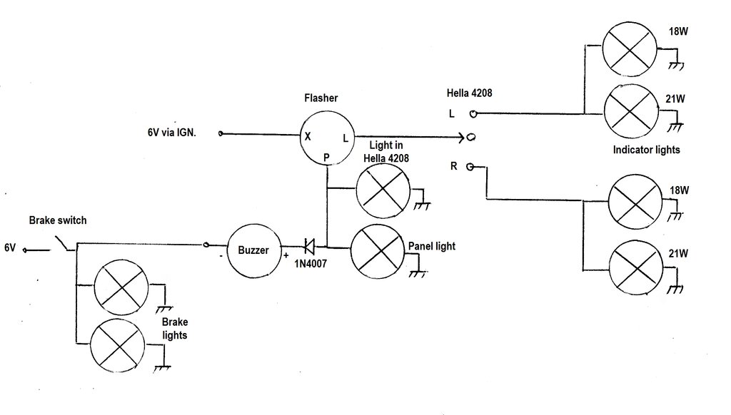
Buzzer and indicator switch light now operative with this circuit.
10A fuse in series with 'X' terminal not shown.
The panel light was retained, since it was already there and the hole drilled in the dash. Besides, it's actually more effective having both lights visible. The buzzer circuit is such that the buzzer is silenced when the brakes are actuated. It can be irritating while waiting at traffic lights listening to it. Although it was not intended as part of the design, it does confirm the brake light switch, and at least one of the brake bulbs is working.
When the "P" terminal goes high, current flows through the diode, into the buzzer, and then to earth via the brake lights. Since the buzzer current is minuscule, no voltage is lost across the bulbs. Therefore, the buzzer sounds in time with the flashing. Now, if the brakes are actuated, there is +6V across the brake light bulbs. It can be seen that with +6V at both buzzer terminals, there is no voltage to operate the buzzer, so it is now silent.
The diode prevents the buzzer seeing reverse
polarity, which could damage it. This would happen when the brakes are
actuated, but the indicators are not. In this instance, +6V appears at
the buzzer negative terminal, and the positive terminal is earthed through
the panel and indicator switch light. The diode prevents this. Even if
the buzzer was non polarised, the diode is still required, since it would
sound whenever the brakes were actuated without the indicators flashing.
This circuit worked well, and was used
for a few months. As the rewiring of the Jeep continued, as part of the
tidying up, I wanted to make a proper flasher module which included hazard
lights. I also had ideas about using the panel light to also show the brake
light switch was working at all times.
A Digression - The Ignition Switch.
A theoretical circuit was designed, but
when I went to test it, I had to rethink the whole thing. The intention
was for the hazard lights to only operate in the "Accessories" position
of the ignition switch. The indicators until now had operated from the
"Run" position. Supplying them from the battery feed isn't a good idea,
since someone could actuate them when parked unattended. Not only could
this drain the battery, but would also attract attention. Operating the
hazard lights from the "Run" position was not a good idea, since it would
mean possibly damaging the ignition coil. It must be remembered that hazard
lights are likely to be used when the engine is not running.
It turns out the ignition switch fitted to my Jeep is meant for a diesel tractor; in particular one of a number of Deutz models. Tracing out the connections revealed there was no "Accessories" position as such.
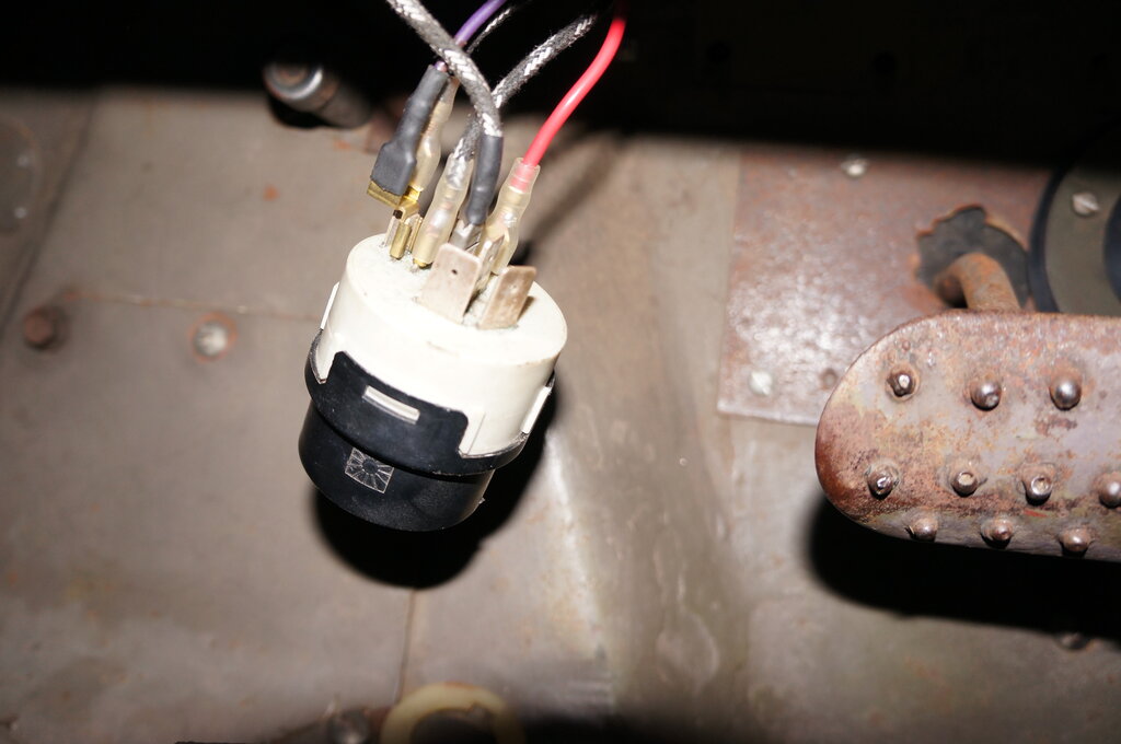
Ignition switch is meant for a diesel tractor.
I'd always known it wasn't original, and had assumed it was from some industrial or agricultural machinery. After all, where Jeeps were fitted with a key switch, it was a simple one position type. This was modern with multiple positions. The only identification was "Germany" and "51120". Searching for this led me to a Sparex S36014, and the ignition switch for Deutz 6507, etc. Eventually finding the contact diagram, along with my own testing, revealed something quite new to me.
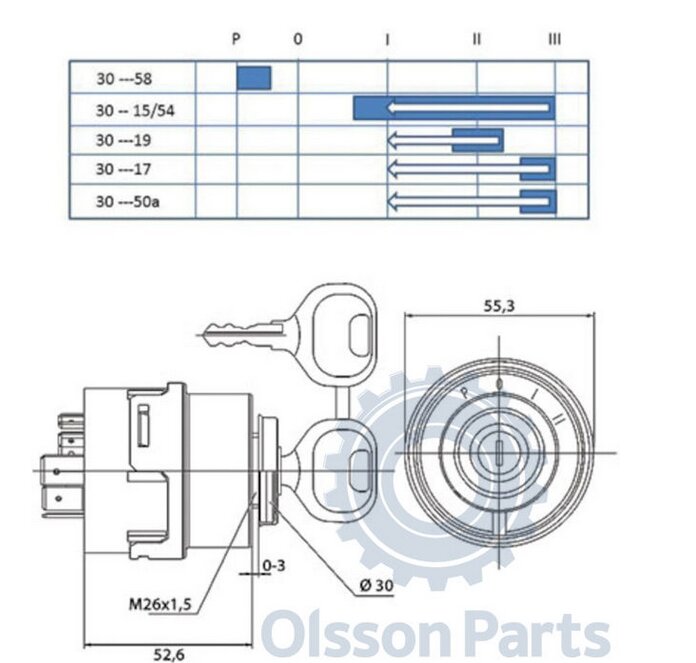
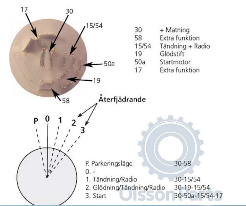
Mysteries of the ignition switch revealed.
The way the switch had been wired was so
that the coil was connected to 6V in the "1" position. I had been using
"P" as the "off" position since it was furthest to the left. I had until
now just assumed that "0" would therefore be for accessories. Except there
was, electrically, no such thing. It hadn't even occurred to me that it
might be a diesel switch, and what the differences might be.
Strangest of all is the "P" position,
which means "Park". It appears this is for parking lights. Not sure why
a tractor would need those, and/or why they'd be operated through the ignition
switch. "0" is as would be logical, is everything off. "1" is "run" and
for the fuel solenoid. "2" is spring loaded. With a normal switch, that
would be "start", but here it's glow plug pre-heating. A second spring
loaded position, "3" is what finally actuates the starter motor.
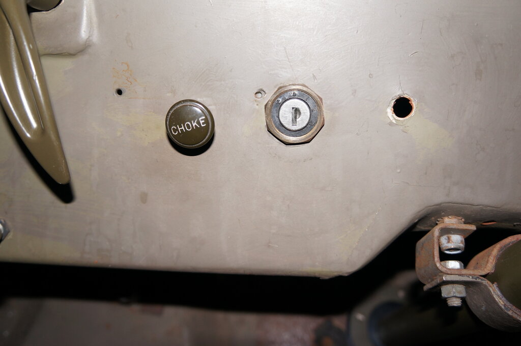
Front of ignition switch. Hole to the right was later filled
with a spare switch.
To get back on topic, it would seem necessary to use the "Park" position to run the hazard lights. Since "Park" is disconnected in "1" (run), it meant having two separate circuits; one for the indicators, and one for the hazard lights.
Final Circuit.
Final circuit provides hazard lights.
The indicator circuit itself is the same as the second version, but with a modification to the panel light and buzzer circuit. Now there is a two diode OR gate to operate the panel light, either from the brake switch, or the "P" terminal on the flasher. The panel light illuminates whenever the brakes are actuated, or when the indicators are flashing. The buzzer works on the same principles as before, but now it's wired across the brake switch diode. When the indicators are flashing, 6V is present at terminal "P", at the panel light connection.
The buzzer sounds in the usual way. The
diode across it is reverse biassed and has no effect. If the brakes are
actuated without the indicators flashing, the diode becomes forward biassed,
and the panel light illuminates. In this instance, the buzzer does not
sound, since, 1) the diode being forward biased shorts out the buzzer,
and 2) without the diode, the buzzer would be fed with reverse polarity
and wouldn't work anyway, possibly being damaged. Incidentally, the buzzer
is an electronic type with a piezo electric transducer.
The diagnostic features are therefore
is one up on the previous circuit, in that the brake switch is tested every
time the brake switch is actuated, not just when the indicators are used.
Hazard Lights.
To operate the four indicator lights from
the flasher could overload it. As it is, each side draws 39W (6.5A). My
initial idea was to use the hazard switch to actuate one side and a slave
relay to operate the other. This wouldn't fit in with the no accessories
position on the key switch, so I developed a completely separate circuit.
This is really just an add on to the normal indicator circuit. A relay
drives each side separately. In actual fact, the relay used has four contacts,
but these are paralleled in sets of two, so it functions as a double pole
switch.
The supply is fed from the Park position,
so the hazard lights require the key, but without the engine running.
The relay itself becomes the flasher. Here,
the coil is wired like a shunt drive vibrator, except with an RC time constant
to obtain a much lower frequency. This circuit is connected across one
set of contacts, so the relay coil is fed via the lamps. The 10,000uF charges
up via the 18 ohm resistor, and when the voltage is sufficient, the contacts
close. The lamps illuminate, and at the same time, the supply to the RC
time constant is lost. The 10,000uF holds the relay coil in for a short
period of time, and then it releases, causing the cycle to begin again.
The diode is necessary to isolate the
coil circuit when the contacts are short circuited. When the contacts are
shorted, the capacitor discharges only through the relay coil, giving a
longer hold time than if the 18 ohm was also in circuit.
The hazard light switch itself could be in any number of places. Connecting it in series with the relay coil means it's subjected to much less current than if it was in the actual supply to the whole thing. Incidentally, it's important to remember the current draw is not a continuous 13A, because of the duty cycle. Roughly this is 50%, so the average current is closer to 6.5A. The "Park" position could actually be used to switch the hazard lights, but as I have plans to use that as a de-facto accessory position for the future radio, the separate switch was required. Besides, there were already two switch positions in the dash looking for a use.
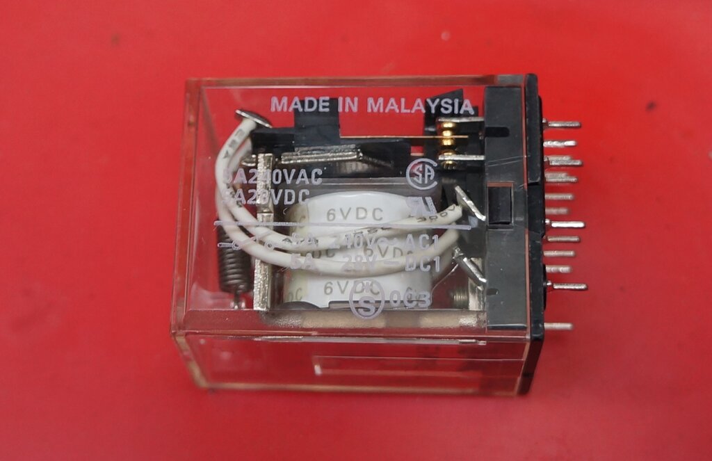
Omron relay used.
For those wishing to duplicate the circuit, the relay used is an Omron MY4-02. Coil is 6V DC with a resistance of 36 ohms. Contact rating is 5A at 28V DC or 5A at 240V AC. With two sets of contacts paralleled, the switching current is not necessarily 10A, since it cannot be guaranteed each contact will close at exactly at the same time. However, the 6.5A drawn would be well within such ratings. Flashing speed is controlled by the 18 ohm. A wirewound rheostat can be used to adjust this. It only needs a 1W rating. Other relays will probably need some experimentation here. The circuit can be, of course, used as a substitute for the usual thermal flasher if one should not be available. The flash rate is however voltage dependent, and this may have to be adjusted as a compromise, for when the generator is charging and when it is not. In the hazard application, the generator is not charging, so the speed can be fixed for the normal battery voltage.
Installation.
Chassis with flasher and relay.
I built the circuit on a chassis with a terminal strip to connect into the electrical system. The indicator switch was fed with a cable with a 6 way Molex connector. This makes removing either unit easy.
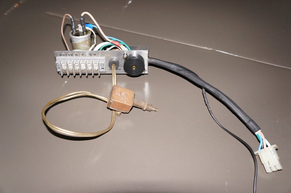
Hazard switch shown. Note the Molex connector for the indicator
switch. Separate black wire is earthed under mirror bolt.
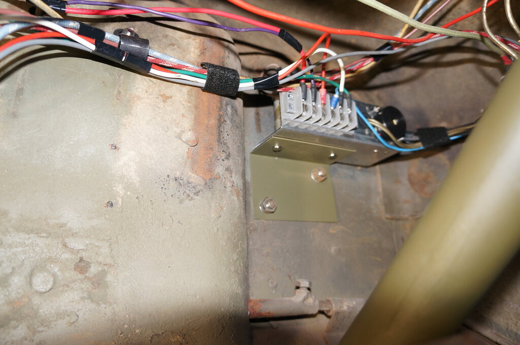
All mounted in position.
To mount the chassis to the firewall, I
made up another bracket from steel, which I painted in olive drab. This
is mounted under two of the nuts securing the fuel filter. The chassis
is secured to this via two 4mm screws which go into Rivnuts on the chassis.
Removing it is a simple matter without
having to undo the fuel filter nuts.
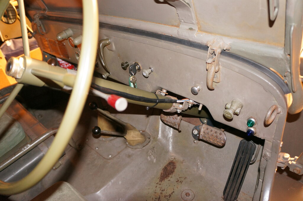
What was the old wiper switch (chrome knob) is now the hazard
light switch. Note the hole to the right of the ignition switch has also
been filled. The green panel lamp is at the right of the dash. Note the
red end of the indicator switch - there's a bulb there too.