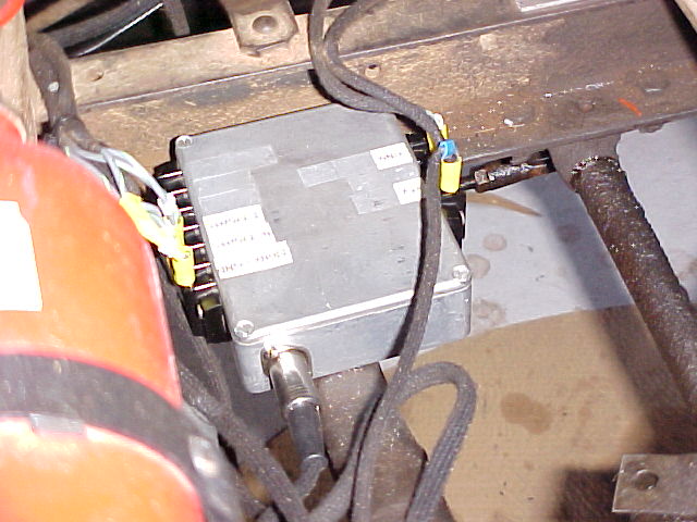
The flasher circuit is built in a diecast box bolted onto the chassis cross member. The terminal strips on the sides go to the lights and power, while the DIN plug connects the indicator switch.
While it is not compulsory to have indicators
and brake lights fitted to vintage cars in Australia, I thought it wise
that my Model T should have them. Few understand hand signals. So, I decided
to fit signal lights others would recognise.
I decided to take a different path to
everyone else, and design my own flasher unit. 6V flashers are available
from all the vintage parts suppliers, but I wanted something more tailored
to my requirements, and to avoid the limitations of thermal flashers.
The flasher circuit is built in a diecast box bolted onto the chassis
cross member. The terminal strips on the sides go to the lights and power,
while the DIN plug connects the indicator switch.
Advantages of Electronic Design.
An electronic version would eliminate
the heavy wiring to the indicator switch, and also provide a user adjustable
flash rate. Some examples of 6V indicators I've seen seemed to suffer from
an excessively long "off" period and dim lights.
Since the voltage supply for the oscillator
is regulated, flash rate is constant over the normal voltage range of the
battery voltage.
Unlike thermal flashers, this design does
not depend on correct lamp wattage to function properly. Thermal flashers
operate by virtue of a heating wire and bimetallic switch. As the lamp
current passes through the heating wire, it heats up and causes the bimetallic
switch contacts to touch. This shorts out the heating wire and full voltage
is applied to the lamps. The bimetallic switch cools and the process repeats.
It can be seen that the time taken for the heating wire to actuate the
bimetallic switch depends on the current flowing through it, and thus the
lamp wattage. This often causes problems when LED's are used instead of
incandescent bulbs. To overcome this problem, load resistors can be connected
in parallel with the LED's to increase the current draw. However, this
detracts from the efficiency aspect of using LED's.
LED Indicator Lights.
While LED's and vintage cars may appear
to be a contradictory combination, there is actually a lot of interest
in using them. By default, this flasher is ideal for LED's because the
performance is not affected by their lower current draw, and circuit completely
breaks the supply to the lights in between flashes. It is possible to modify
commercially made 12V or 24V LED signal lights to run on 6V, as the individual
LED's run on between 2 and 4V. To do the modification, you'll first need
to power up the light on its intended voltage, and measure the current
through each chain of LED's, (usually around 20-40mA) and see what the
actual LED voltage is. The 12 and 24V lights have series/parallel wiring
where groups of several LED's are in series with one current limiting resistor.
The LED's need to be rewired so each has its own resistor. This will allow
6V operation. To calculate the resistor required, use the formula R(in
ohms)=(6-Vf)/If, where Vf is the LED forward voltage, and If is the LED
forward current. Quarter watt resistors will be adequate. Bear in mind
that some units may be difficult to get apart, and also some micro-surgery
on the PCB will be required.
The Circuit.
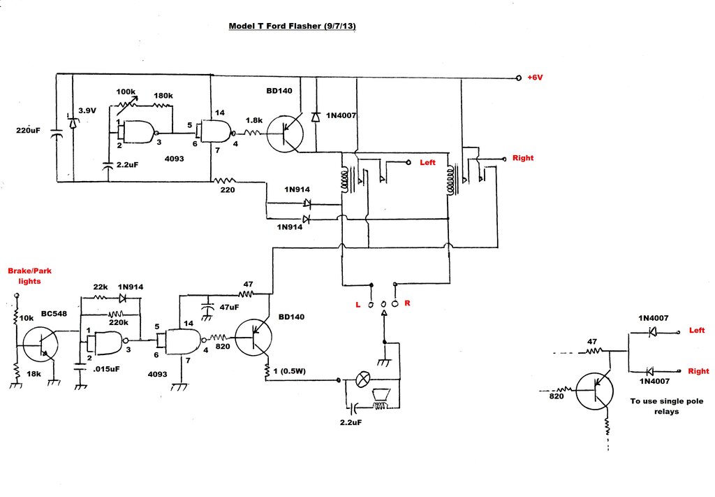
Circuit is based on two CMOS IC's and two relays. It eliminates
all the troubles of thermal flashers and provides audible warning.
The flasher circuit is a Schmitt trigger
oscillator built around a 4093 CMOS quad NAND gate, which then drives one
of two relays. The normally open contacts of these relays switch the left
and right side indicator lights. The appropriate relay coil is switched
by the indicator switch. This is simply a two way switch with a centre
off position.
The supply for the 4093 is stabilised
at around 3.9 volts with the zener diode and 220 ohm resistor. While CMOS
logic gates are happy with supply voltages from 3 to 15, the supply does
need to be regulated so that the voltage of the car electrical system will
not affect flash rate. I like to design for a 5 to 7 volt operating range.
This allows for when the generator is charging, and also if the car is
stopped and other loads are drawing current.
A second oscillator provides an audible
tone from a miniature speaker so that the driver knows to cancel the signal
when required. Additionally, to prevent having to listen to the beeping
tone while waiting to turn when stopped, it is muted when the brake is
applied.
Flasher Details.
The 4093 gates are simply wired as inverters
with the output fed to the input via a resistor. There is also a capacitive
time constant at the input. Assume the circuit is first powered up. The
2.2uF capacitor will be discharged, meaning 0 volts at the input. Because
the gate is an inverter, the output will be high at around 3.9V. Current
flows via the 180K and 100K pot to the capacitor which starts charging.
At a certain point, the input will see a high, thus switching the output
low. The 2.2uF now starts discharging through the resistors, and so it
keeps oscillating.
Unlike commercially made flasher units,
this one is adjustable. So, you can select your preferred flash rate simply
by changing the RC time constant, hence the 100K trimpot.
As the CMOS gates can only supply about
20mA, a BD140 power transistor is used to drive the relays. The diode between
emitter and collector bypasses back EMF when the relay coils turn off.
I prefer this method to the usual one of wiring the diode across the coil
as it means the transistor won't be damaged if the diode shorts, and the
transistor is also protected against reverse polarity. The back EMF is
absorbed by the power supply.
I discovered during the design that different
types of 4093 will result in different flash rates. I'm using a CD4093BCN.
If you use an MC14093BCP you'll need to increase the resistance. Start
with about 1.5M, or increase the capacitor value.
Note that the 220 ohm current limiting
resistor is in the negative supply to the zener diode and 4093. This is
done because a PNP transistor is being used to drive the relays, and therefore
the 4093 positive rail must be at the same voltage as the transistor's
emitter.
So that the oscillator isn't running all
the time when the indicators aren't being used, there's a two diode OR
gate connected to the indicator switch which completes the earth return
for the 4093's supply. I used 1N914's in view of the low current, but just
about anything can be used.
Audible Warning Circuit.
With my original design, a buzzer was
connected in parallel with the pilot light on the end of the indicator
switch. However, I found its operation to be unreliable because it was
actually a 9V buzzer. The pilot light and buzzer were switched with the
extra relay contacts.
I wanted a reliable buzzer, but also one
that would cease operating when the brake was applied. A slight problem
was to have the buzzer in the same location (under the indicator switch),
while being able to switch it independently of the pilot light. It would
require a separate wire run up to the switch. This was inconvenient.
So, how to run both the light and buzzer
supply through the one existing wire, but operate the light separately
to the buzzer?
I designed an ingenious scheme where the
buzzer would be a speaker running on AC, at about 1KHz. This would also
power the pilot light (6V 1.2W) located at the end of the switch lever.
When it was desired to silence the buzzer it was only necessary to change
the supply to DC. This would be blocked from the speaker via a capacitor,
and thus have no effect.
The heart of this circuitry is another
Schmitt trigger oscillator, except running at a high frequency. There will
be noticed a diode in the feedback circuit. This changes the duty cycle
so that the "on" time is about 90% and the "off" time is the other 10%.
The reason for this is so the pilot light runs at the highest power possible,
thus maintaining its brightness, but still providing an AC component to
drive the speaker.
Another BD140 switches the pilot light
current. In series with the emitter is a 1R resistor. This is necessary
only to act as a fuse and protect the transistor, should there be a short
circuit around the indicator switch wiring. The speaker is connected across
the pilot light, at the indicator switch. The 2.2uF blocks DC from the
speaker voice coil.
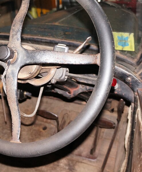
The speaker can be seen mounted to the underside of the indicator
switch.
Silencing Circuit.
When the brake is applied, 6V from the
brake light circuit is fed into the BC548 via the base resistor circuit.
This shorts out the .015uF and stops the 4093 oscillating.
Pin 4 stays low, turning on the BD140,
sending 6V to the pilot light. It has no effect on the speaker which does
not respond to the DC because of the series capacitor. In my Model T, the
brake light is also the park light running at reduced voltage. It can be
seen that the indicator buzzer will also be silent with the headlights
on. However, the pilot light is quite visible in the dark, so no audible
warning is required.
Relays.
These are double pole units with 6v coils.
The ones I used were actually 4PDT units with a coil current of about 200mA.
The indicator switch determines which coil is activated simply by completing
the earth return of the required relay coil. In the centre position neither
coil is selected and the indicators are off. The second set of contacts
simply switch the supply to the audible warning and indicator switch pilot
light circuit. Obviously, the contact rating must be able to handle the
current for both the front and rear bulbs. For the 10W bulbs I used (20W
total), the current is just over 3A. A contact rating of at least 5A would
be advisable; 10A preferable. The relays I used were 5A rated per contact,
and these were connected in pairs to increase the rating to 10A.
Hazard Lights.
I haven't shown it in the circuit diagram,
but this design makes it convenient to add a hazard light switch. Simply
add a small DPST switch in parallel with the indicator switch, with the
common contacts connected together and earthed. Of course, a SPST switch
could be used with the addition of a two diode OR gate instead.
Construction.
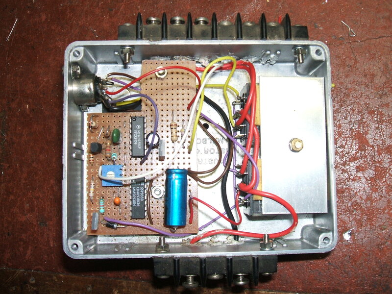
Circuitry and relays fit in a small zinc diecast box.
The circuit was constructed on a small
piece of veroboard and placed along with the two relays in a zinc diecast
box. This was then mounted on the front chassis cross member. A convenient
hole already existing to mount the box. A bakelite screw terminal block
connects to the indicator lights and 6V supply, and a 5 pin DIN socket
used to connect to the indicator switch. Miniature multi core cable was
run to the switch. The Canadian version of 1926 Model T has a tube running
up the steering column for the horn switch wires. I used this same tube
to run the indicator switch wires...something you couldn't do had the indicator
switch been wired the conventional way carrying the full lamp current through
thicker wires.
The indicator switch used is a Hella 4208.
I paid about $74 from Scott's Auto 1, back in 2003. Repco wanted about
$128! It is a far superior product to the metal chrome plated switch that
all the repro parts suppliers sell, which is of very flimsy construction.
Postscript 2026: The Hella 4208
is obsolete, and appears to have been for a few years now.
A tiny PC mount speaker was mounted on
the underside of the switch, with the 2.2uF blocking capacitor mounted
inside the switch body.
The actual indicator bulbs I use are 6V
10W BA15S. I use 1929-31 Model A rear lights with the dual coloured lens;
red for brake and parking and amber for indicator. The front lights are
small motorcycle lamps I got at a swap meet.
The golden rule with 6 volt electrical
systems is to run a separate earth wire from each light directly to the
negative battery terminal. Don't rely on rusty chassis connections. If
you have good connections and use wire with an appropriate current rating,
your lights will work as well as those on a 12V car.
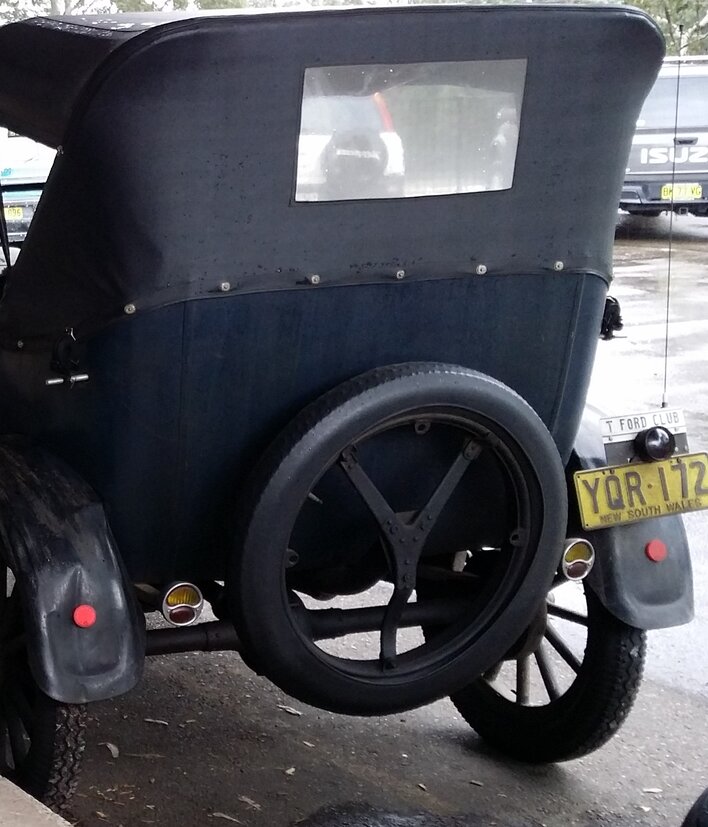
Model A rear lights are used. The red lens is for the brake and
park lights, and amber for the indicators.
Front indicator lights are a non-descript accessory for motorcycles.
These ones were obtained from a swap meet and are unbranded.
Modifications.
If the audible warning is not required,
the circuitry around the second 4093 and BD140 can be eliminated. The pilot
light then connects directly to where the emitter of the second BD140 was
connected.
If the pilot light as well as the audible
warning is to be eliminated, the relays can be single pole types.
A simpler audible warning can be had by
connecting a 6V buzzer across the pilot light, and eliminating the 4093
and BD140 circuitry as above. The buzzer will always sound when the indicators
are operated.
The silencing circuit can be eliminated
by removing the BC548 and its base resistors.
Single pole relays will often be easier
to obtain, and the circuit can easily be adapted to use them. In place
of the second set of contacts, a diode OR gate is fed from the left and
right indicator lights, and thus provides supply to the pilot light and
audible warning circuit when the indicator lights are actuated.
12 Volts.
The circuit is adaptable quite easily
to run on 12V. It's simply a matter of selecting appropriate relay coils.
The other components are rated in excess of 12V so no modification is required.
The 3.9V regulator needs no modification. However, given that the CMOS
IC's are rated at 15V, it is wise to connect a 15V zener diode across the
supply pins of the tone generator IC. That is, across the 47uF capacitor.
This will prevent any high voltage spikes damaging the IC.
Components.
To those outside of Europe and Australasia,
the transistor types may seem strange. The BD140 can be replaced by any
general purpose PNP transistor which can carry 1A. The BC548 is an NPN
small signal transistor, and it can be replaced by anything similar; the
collector current is so low as to be unimportant. In both cases, the supply
voltage will not exceed the ratings of any likely transistor that you choose.
The 1N4007 diodes can be replaced by any
of the 1N400x series - again the voltage is very low, and anything from
1N4001 upwards will do.
Note the comments previously concerning
the 4093. If your 4093 seems to operate at the wrong frequency, some experimentation
with the RC time constant will be required.
All resistors, with the exception of the
1R pilot light resistor can be quarter watt. Most of the values are not
critical, and one or two values either way should be OK. The exception
is with the resistors connected between 1,2, and 3 of the 4093.
Similarly, the capacitors are non critical,
except for those connected to pin 1 and 2 of the 4093's.
For the buzzer, I used a miniature PCB
mounted 8R speaker.
The pilot light is a 1.2W 6V bulb (200mA).
If the power rating of this needs to be increased, the associated BD140
may need to be upgraded, and the 1R resistor increased in power rating.

Hella indicator switch with pilot lamp.