This made the transfer case removal and installation very easy.
Contrary to what the service manuals recommend,
it is quite possible to remove the transfer case from the Jeep, while leaving
the gearbox in situ.
Doing so means a lot less weight to deal
with, not having to disconnect and drain the radiator, and dealing with
the chassis cross member.
Removing the transfer case will allow
access to the gearbox shift rails, without having to remove the gearbox.
In this instance, one of the shift rails was to be replaced, along with
the poppet balls and springs.
In the case of a cramped garage with limited tools, removing the transfer case on its own first, should make it easier to then remove the gearbox, if required. This is because you are dealing with two lighter objects rather than one large heavy one. Once the transfer case is removed, most of the work is actually already done for removing the gearbox.
Procedure:
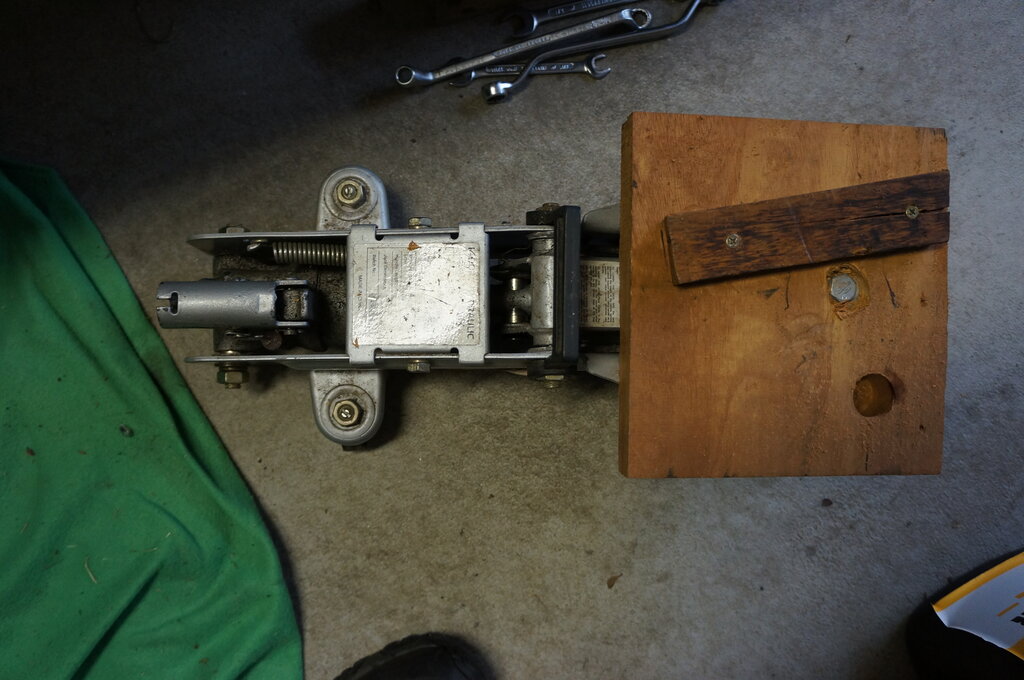
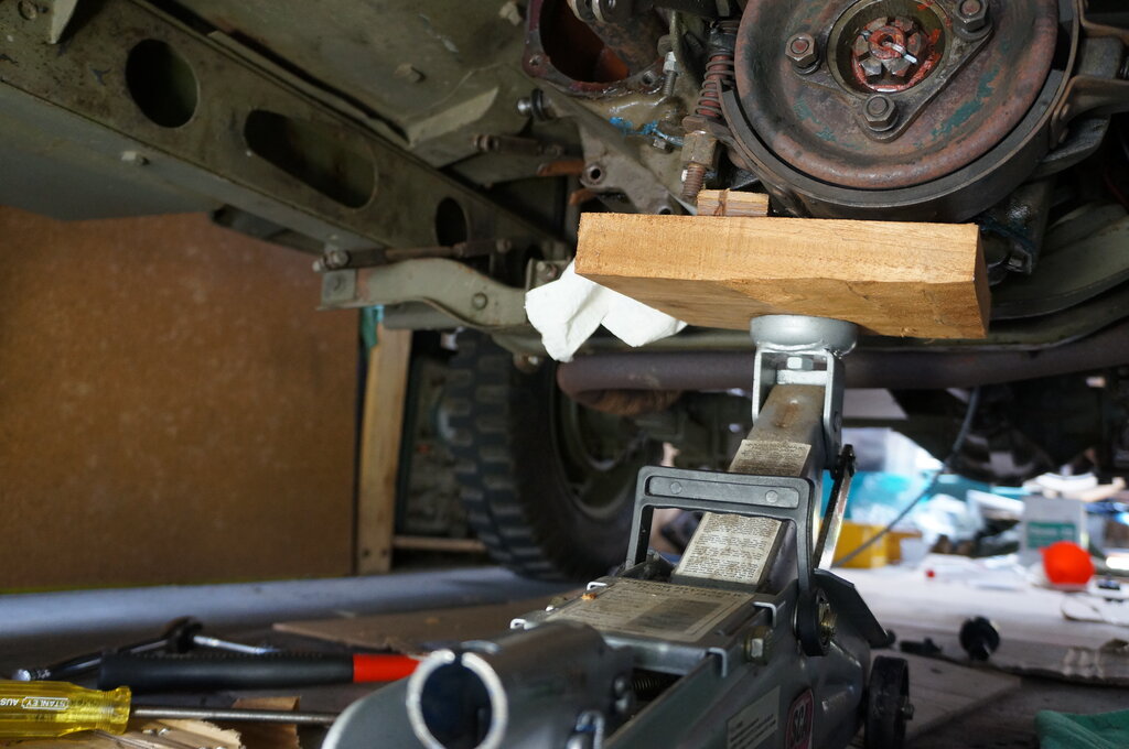
First make up platform for jack. A hole
locates the drain plug and allows bottom of transfer case to sit on the
platform, not on the plug. Another piece of wood supports the transfer
case at the required angle.
This made the transfer case removal and installation very easy.
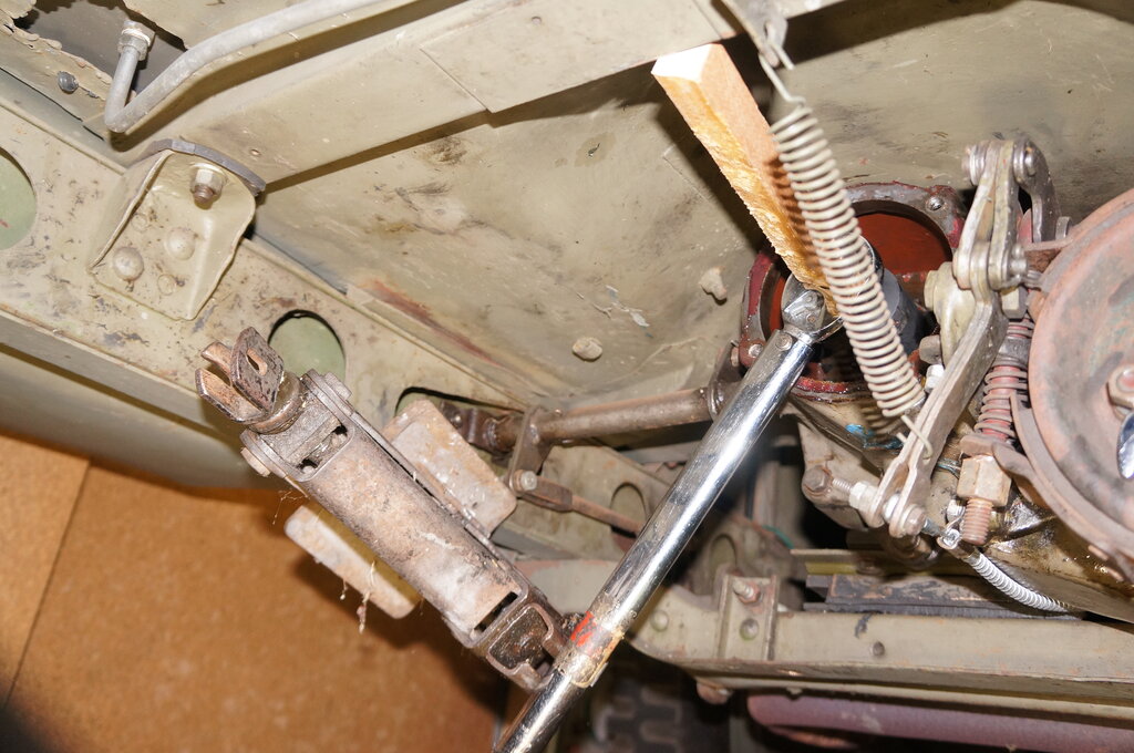
1. Remove transfer case shift levers. Remove Zerk fitting on pin. Remove set screw and push pin as far as it goes, then remove levers. Necessary to remove top of transmission so pin punch goes in far enough. Enough clearance available is available to get levers out.
Remove left side shift lever first.
2. Remove PTO plate (inspection cover) from back of transfer case (9/16" bolts).
3. Remove rear drive shaft, and lock up handbrake drum with spanner against chassis. Apply handbrake.
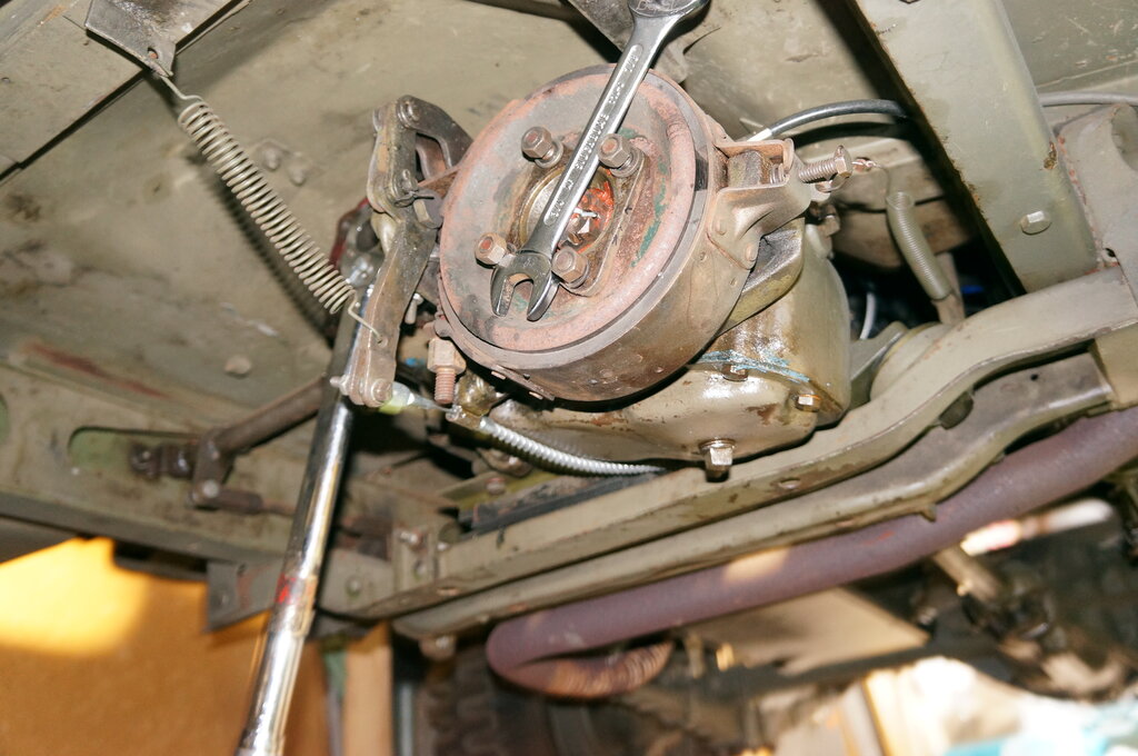
The handbrake won't hold the transfer case gears against the torque
necessary. Lock up the brake drum to prevent rotation.
4. Undo mainshaft nut. Use 1-5/16" socket on torque wrench, with piece of wood jammed in between it and chassis rail to keep it from coming off. Use a jack between chassis rail and torque wrench to undo it. In my example, it felt as though the nut was done up to more than 100 ft. lbs.
A lot of torque required!
5. Remove front drive shaft at transfer case. Leave attached to differential.
6. Remove speedo cable.
7. Remove bolt from transfer case rubber mount 3/4" nut, 15/16" bolt.
8. Clamp clutch cable at bellhousing. I used a welding clamp.
9. Remove clutch actuation tube from chassis rail.
10. Drain transfer case.
11. Drain transmission by syringe from top - easier than getting to drain plug.
12. Remove rear drive shaft from differential - you'll need the space under the Jeep.
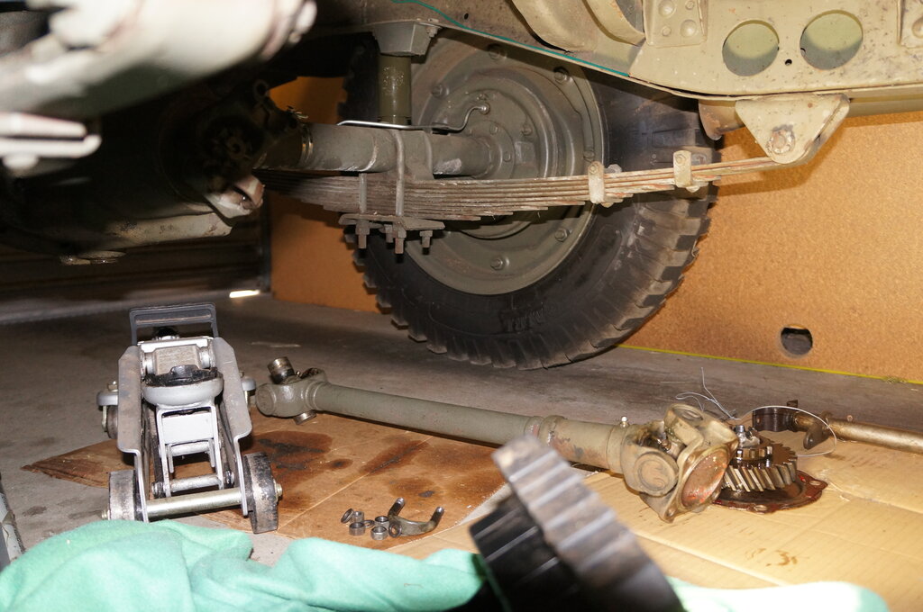
You'll need the space, so best to remove the drive shaft completely.
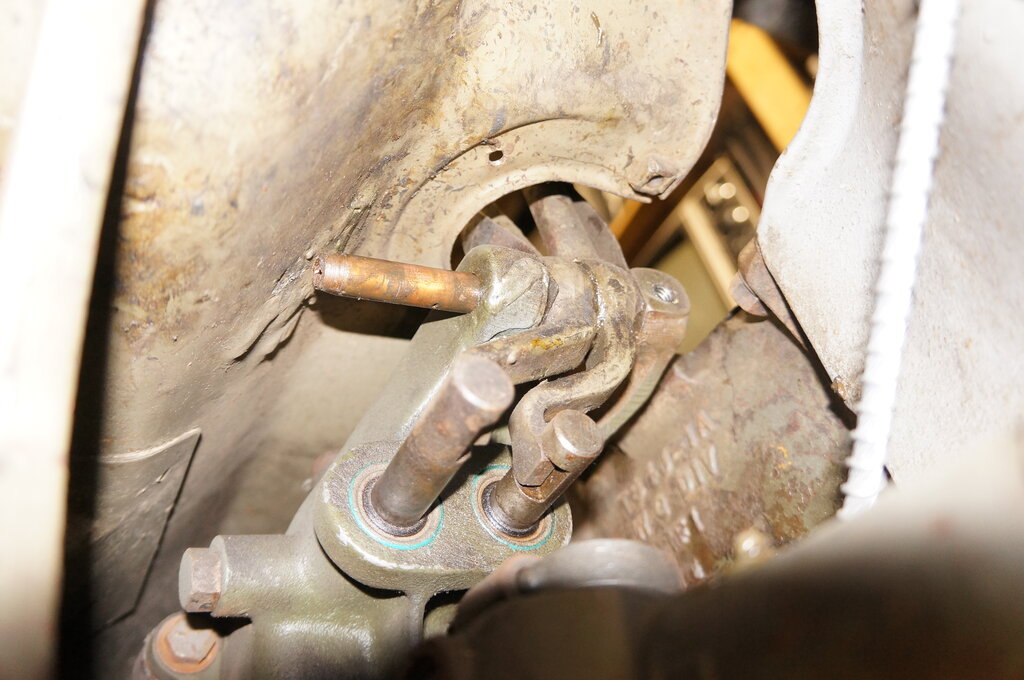
13. Remove transfer case bolt on front next to where front drive shaft attaches. This is one of five bolts (all 9/16") which secures the transfer case to the transmission. Extension and uni-joint needed. This one has a copper washer since the thread goes into the transmission.
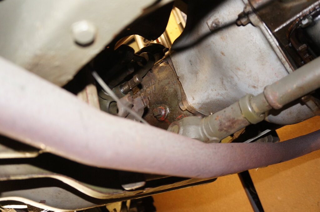
Note driveshaft resting on cross member. One of the transfer case
bolts is between the fill plug and front driveshaft take off.
14. Put transmission into 1st gear.
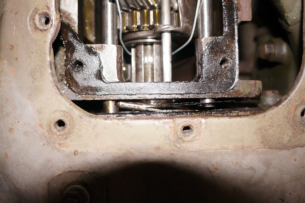
15. Wrap wire around mainshaft, drawing
it tightly against the two front top cover bolts in the transmission.
This is so the mainshaft doesn't come
out when transfer case removed (otherwise the needle bearings fall out
where it goes into the input shaft).
Put into 1st gear and secure the mainshaft.
16. Loosen remaining 4 bolts, just with a few turns still in.
17. Support on trolley jack. Much ease is had if the jack has a platform shaped to fit the bottom of the transfer case.
Wood platform made for the purpose helps greatly. It is bolted to
the jack.
18. Prise gently from transmission slightly with screwdriver. Be careful not to let the mainshaft move back.
19. Remove remaining 4 bolts. Upper right is difficult to get at and needs an extension and uni-joint. Left side bolt 2nd up from bottom also has a copper washer.
20. Transfer case can be prised just far enough to get interlocking pin out with a thin magnet.
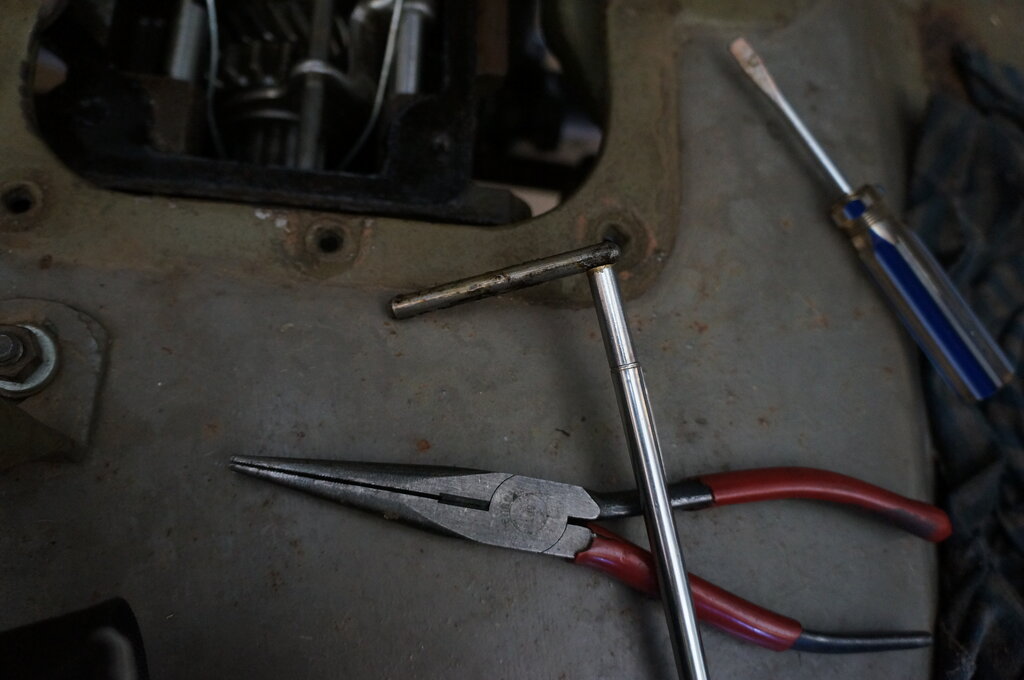
Magnet removes interlocking pin.
21. Place steel tube over mainshaft so it bears against the inner race of the bearing.
Mainshaft bearing is mostly supported by the transfer case. Steel
tube allows mainshaft bearing to be gently tapped out.
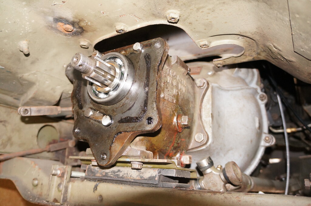
22. Tap gently with large hammer as transfer case is slowly pulled back. Check frequently that bearing has not been pulled too far from transmission. Transfer case will come free.
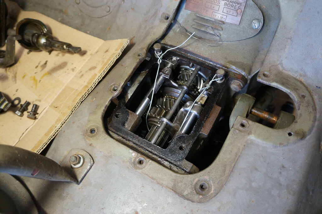
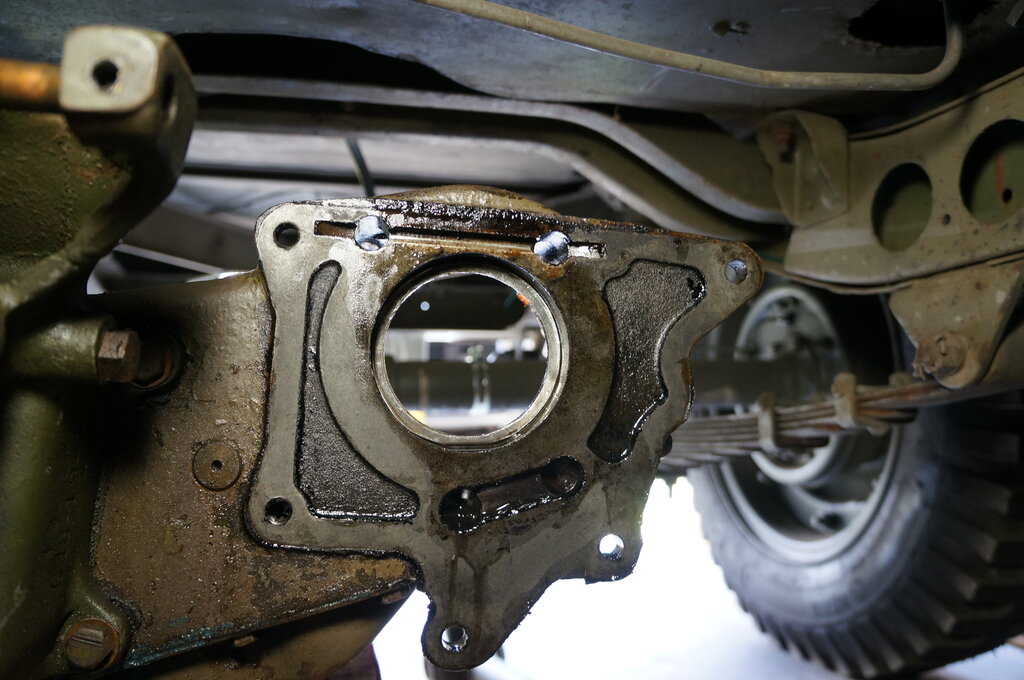
Rear of gearbox. Shift rails accessible at top.
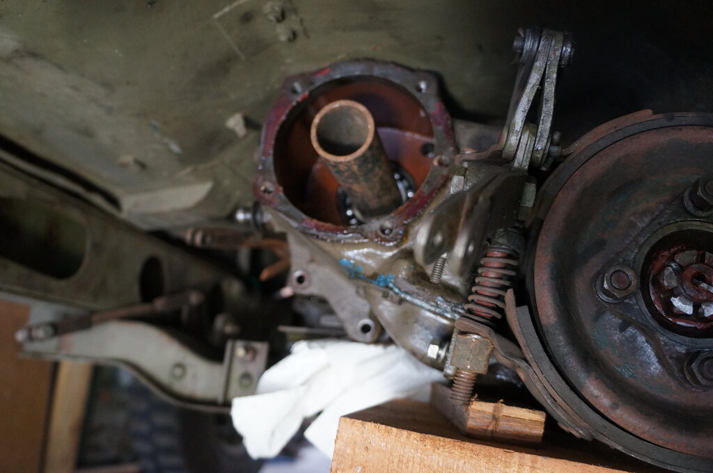
Transfer case. Note channel at top for interlocking pin. It may
need to be deepened slightly.
Installation:
Installation is largely a reversal of the above.
1. Check the interlock pin slides freely
in the channel in the transfer case. Place a square steel object against
it and see it slides freely. Chances are the channel is not deep enough,
and relies on the gasket thickness, which is unreliable.
Use a die grinder (e.g. in a Dremel) to
deepen the channel slightly to ensure free movement.
2. Clean surfaces for gasket. Ensure both are smooth and flat, otherwise bearing misalignment could occur.
3. Apply gasket to transmission first, using the bolts to position it. Remove bolts.
4. Bring the transfer case up on the jack until close enough to get a few turns in the left side bolts.
5. Put interlock pin in position, held by a thin magnet. Note that just resting on the bearing is too far down. Because of how the shift rails are designed, it is not possible to simply put the pin in the channel first. It has to come in from an angle.
6. Gradually bring the transfer case in, adding the other bolts.
7. Once the transfer case is re-attached, the wire securing the mainshaft in the transmission can be safely removed.
8. Remaining parts can be all replaced - order is not critical. I found that for the mainshaft nut to line up for the split pin, the torque had to be 125 ft. lbs.
9. Remember to refill the gearbox and transfer case!