Knowing of my interest in vibrator powered
radios, an acquaintance in the HRSA provided me with this set. What is
particularly unusual is that it is for 12V operation. I know nothing of
the set's history, except that my friend had found it at a market.
To give a clearer background to this type
of set, it is first necessary to talk about lighting plants, and the radios
that worked from them. To set the scene, let's go back to 1948 when this
set was produced.
The most common type of domestic radio
in Australia, was of course designed to operate from the AC power mains.
Some country towns, and central business districts of capital cities, instead
had DC mains. In both cases the voltage was typically 210-250V. For further
details about mains supplies, see
this article.
Away from cities and towns there was usually
no mains supply. Small villages and isolated properties away from the reticulation
system were on their own as far as electricity supply was concerned. In
these locations, battery sets were common. These came in a few different
types; the all dry battery set using 1.4V heater valves, with a 90V high
tension. Older sets would use a 2V lead acid accumulator with 2V heater
valves, but still a dry battery HT supply. The all dry battery set was
popular where no facilities existed to charge batteries.
By the late 30's, another type of set
became popular. It used a single 6V accumulator, of the type used in a
car, which provided heater current for the 1.4V or 2V heater valves, and
high tension by a vibrator power supply. It eliminated the need for the
expensive (and non-rechargeable) high tension battery. However, using such
a set did require access to charging facilities. This might be a trip to
the garage in the nearest town every couple of months, or the battery could
be alternated with that in the car (if you had one!).
[Before anyone points out such things
as air cells and rechargeable HT batteries - yes they did exist, but were
not common]
Home Lighting Plants.
Those without reticulated power mains,
and who could afford it, had their own DC supply provided by a "home lighting
plant". This was typically a single cylinder engine driving a generator,
which powered the house electrical system. If batteries were included,
the generator would only have to be run when the batteries required charging.
Otherwise, every time an appliance or light was used, the generator had
to be started. In fact, some systems did allow for remote or automatic
starting.
Other systems used a wind generator. For
these, batteries are obviously essential.
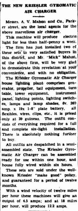
Description of a wind powered 6V lighting plant from 1937.
Home lighting plants appear to have had their origins in the U.S. with a Delco designed 32V system in the 1920's. By and large, 32V systems were the most popular in Australia, but smaller ones operated at 6 or 12V. Larger systems operated at 50 or 110V. Many domestic appliances were available in these voltages; particularly 32V. The 6 and 12V systems were only practical for lighting, radio, and other low power appliances such as a fan. For 32V and above, heating appliances such as irons and toasters become practical.
From this, we can see there was a market
for radios operating from home lighting plants. The 6V systems suited the
charging of batteries for existing 6V vibrator sets. While one might think
of simply using a 6V car radio, this draws about five times the current
of a domestic vibrator set.
The result was sets made for 12, 32, 50,
and 110V DC. For 6 and 12V sets, a vibrator or genemotor must be used to
obtain B+. In the case of 32V sets, this voltage is sufficient to use directly
as B+, where high power output is not required. However, many 32V sets
did use a vibrator. The only circuit diagrams I've found for 50V sets show
the use of 50V as the B+ without a vibrator. 110V sets obviously follow
U.S. design, using the 110V as B+.
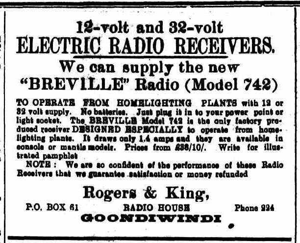
The Breville 12V Home Lighting Plant.
The Breville 742 is the first 12V domestic
radio I have seen. I am not aware of any other manufacturer making sets
for 12V lighting plants. It appears that Breville was supplying 12V lighting
plants, and then designed a radio to suit.
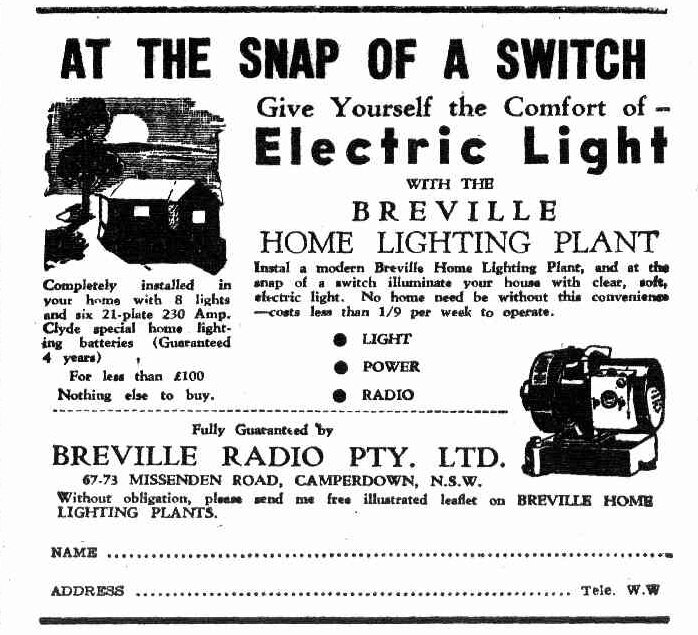
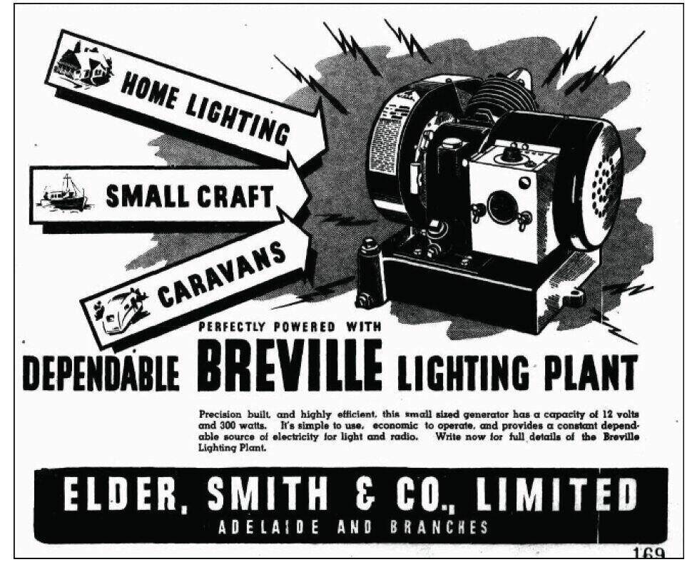
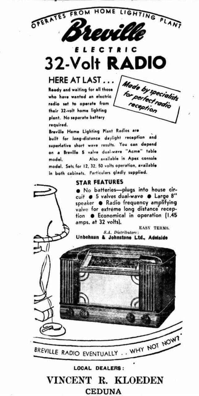
1949 advertisements for Breville's 12V lighting plant.
The 12V Breville home lighting plant had
an output of 300W. This allowed for eight 25W lamps. The battery supplied
was 230Ah, consisting of six two volt cells. The lamps were standard domestic
sized B22 based types, but with 12V filaments.
Readers of this site will know that I
have a 12V home lighting
plant for my own house; the difference being that it is solar powered.
Battery capacity is 300Ah. It can be seen why the 742 was such a desirable
addition to my collection.
I was advised by a very helpful reader
that the Breville generator was actually a rebadge of the U.S. made Johnson
"Iron Horse" which first appeared in 1936. A Canadian version, made by
the Outboard Marine & Manufacturing Co. was called the "Chore Horse".
There is some discussion about it on this
forum.
There is also a very detailed article
by Ray Robinson on his Tube Radio website about the Chore Horse https://www.tuberadio.com/robinson/museum/Chore_Horse/
These generators were used in WW2, and
it would appear that Breville bought them as a war surplus, subsequently
making a radio to work with them. The post war disposals advertisements
in Radio & Hobbies mention a 300W 12V generator, and more than likely
this was the same unit.
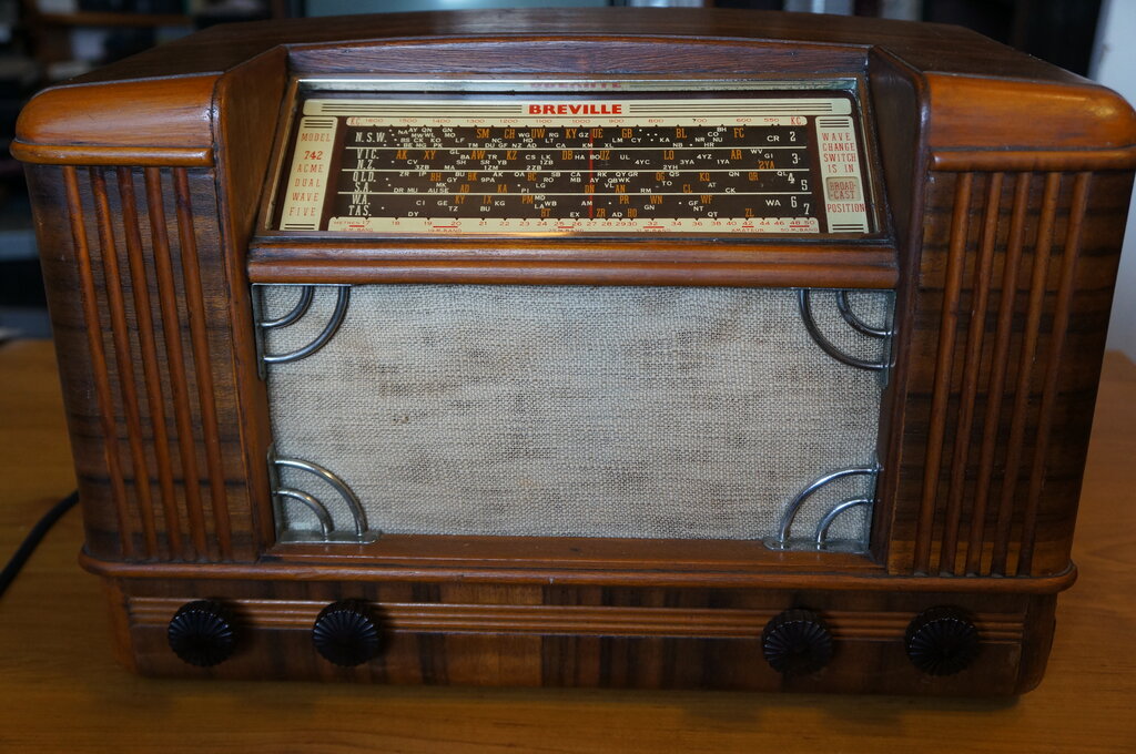
The Breville 742.
The 742 is a five valve dual wave superhet,
which was available in two forms, a console 742-C "Apex", and the 742-T
"Acme" mantel set. It was available in 12, 32, and supposedly 50V. The
set which came into my possession was the 742-T "Acme".
The set is housed in a large wooden mantel
cabinet with an 8" speaker.
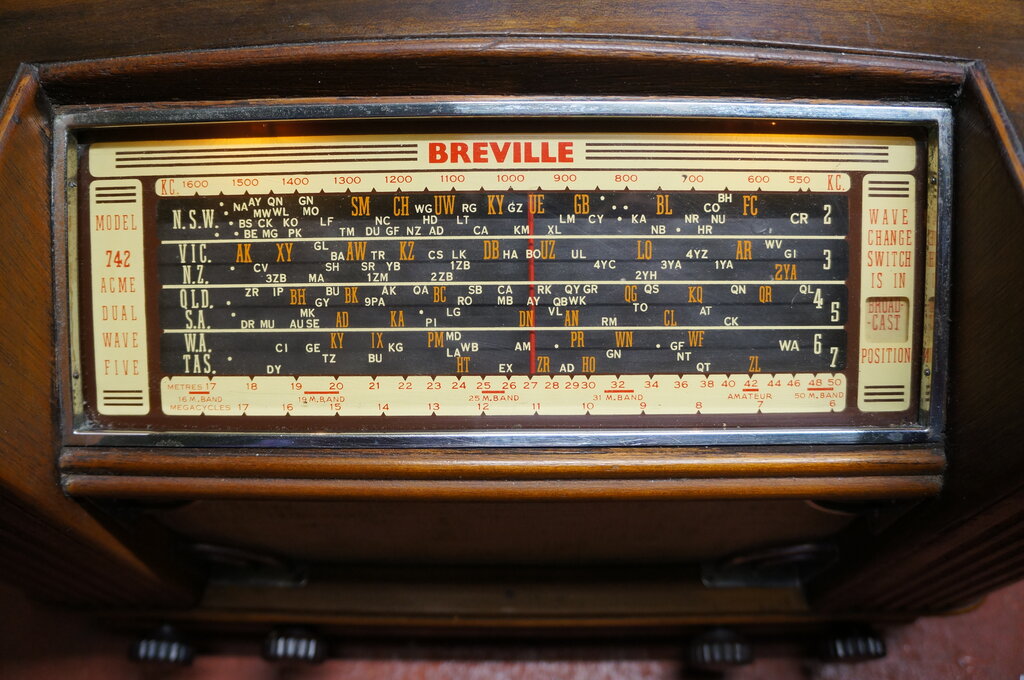
Model 742 Acme.
The appearance of the set was familiar,
since I had restored a 730 back in the late 1990's, which is the AC mains
version, and uses the same cabinet. However, the 730 does not have an RF
amplifier. There is also a 743, which is the AC/DC mains version of the
730.
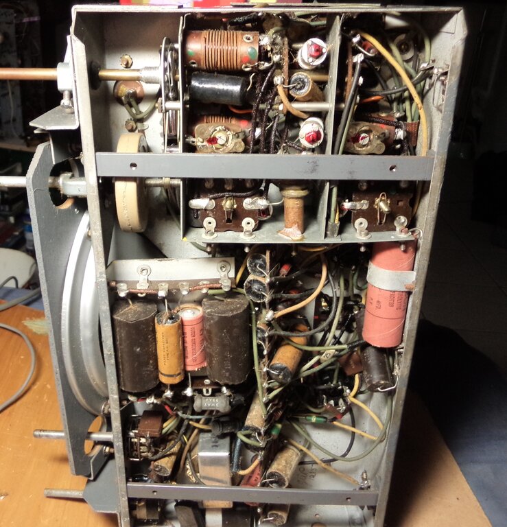
As received, the set had been a little bit 'got at', with the chassis to cabinet screws missing, along with the screws securing the vibrator power supply to the chassis. The dial lamps were missing, and a momentary push button switch had been installed in the side of the cabinet, to allow the dial lamps to operate only when required, thus saving on battery drain. However, this does not appear on the circuit, and the installation does not look original. In practice, an extra 250mA or thereabouts will have minimum effect on a 230Ah battery.
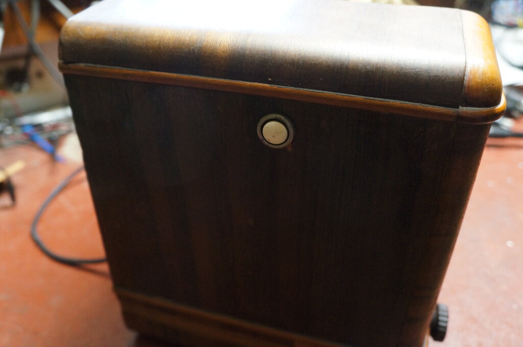
Switch added for dial lamps.
In original condition.
The Circuit.
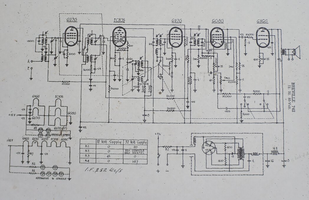
Despite "50-Volt" in the title, there is no such circuit.
For the most part, the circuit is conventional.
Incoming signal is amplified by the TRF stage using a 6U7. This is converted
to the IF of 262Kc/s by an ECH35. IF amplification is by another 6U7, and
detection and first audio is a 6G8. Audio output is a 6V6.
Note that in the SW position, the IF gain
is increased by shorting out the 2K cathode resistor of the 6U7 IF amplifier,
so that the cathode resistance is only 1K. For MW, the total cathode resistance
is 3K.
An interesting thing is the 25pF coupling
capacitor from the IF amp plate to the AVC rectifier. In most sets this
is 100pF. As a result, the AVC voltage produced is not as high, especially
with the higher reactance of 25pF at 252Kc/s.
252Kc/s IF.
The 252Kc/s IF may appear unusual, but
it was used in some car radios, and at least one other Breville set, the
portable 857. The lower IF provides a higher gain and better selectivity.
However, a preselector or TRF stage is required to improve the image rejection.
Because the difference between the local
oscillator and RF input frequencies is a lot less at 252Kc/s than at 455Kc/s,
it is more difficult to filter out the image response with just one tuned
circuit in the aerial input.
Consider a station on 900Kc/s. For an
IF of 252Kc/s, the local oscillator operates at 1152Kc/s. Now, in addition
to the input responding to 900Kc/s, it will also respond to 1152 + 252
= 1404Kc/s. With a single aerial coil, loaded down by a long aerial,
the selectivity will be insufficient to prevent signal from a strong station
around 1404Kc/s entering the input of the converter valve, and interfering
with reception of the desired station at 900Kc/s. Anyone who has used a
crystal set in a strong signal area with multiple stations, will be familiar
with the limitations of a single tuned circuit.
If the IF is increased to 455Kc/s, the
local oscillator is now 1355Kc/s. The image response will therefore be
1355 + 455 = 1810Kc/s. Not only are there no broadcast stations at this
frequency, but 1810Kc/s is much further away from 900Kc/s than 1424Kc/s.
A single tuned circuit now has a better chance of rejecting the image frequency.
Tone Control.
As with all good quality radios using
a pentode or beam tetrode output valve, negative feedback is included.
In the 742, the frequency response of the feedback network is adjustable
by means of a three position rotary switch, which functions as a tone control.
The feedback network is fed from the 6V6 plate via a 0.5uF condenser.
In the mid position, the negative feedback
is not frequency selective, giving a flat response. Voltage from the 6V6
plate is fed via the 0.5uF, and 15K and 20K resistors into the 40R to earth.
The voltage divider (35K + 40R) introduces the feedback into the 6G8 cathode.
In the high position, the junction of
the 20K and 15K is partially shunted to earth by a 0.02uF in series with
a 5K. As the frequency rises, the reactance of the 0.02uF decreases, shunting
more of the signal to earth. Thus, the 6G8 receives less negative feedback
at high frequencies, and more feedback at low frequencies. With the gain
of the audio system reduced at low frequencies, the result is more treble
response.
In the low position, a 0.003uF is connected
across the 20K + 15K. As frequency rises, the feedback increases, and gain
rolls off. The result is more bass response.
Additional to the tone control is an extra
winding on the first IF transformer. The tone control also controls the
selectivity of this transformer. Without opening and examining the transformer,
it appears the coupling is altered, giving a narrower or broader response.
This is also tied in with the MW/SW switching.
Presumably, the response is wider when MW is selected to give good fidelity.
For SW, where selectivity and gain is more important, the response would
be narrower.
Pick Up Terminals.
Pick up terminals are provided, but are
not shown on the circuit. Connection is between earth and the junction
of the 0.1uF, 50K and 500K resistors in the detector load circuit. Looking
carefully at the circuit, you can see where I've pencilled it in. This
type of connection is more of a sales gimmick than anything else. There
is no way to select between radio and gramophone, except by tuning off
station. There is some DC present at the terminals from the detector. Assuming
a magnetic pickup, which would have been common in 1948, this DC would
be largely shunted to earth. This would be avoided if the input was on
the other side of the 0.1uF; i.e. across the volume control pot.
Power Supply.
Despite being advertised for 12, 32, and
50V (and designated as such on the circuit diagram), there seems to be
no circuit for the 50V version. It is possible this never actually existed,
since outside of the telephone system, 50V lighting plants were much less
common. In fact, no Breville circuits for 50V were found in the Australian
Official Radio Service Manual. Just what design the 50V version would use
(if it existed) is unclear. 50V is high enough not to require a vibrator
power supply. The vibrator power supply as shown for the 742, used with
a dropping resistor for 32V, is not suitable for 50V.
A very faint possibility is the fictitious
50V set was just the 32V design with a resistor in series with the whole
set.
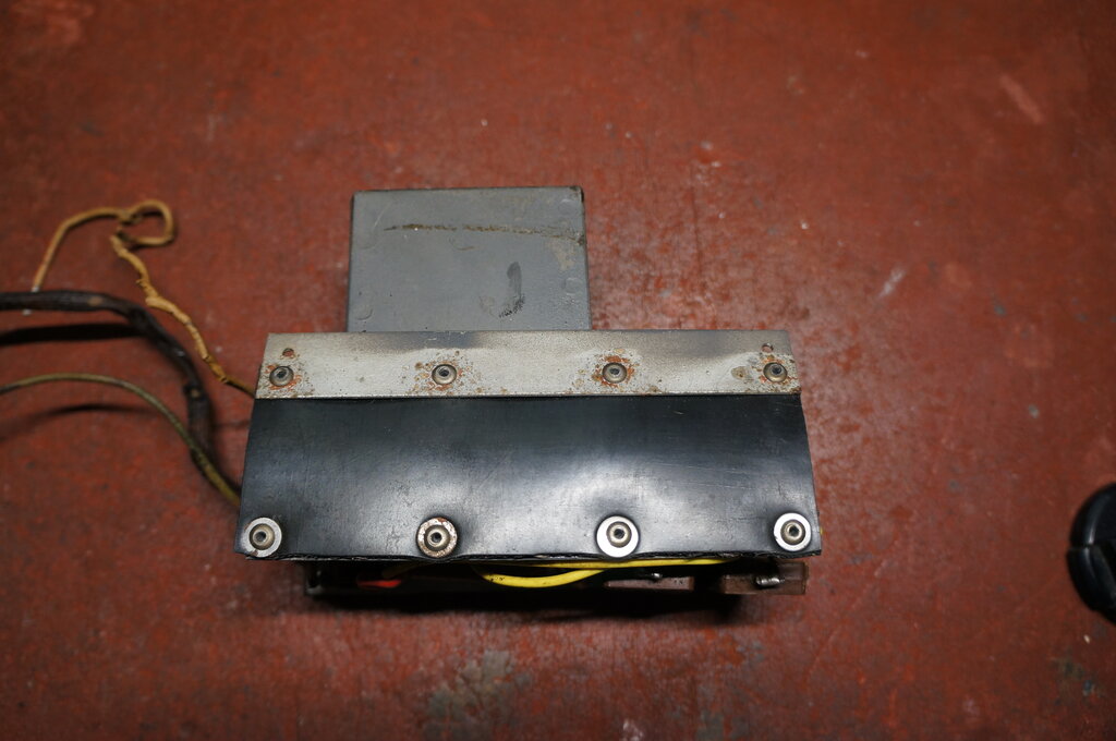
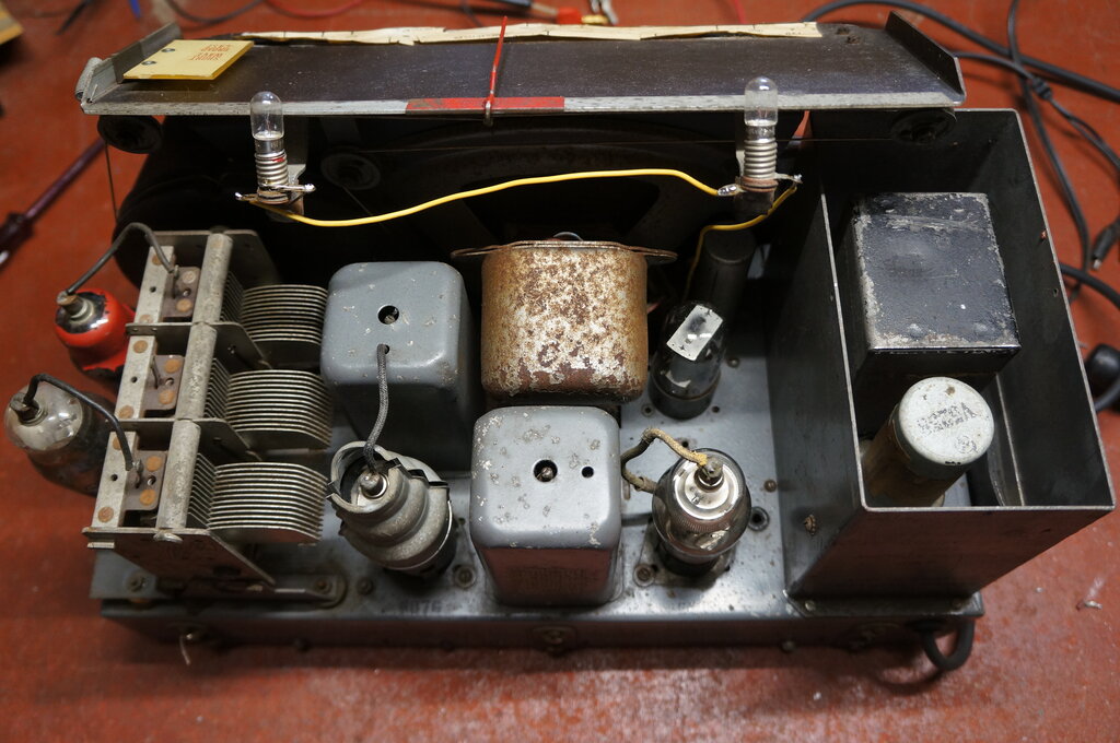
Looking at the 12V version first, the power
supply is conventional, using an Oak
V5258 12V synchronous vibrator. Breville have attached a label to the
vibrator, designating it as Breville No.4. This is interesting since the
V5258 is a standard type. It's possible Breville labelled it with their
own number to avoid the confusion of a 12V vibrator being used in a 32V
set.
The two dial lamps are 6.3V types, connected
in series across the 12V supply. The console version of the set has four
dial lamps, which are connected in two separate strings. Valve heaters
are connected in two series parallel branches. The ECH35, 6U7 and 6G8 heater
current adds up to 900mA for one branch. The 6V6 and remaining 6U7 draw
750mA, so a 45R resistor (R3) is added to bring this up to 900mA for the
other branch.
The 32V version uses the same 12V vibrator
power supply, but with a 20R resistor in series (R1). Assuming the power
supply draws 1A, this will drop 20V, allowing it to work from 32V.
However, this is an undesirable design,
because when the set is first switched on and the valves have not warmed
up, the B+ current is minimal. Thus, the input to the power supply will
be more than 12V. Apart from the timing capacitor not being the correct
value for this higher voltage, there is the danger of contact arcing in
the vibrator, along with stressed transformer and timing capacitor insulation.
A better scheme is to use a 32V vibrator transformer, but with a resistor
for the vibrator driving coil only. It was not until a few years
later that Oak vibrators became available in 24V and then 32V.
For 32V, all the dial lamps are in series
with an appropriate resistor (R2), depending on whether there are two or
four lamps. The valve heaters are all in series, but with all the 300mA
heaters in one group shunted with a 167R resistor (R4). This brings the
current up to 450mA so that the 6V6 can then be connected in series.
No fuse is provided, which is poor design. Should there be a short circuit or overload on the B+ supply, the vibrator and transformer are likely to be damaged. If the vibrator contacts weld together as a result, there will effectively be a short across the 12V supply.
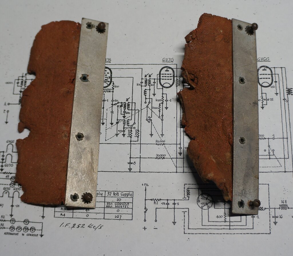
Rubber support strips were no longer usable.
I had some neoprene which was just the right thickness, and made a perfect replacement for the rubber. This was riveted to the chassis and the steel strips which attach to the box.
Neoprene replacement for the rubber strips.
The foam rubber supporting the vibrator
socket was in reasonable condition, but had deformed from years of the
vibrator's weight upon it. Simply removing it and mounting it upside down
was sufficient to give many more years out of it. Next was the electrical
restoration.
Applying 12V to the power supply produced
results straight away, which just goes to show the reliability of Oak vibrators.
The voltage was a bit low, at around 125V into a 240V 15W light bulb, but
bear in mind there is no filter capacitor in the supply itself. Also it
was quite possible the duty cycle of the vibrator had decreased.
The 400R primary damping resistors had
increased up to around 500R, so were replaced with 390R 1W. Since the 0.02uF
timing capacitors were mica, I decided to leave them. Had they been paper,
replacement would be essential.
The B+ RFC was open circuit, due to careless
replacement of the 0.1uF RF filter. The fine Litz wire had been damaged
near the solder tag of the choke. This was easily repaired.
The capacitor shown as 0.5uF from the
transformer primary centre tap to earth was an electrolytic of unknown
value (the paper label was damaged), and it did not look original. It measured
O/C, so replaced it with a 0.56uF polyester type.
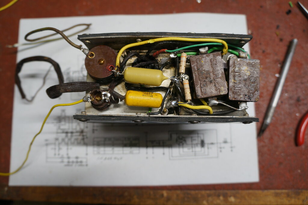
New capacitors and damping resistors. B+ RFC is at bottom left.
Additionally, the rubber wiring needed
replacement since it had gone brittle and was cracking. Particularly for
the connections to a floating vibrator socket, the wire should be very
flexible to reduce transmission of vibration to the chassis.
Next to restore was the vibrator itself.
While it was working, I could hear bits of brittle rubber rattling around
inside it, and the contacts were in need of cleaning and adjustment.
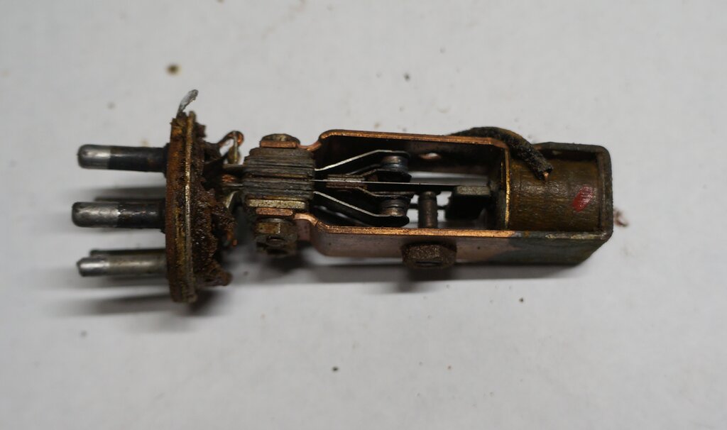
Stack support rotted away.
The base was removed and cleaned up. To
replace the rubber, I made two discs of adhesive foam rubber which is about
the right thickness. Then, a third disc is made up, but with a U section
cut out to slide over the bottom of the stack, and to cover the solder
tags.
The rubber inside the can at the top also
needed replacement. A felt disc was cut out for the top, and a strip of
the adhesive foam rubber to line the side of the can. It's important that
the vibrator mechanism can float, so there needs to be a gap between it
and the foam rubber. In this regard, felt is used right at the top, rather
than foam, since foam is too thick and will press against the top of the
coil.
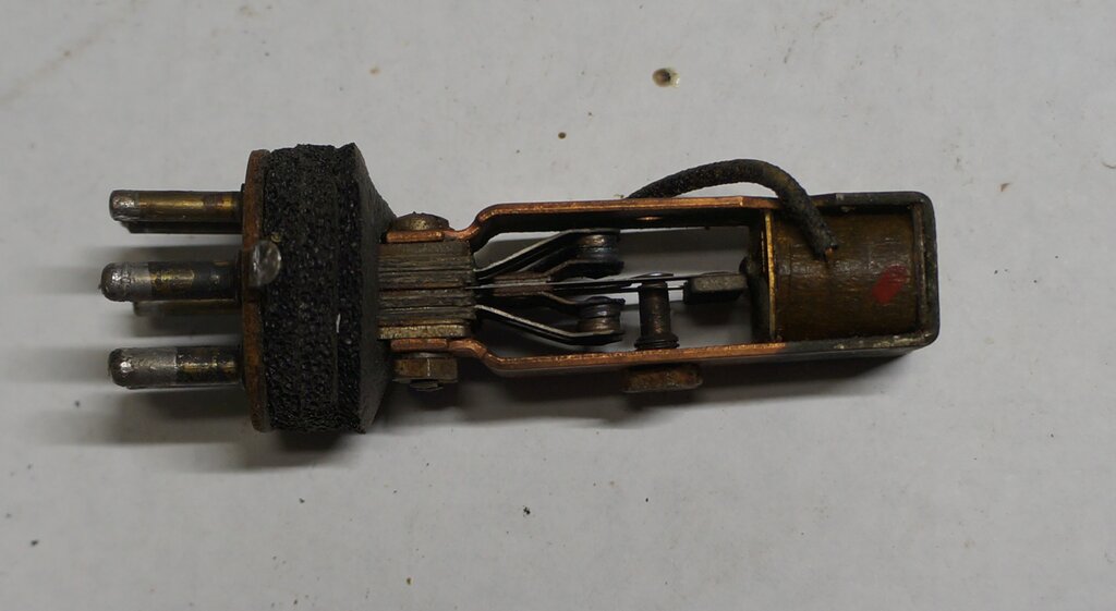
New foam to support stack and insulate connecting wires.
For checking the contacts, I used my vibrator test panel. The Oak vibrator has an 80% duty cycle, which for 100c/s, means a contact on time of 4ms. The secondary contacts need to be slightly less, at 3.8ms.
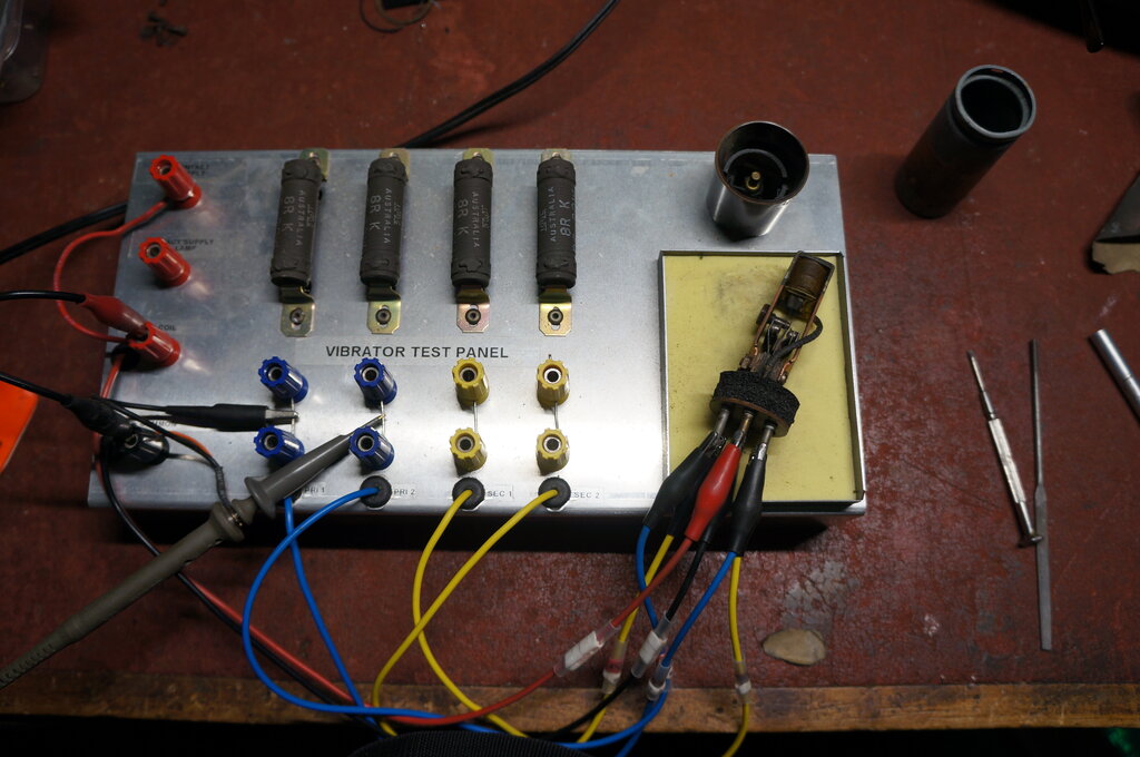
As suspected, the contacts needed to have
their duty cycle increased. The vibrator had been well used, and years
of hammering had spread the contacts. The jagged waveform indicated cleaning
was also needed, and I simply used a jeweller's file.
The result is not perfect, with a points
file being preferred. However, the thickness of the points file requires
the vibrator be disassembled. For a low power unit like this, it was quite
good enough.
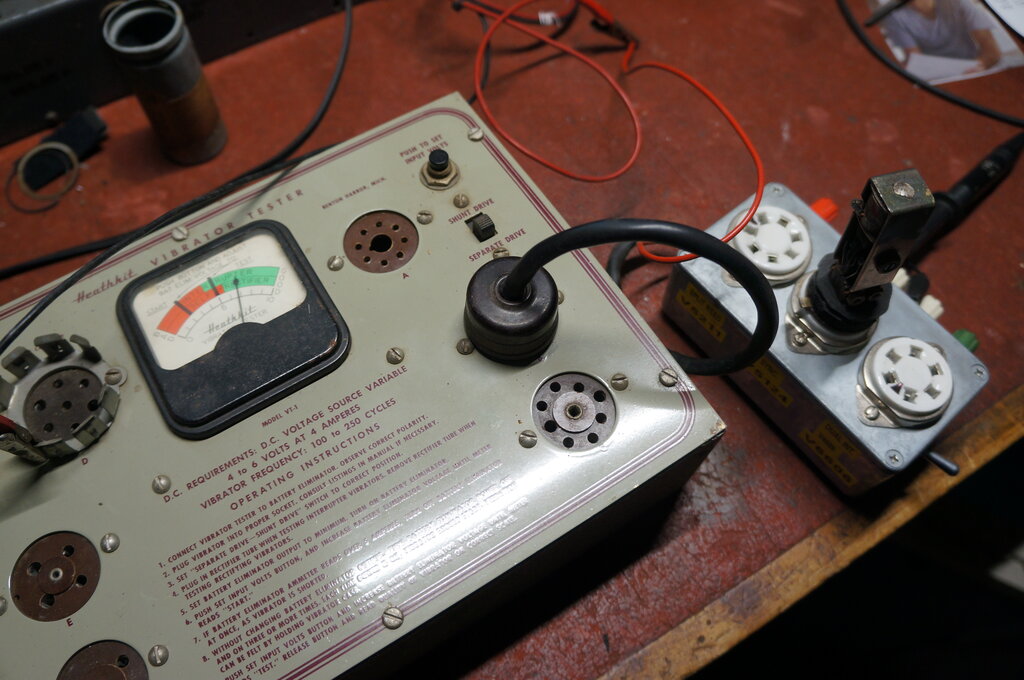
Heathkit
vibrator tester tests under normal operating conditions.
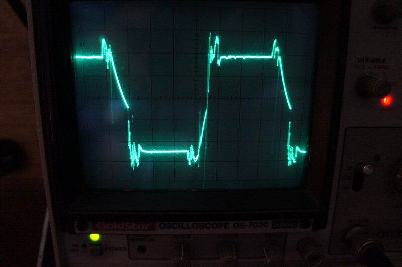
Primary waveform in the set. The peaks at the edges are due to this
being a synchronous vibrator. We can clearly see the secondary contacts
are closing after, and opening before the primary contacts, which is as
it should be.
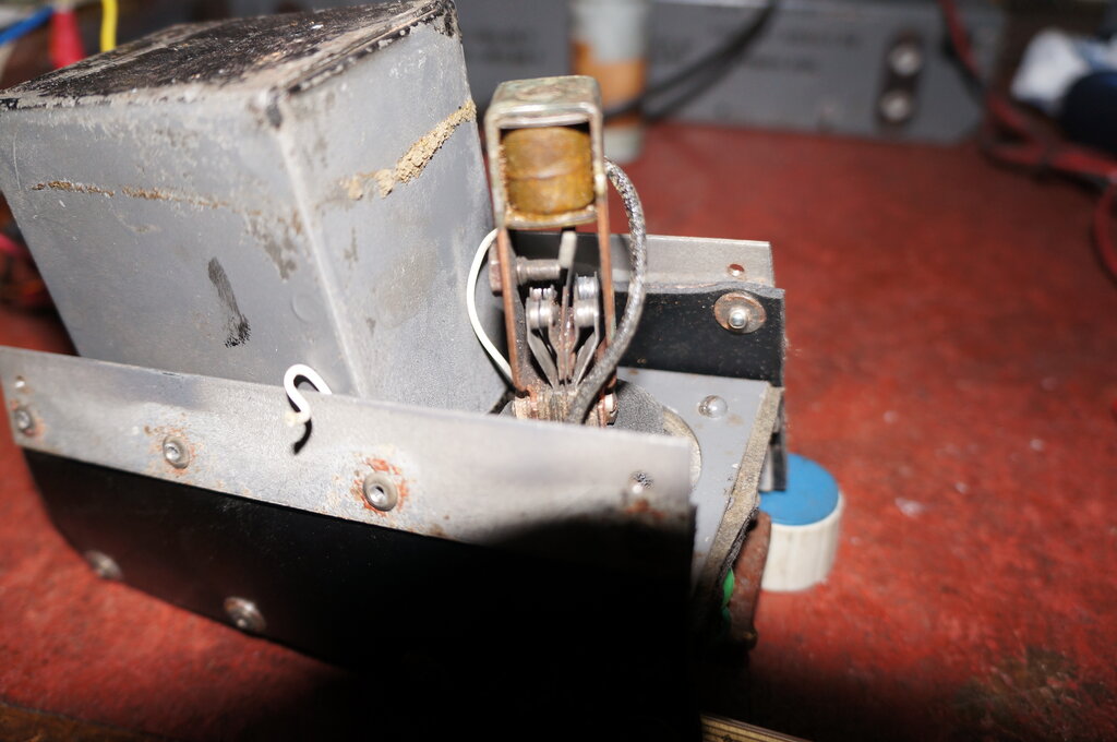
Final check to see no sparking at the contacts. Camera caught the
reed on on the pull swing.
With the vibrator supply restored, the B+ was up around 160V. While less than the usual 250V the valves are rated for, the lower B+ means a substantial reduction in battery current. Additionally, the 6V6 is over biassed to further reduce B+ current. Audio output is still more than sufficient for a domestic radio.
The supply was reinstalled on the radio
chassis,
reconnected and powered up. Of course, I'm aware of all the old capacitors
in situ, but I was keeping an eye on the current draw. As it happened,
there was nothing apart from the buzz of the vibrator and presence of B+.
In fact, the current draw was no more
than when I was testing the supply with no load.
Blown Valves.
And here we come to a very sad fact about
radios designed for low voltage lighting plants. Most surviving examples
have been plugged into 240V out of ignorance. The thought that a radio
might operate at something besides 240V escapes the typical person, curious
to see if the radio works. Battery and 4 or 6V vibrator sets have a better
chance, since crocodile clips or battery plugs with multiple wires, force
the curious person to think otherwise. Nevertheless, there is a danger
with 6V vibrator sets being connected to a 12V car battery. Fortunately,
both my 6V vibrator sets weren't damaged thus, but my 32V "Standard" wasn't
so lucky.
Sets for home lighting plants are fitted
with the same kind of two core cable as one uses with 240V appliances,
and in most instances, a three pin 240V plug was also fitted. While many
sets are labelled as to their voltage, this is conveniently ignored, and
the presence of a three pin plug entices the ignorant to apply 240V.
The end result is a blown set of valves
and dial lamps. If you want to restore sets for lighting plants, expect
to replace lots of valves!
The Breville was no exception, with all
valves but one of the 6U7's blown open circuit. How the vibrator survived,
I do not know. I can only assume a fast responding circuit breaker. Incidentally,
this is another good reason to include a fuse inside the set.
Interestingly, there was an EBF39 in the
ECH35 socket. Had it not been damaged, it could have been used to replace
the 6G8.
Anyway, a look through my valve collection
provided replacements for the 6U7, ECH35, 6G8, and 6V6.
At this point, all valves lit up, but there
was still no audio. The 6V6 grid was responsive, but not the 6G8. No voltage
was present at the 6G8 cathode pin, and its plate voltage was almost the
full B+. Obviously, the 6G8 wasn't drawing current, despite screen and
plate voltage.
I tried another 6G8 and the set came to
life. Not surprisingly, the 6V6 grid was positive, so first thing was to
replace the grid coupler (0.01uF), so as not to ruin the valve, and also
to reduce the B+ current, allowing a bit more voltage from the power supply.
The 6G8 I previously tried responded to
a resolder of the cathode pin, and went back in. How many perfectly good
bakelite base valves have been thrown out because of a dry jointed pin?
With the set basically working, now was the time to go through and re-cap and re-resistor it. The only paper capacitors left were those across the 12V supply, and cathode bypasses. The B+ electrolytics were all OK and left, but the audio bypasses were open circuit. Replacing them brought the gain up by a useful amount. The only tricky part of this was replacing capacitors around the front end coils and the wavechange switch, but with care and dexterity was completed without too much of a challenge. Aside from the 6G8 plate resistor, the rest were close enough and not replaced.
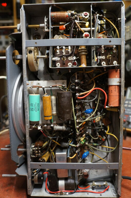
Under chassis complete. Note fuse at bottom right.
The lack of valve shielding did not appear
problematic. The 6G8 and one of the 6U7's are missing their Goat shields,
and the ECH35 has lost a lot of its metallic paint used for the same purpose.
There's no sign of instability, so have not worried about it.
Final under chassis work was to replace
the power cable with polarised plug, and install a 5A fuse. For the power
cable, I used Jaycar WB-1754. This is a two core cable with black and red
conductors, and a black outer sheath. One could install a zener diode after
the fuse to protect against the application of 240V. It must be noted that
the 12V supply needs to be polarised correctly because of the synchronous
vibrator. If input polarity is reversed, so is B+ output polarity. While
the valves are not harmed by this, the electrolytic capacitors will draw
excess current and may break down.
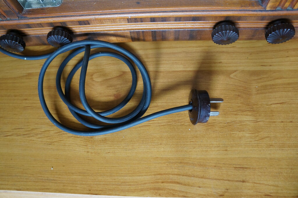
Polarised plug for use on 12V.
Dial Lamps.
The 742 was run for several days with
complete reliability. The final thing was to deal with the missing dial
lamps. There are two steel strips spot welded to the back of the dial,
which looked like they were made for the ubiquitous push on E10 lamp socket
used on most Australian radios. It quickly became apparent that they weren't
meant to be used this way, with the length and position being quite unsuitable.
It's been many years since I restored the 730 and could not remember its
dial lamp set up. Luckily, the 730 was described in Silicon Chip, and from
what I could see of the photos, the dial lamps were actually in a kind
of reflector sub assembly, which pushed onto the two metal strips. Fabricating
such a thing is well within my capabilities, but the question was how to
attach it to the metal strips. This wasn't clear in the photos, and it
did look like they had used the spring clip in the light sockets. But,
for the kind of sockets I had this wasn't going to work.
Did we really need the reflector? Testing
a 6.3V bulb at the top of the dial with the chassis in the cabinet worked
perfectly with good even dial illumination. The simple way out of the problem
was to shorten the metal strips, and bend them 90 degrees. The bulbs would
then be just at the top of the dial. I used 250mA dial lamps.
Dial lamps mounted at the top of the dial.
The result was completely successful.
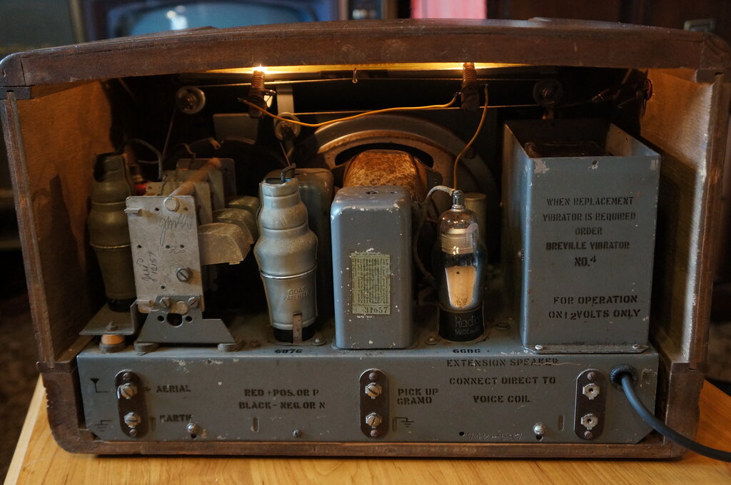
Chassis back in cabinet. "When replacement vibrator is required..."
- that's a bit pessimistic. On the contrary, this set has the original
vibrator in good condition, and it's been well used.
The screws and washers to secure the chassis
in the cabinet were missing, as were the back screws on the chassis securing
rails. I could have retapped them to take 4mm screws, but I found some
of the correct thread. I would have assumed they were a BA or Whitworth
thread, but could not match them to anything I had.
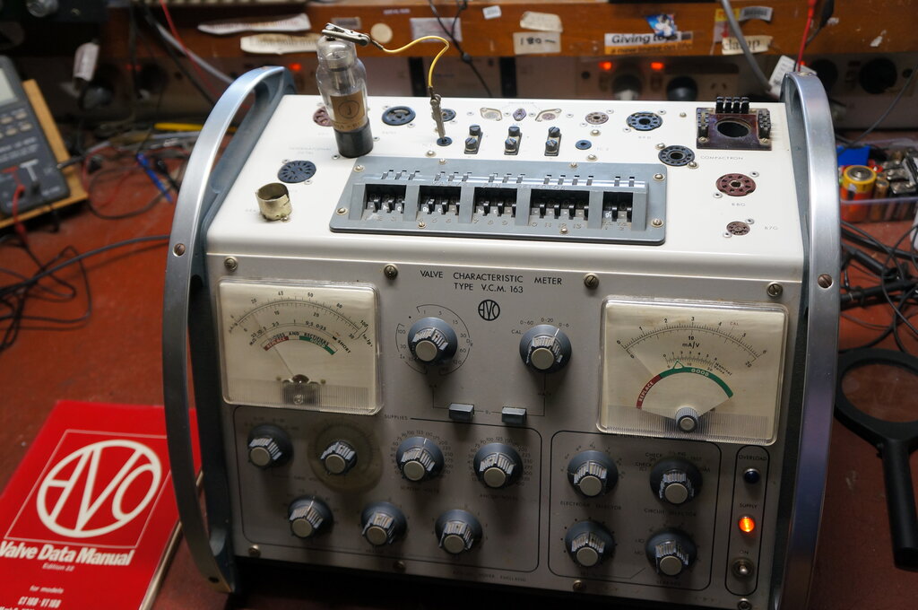
Testing the 6U7.
Increasing the heater to 9.3V did bring
up emission and transconductance to a reasonable level. It would appear
that this 6U7 was just very worn out, or had perhaps been damaged from
the excess heater voltage that burned out all the other valves. In view
of the
much higher gain, I replaced the shield
on the replacement 6U7.
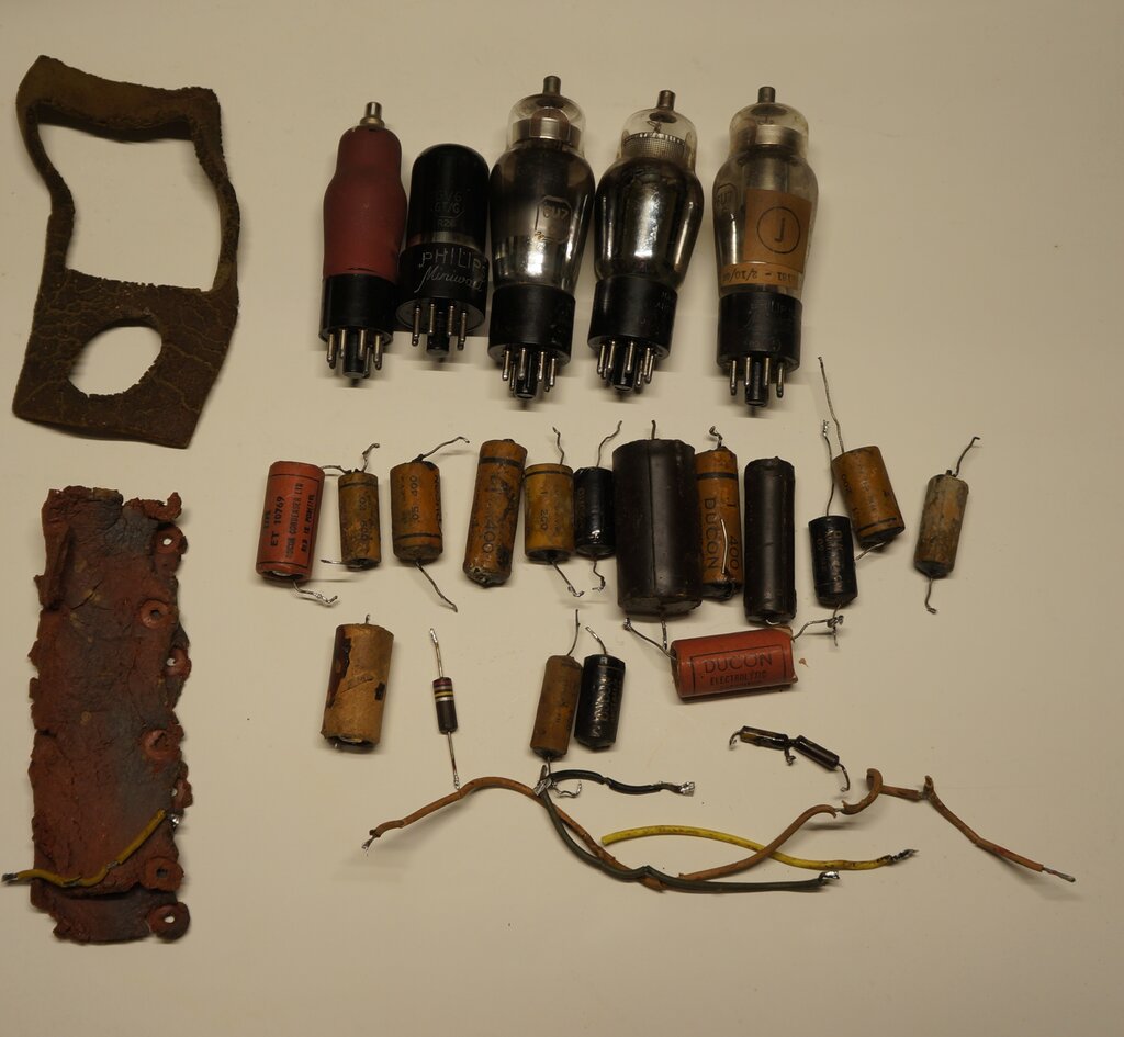
Dead parts from the 742.
Sound quality is excellent, as would be
expected from a baffled 8" speaker, and an audio amplifier with feedback.
There is no vibrator interference, but the negative side of the 12V supply
needs to be earthed.
Current draw at 12V is 2.1A.
More Faults.
For the testing, I had been listening
to the mid and low end of the MW band. Out of curiousity, when I tuned
to the high frequency end of the band, the sensitivity suddenly disappeared
around 1350Kc/s. It wasn't the common fault of shorting tuning condenser
plates, since the drop off was not sudden. It was obviously the local oscillator
dropping out. On short wave, I discovered the same thing, except the gang
didn't have to be opened quite as much for the oscillator to drop out.
What could cause this? There's not a lot
of components in the local oscillator circuit; the grid leak components,
the coil, and the tuning and trimmer condensers. My initial thought was
the grid condenser could be faulty, since I have had that before. Alas,
even at 500V it tested perfect. Nevertheless, I temporarily installed a
parallel pair of 33pF ceramic capacitors instead. The fault was the same.
The resistors were all OK. I even tried putting the full B+ on the oscillator
supply, but the improvement was only minor.
Despite the good gain of the hexode section
of the ECH35, maybe the triode was faulty. I had a 6J8 conveniently to
hand, so plugged that in. Up came the local oscillator - and right across
the band this time. Not only that, it was working across the short wave
band as well.
Sure enough, testing the ECH35 revealed
a good hexode section, but the triode was very weak. Yet another ECH35
was taken from my collection, and this time it worked as it should.
With complete band coverage, the set seemed to be working well. That is, until the volume was turned right up. I could hear instability or oscillation in the audio. Maybe the 6G8 really did need shielding. I tried that, but no difference. Another possibilty is one of the B+ electrolytics was faulty. That was the next thing I tested. There was a few volts of audio ripple on the B+ supply, which disappeared when another capacitor was bridged across it. Not only that, bridging the supply with the extra capacitor stopped the instability and brought a further improvement in the audio quality, particularly with the bass response. The 16uF second filter capacitor (shown as 8uF in the circuit) was therefore replaced, fixing that fault.
All during the restoration and testing, the IF amplifier 6U7 would intermittently stop working. This is the valve I resoldered the cathode pin on. Tapping on the side would restore reception for a time, but it would always fail again. Next, I tried resoldering all the base pins, but there was no improvement. I could only conclude there was an internal break in one of the connections inside the valve. Replacing it finally fixed it. I used a VR100 since I have more of them than 6U7's, and one happened to be in the first valve box I looked in.