With my other vibrator equipment, it was
only natural that a commercially made vibrator tester should be added to
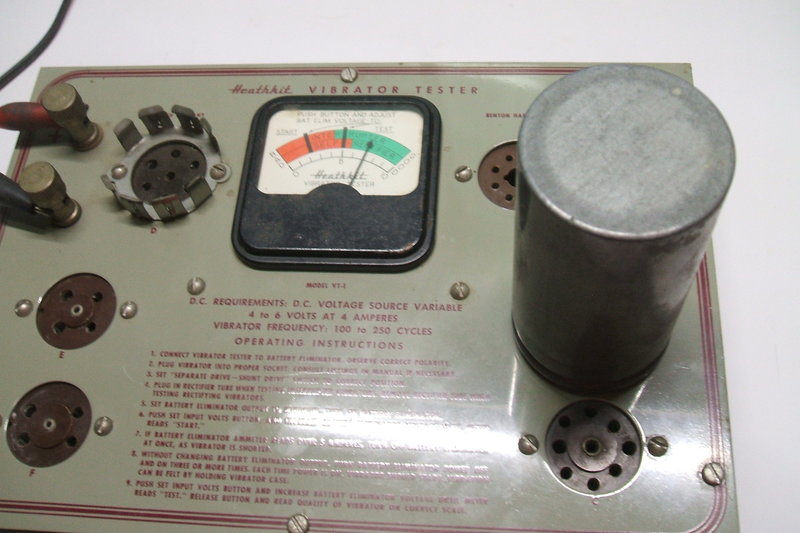
the collection. The Heathkit VT-1 appeared in 1953 in the U.S. and was
a popular piece of test equipment.
I already have built a vibrator tester
as described here.
It operates on very different principles and requires a CRO to observe
the vibrator condition. My design allows one to check:
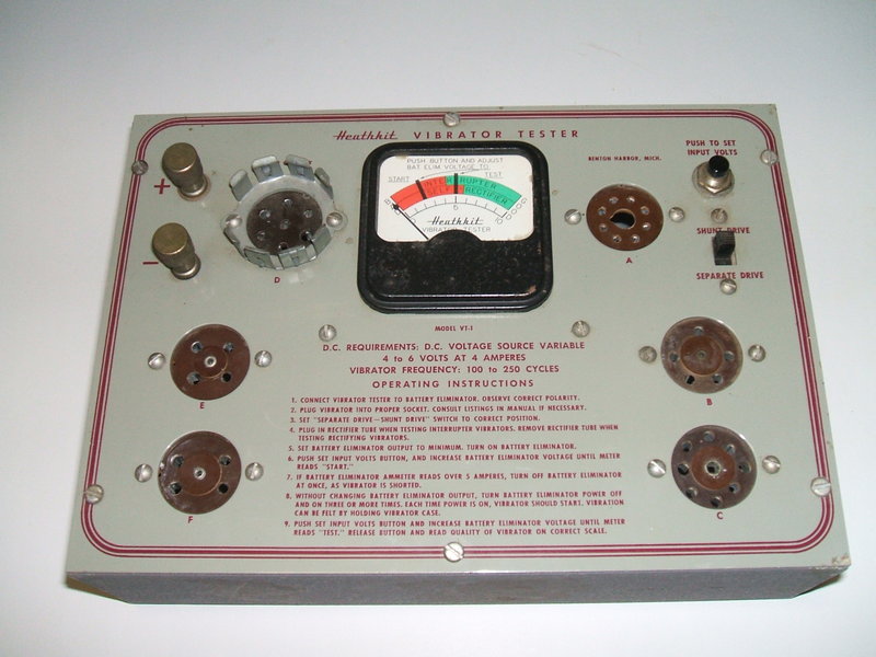
The VT-1 requires an external DC power
supply; variable from about 4V to 6V, and with a current capacity of about
4A. Heathkit recommend using a battery eliminator of the type used for
testing car radios, and not surprisingly, such a unit (BE-4) is part of
the Heathkit inventory.
The vibrator under test is plugged into
the appropriate socket, and the "shunt drive - separate drive" switch is
set appropriately depending on vibrator type. For example, Oak types have
a separate contact for the driving coil, whereas most Mallory types are
shunt drive, with the driving coil connected across one set of switching
contacts.
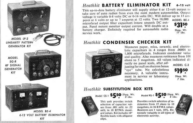
The BE-4 was recommended for the power supply to operate the tester.
If the vibrator is non synchronous (otherwise known as an "interrupter" type), a rectifier valve must be plugged into the octal socket. The valve socket is wired to take a 6X5 or 0Z4. If the vibrator is synchronous ("self rectifying") the valve is not inserted.
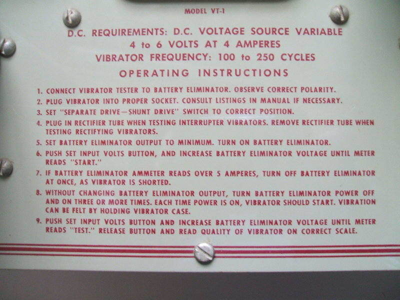
Now the vibrator can be tested. Push the
"Set input volts" button, and with the battery eliminator at minimum volts,
gradually increase the supply voltage to the "Start" line on the meter.
The vibrator should consistently start at this lower than normal voltage.
If it passes the start function, press
the "Set input volts" button again and increase the supply to the "Test"
line on the meter. The vibrator is now operating at normal supply voltage,
and the condition can be read off the meter scale.
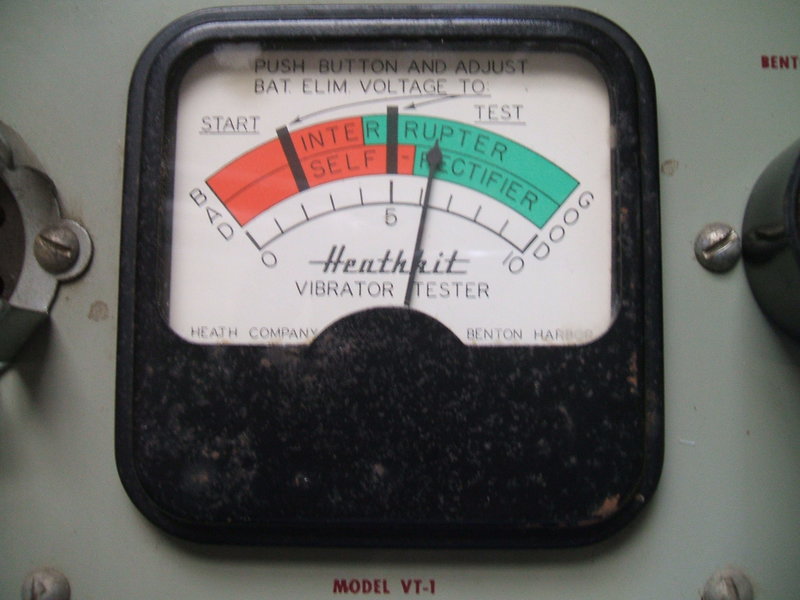
Two scales are provided because the output
voltage differs between synchronous and non synchronous types with a valve
rectifier. This is because there is a voltage drop across a valve rectifier,
whereas the contacts of a synchronous vibrator have no voltage drop.
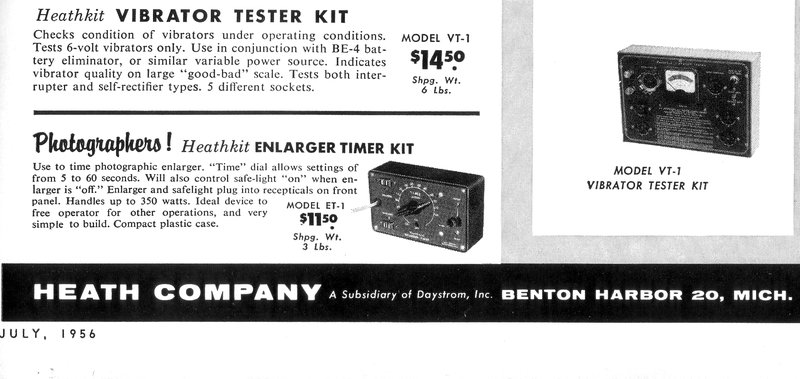
By mid 1956, Heathkit acknowledged the 6V limitation of the VT-1.
Secondly, the range of vibrator sockets
does not include the UX-6 base used with many synchronous types, and the
UX-7 base used with split reed types.
In fact, despite the array of sockets,
there is only one Australian made vibrator that can be tested on this instrument
as wired; the Oak V5105 with UX-4 base. Provided sockets C and F
are rewired, the Ferrocart PM237 and PM104 can also be tested.. Again,
this is not meant to be a criticism, as the VT-1 was designed for the U.S.
The 3 pin Delco socket is not included as it was only used for 12V types.
Two Australian vibrators that can be tested; at left is the Oak
V5105, and at right is the Ferrocart PM237.
A limitation of testing non-synchronous vibrators is that the condition of the rectifier valve will also affect the meter reading. Therefore, if the output reading is low, the rectifier valve should be substituted with a known good one, before concluding the vibrator is weak. In this regard, the VT-1 can be used to also test the rectifier valve.
Another limitation is that the "one size fits all" meter scale does not accurately reflect the differences in duty cycles of different vibrator types.
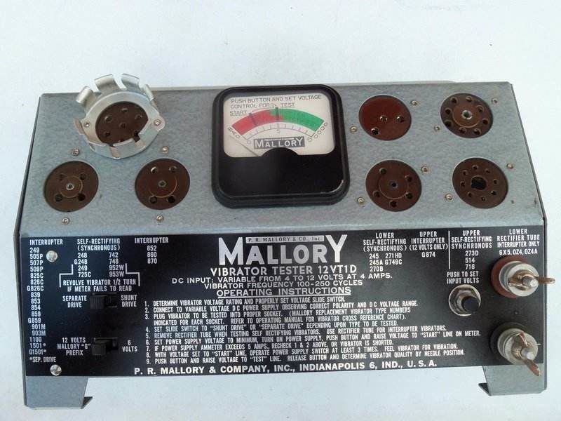
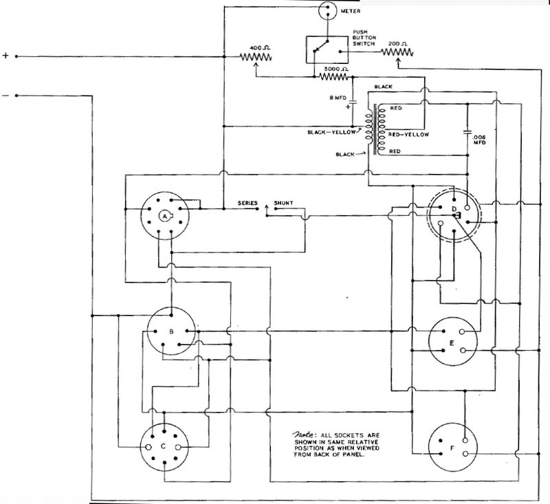
Mallory's 6VT1 tester circuit. At right is shown the Mallory 12VT1D
tester. Note how the Heathkit meter resembles that which Mallory have used.
The 12VT1D includes the 3 pin Delco socket.
The Heathkit VT-1. Note the similarity.
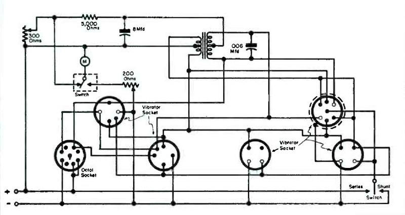
How the Tester works.
There are essentially three parts to the
circuit; 1) Metering, 2) Synchronous vibrator power supply, and, 3) Non-synchronous
vibrator power supply.
A number of different sockets are provided
which are:
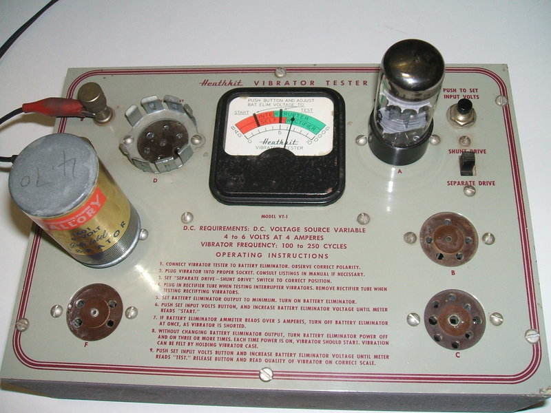
Mallory type 245A being tested in socket "B".
The "Shunt drive" / "Separate drive" switch is connected to sockets D and E. In the case of socket D, the centre pin is the reed connection for shunt drive types. For the Oak vibrators using this base, the centre pin is the driving coil, with the reed connection being the vibrator can. For this, and the 7 pin reversible variant of the shunt drive vibrator, which also uses the can as the reed connection, a grounding cup is provided for the socket. It connects to the chassis of the tester and the negative supply input. For more details on this reversible base, see here.
Testing a reversible synchronous vibrator (Mallory 725C). Note that
no rectifier valve is used.
For socket E, the switching is actually unnecessary, as the pin 4 is vacant on shunt drive types. Whether 6V is connected to this pin all the time or not makes no difference. In fact, many car radios have pin 4 connected even though they are designed with shunt drive types. It allows one to use a separate drive type as a replacement with no modification.
Socket C appears to be obscure.
Even with a reasonable collection of U.S. made vibrators, I do not have
any fitted with all eight pins. Looking through the vibrator catalogs
does not show any. However, it does take the Delco 5 pin base used by some
synchronous types. Interestingly, looking at the list of Mallory types
that plug into this socket, as seen in the previous photo of the 12VT1
tester, we see 273D, 514 and 716.
These all use the 5 pin base. At this
point it is doubtful that any vibrators were actually made with all eight
pins.
Mallory type 245C being tested in socket "C".
Socket F is for the Delco 4 pin
base. It is a UX-6 socket but with two of the pins (2 & 5) blanked
off.
A vibrator with the 4 pin Delco base will thus fit a UX-6 socket. In Australia,
this base suits the common Ferrocart PM237 and PM238 used in Astor car
radios. In fact, most of these radios did use a UX-6 socket.
However, because the AWA/MSP Oak equivalents
of the PM237 and PM238 have six pins (V4010 and V4016), they cannot be
tested in this socket.
1) Metering.
The meter displays the input voltage when
the push button switch is pressed. Current flows from the positive supply
input via the meter, the normally open switch contacts, and the 200 ohm
calibration pot, back to the negative supply. The meter is not actually
calibrated in volts, but simply as "Start" and "Test". "Test" is the normal
running voltage and is therefore 6.3V. When calibrated thus, "Start" shows
the input being 5V. The point of this is to determine how reliable the
starting of the vibrator is. With shunt drive types, any wear in the contacts
shows up with poor starting. It can be assumed that a vibrator that won't
start at 5V has become worn or out of adjustment. I have seen some good
shunt drive vibrators which will actually start with as low a 2V input.
For displaying the vibrator condition, the meter measures the 250V supply developed across the 8uF filter condenser. In this operation, the meter is connected to a voltage divider across the 250V supply. At the top end of the voltage divider is the 5000 ohm load resistor, and at the bottom end is a 400 ohm pot. The meter is connected across this pot which functions as a current shunt. Again, the meter is not actually calibrated in volts, but the result is displayed as a variation of good or bad.
2) Synchronous vibrator power supply.
A standard 6 to 250V vibrator transformer
is used. The circuit is conventional except for one thing. In a typical
circuit, the rectifying contacts switch each end of the secondary alternately
to earth, so that the centre tap becomes the positive output. This is because
the reed is earthed. In the VT-1, operation is reversed so that the centre
tap provides a negative output. This is simply done by reversing the secondary
connections. The reason for this arrangement is to accommodate a valve
rectifier for non-synchronous testing, without having to provide any switching.
The 250V is filtered with an 8uF electrolytic
condenser. Loading is provided by a 5K 20W resistor, to draw 50mA. Thus,
the vibrator is operated under the same kind of load it would be in a typical
car radio. This will show up any defects in the rectifying contacts, as
well as poor duty cycle with the primary contacts in non-synchronous types.
The buffer condenser is a Mallory "Plascap" rated at .006uF 1600V.
A potential problem is with reversible
vibrators - if the vibrator is installed the wrong way round, the 8uF electrolytic
will be exposed to reverse polarity. Therefore, the initial test must be
done quickly, and if the meter shows a negative reading, the vibrator needs
to be reversed.
Possible damage could be avoided by using
a non polarised condenser, but in reality, a second or so of reverse polarity
is usually harmless.
3) Non-synchronous vibrator power
supply.
This is the same as above, except that
now a rectifier valve is brought into circuit. This is plugged into octal
socket A. The rectifier is a 6X5 or 0Z4. These have the same pin
connections, except for the 0Z4 the heater pins are not used, since it
is a gaseous type.
The rectifier plates are connected to
the secondary of the transformer in the usual way. However, because the
rectifier cathode is earthed, the transformer centre tap again provides
a negative output. With a given transformer, rectified output voltage is
less with a valve rectifier, than with a self rectifying vibrator, and
the meter scale accommodates this.
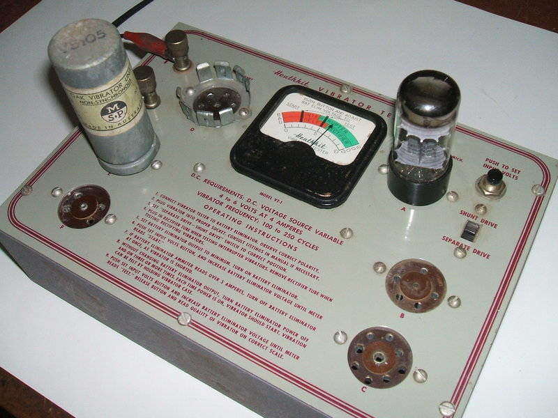
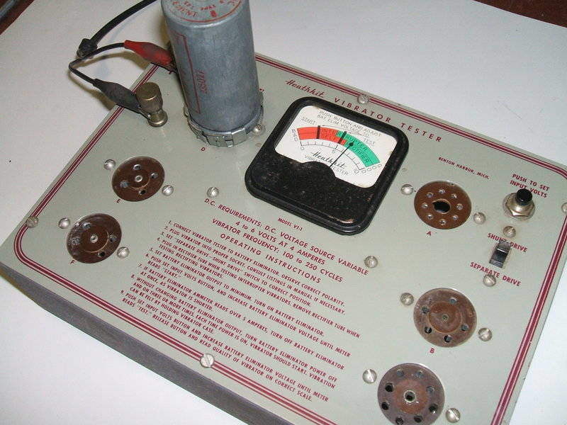
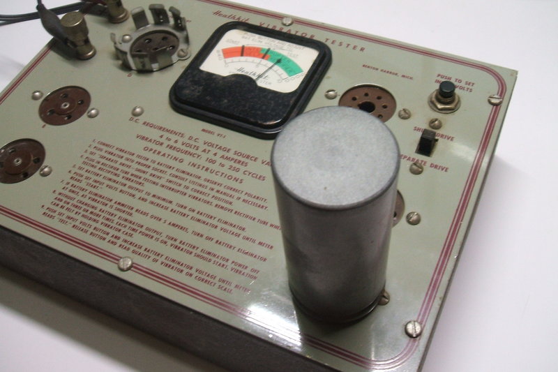
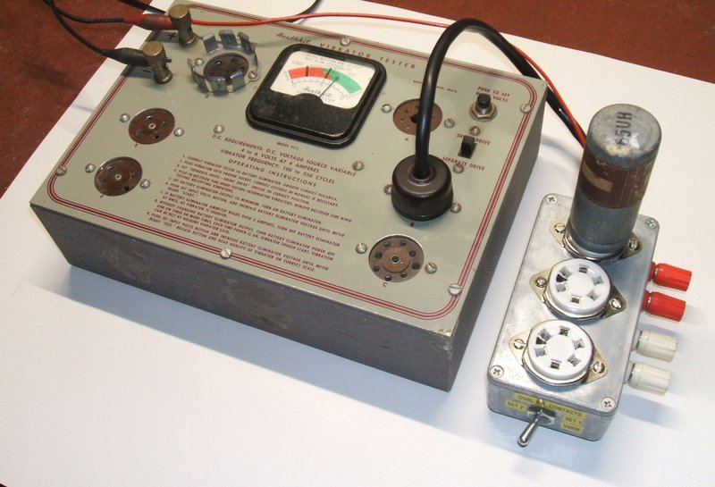
My Heathkit VT-1.
Like most U.S. made equipment in my collection,
this came via eBay. There were only two other bids and as usual, the postage
cost was a lot higher than what the actual tester cost. Condition is very
good, compared to some testers that have appeared.
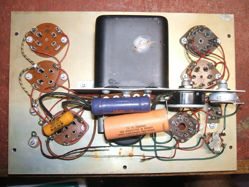
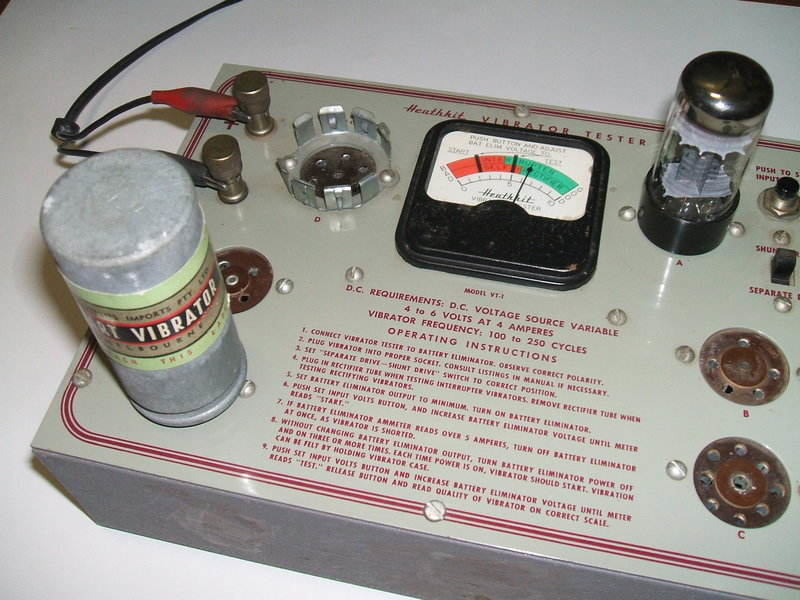
Note the burned wire along the bottom.
It was noticed that at some time a shorted
vibrator must have been plugged in, as the 6V feed wire had the insulation
burned off for most of its length. All components were original. For the
initial testing, I simply used the nearest 4 pin vibrator which was an
ATR 1400. For the rectifier I found a new looking 6X5. A circuit breaker
would have been a worthwhile inclusion to the design.
I noticed first that the "Start" and "Test"
readings were reading low. With the vibrator in and happily buzzing away,
the output meter read about half scale. The vibrator waveform was also
examined on a CRO, and was as it should be. As expected, within a few minutes
the buffer condenser started to fail. This was evident by an increase in
input current, and a warming of the condenser.
The Buffer Condenser.
The value of .006uF is not a preferred
value. So what to replace it with? It so happened I had some 1500V Philips
types rated for pulse operation, .0036uF and .0024uF. In parallel, these
create the .006uF I was looking for. Alas, in circuit something wasn't
right. The vibrator wouldn't start easily, and when it did the waveform
was awful. This was at odds with the original buffer, and temporarily reconnecting
it provided normal operation again.
One characteristic of shunt drive vibrators,
of which the ATR 1400 is an example of, is that starting is erratic if
the circuit loading is not as it should be, and in this case the incorrect
loading was due to insufficient buffer capacitance.
I had been curious that this tester is
claimed to work with vibrators of 100 to 250 c/s. Also, not all vibrators
have the same duty cycle. So, how could they specify a certain buffer capacitance?
Strictly speaking, it's impossible with such a variation in vibrator types.
I can only assume that the Mallory 6VT1
(which this tester is a clone of), was intended only to test Mallory vibrators
which are standardised at 115 c/s. The variation in duty cycle with Mallory
types is not great enough to worry about for the purpose of testing.
Interestingly, when I measured the original
buffer, it was close to .01uF. When I tried a new .01uF, it too worked
correctly with the ATR vibrator. The ATR tested had a lower duty cycle
than a new Mallory, so these findings are perhaps not surprising.
Testing a Mallory "Gold Label" 1601 in the 4 pin socket "E".
Anyway, the next thing to decide is what to do about it. The ideal value of buffer capacitance has been discussed elsewhere on this site. Where a compromise has to be made with its value, it is better to have more than less capacitance. Too low capacitance exposes the vibrator contacts to arcing, and can damage the transformer insulation. Too high capacitance exposes the vibrator contacts to excess current, and while arcing may be eliminated, the incorrect value does not stop contact erosion by electrolytic contact material transfer.
For the VT-1, I settled on the lowest frequency vibrator with the lowest duty cycle that will be tested which is the 100 cycle Oak. The real world buffer capacitance value that suited this vibrator characteristic was again .01uF. Mallory (115c/s) and Ferrocart (150c/s) types were also tested, and as expected, the buffer capacitance was slightly high with the Mallory and higher again with the Ferrocart. However, it was not so high to be problematic, unless the vibrators were run for days on end like that. It is true that I could have included a resistor in series with the buffer to reduce the effects of excess capacitance as described here, but for the purposes of testing, it's hardly worth it.
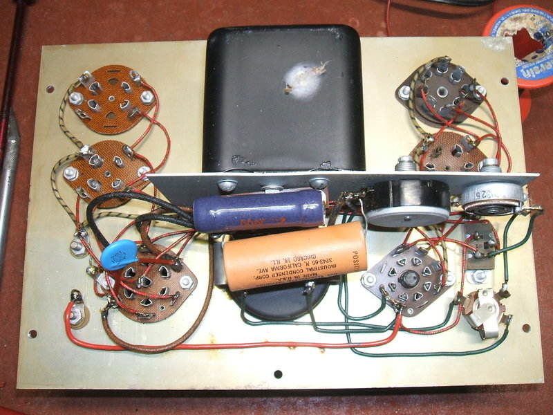
Burned wire replaced along with buffer condenser.
Socket C.
While this socket accepts the unusual
Delco 5 pin vibrator base, the wiring did not match up with the types I
have in my collection. This is because the socket was wired to suit the
Buick type. Seeing as I have a quantity of vibrators using the Delco base,
I rewired the socket to suit types such as Ferrocart PM104, Mallory 245C,
and Delco 5039661. These have different connections to the 273D, 514 and
716 mentioned previously.
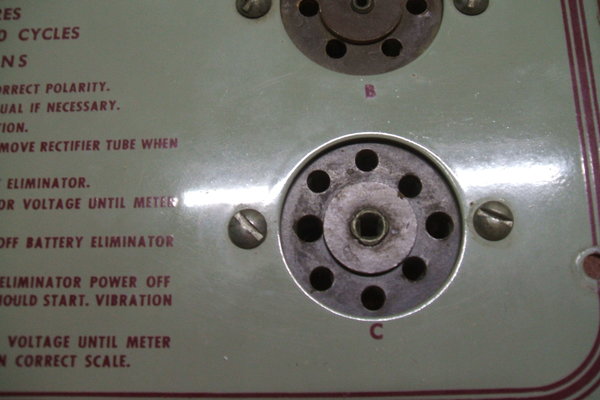
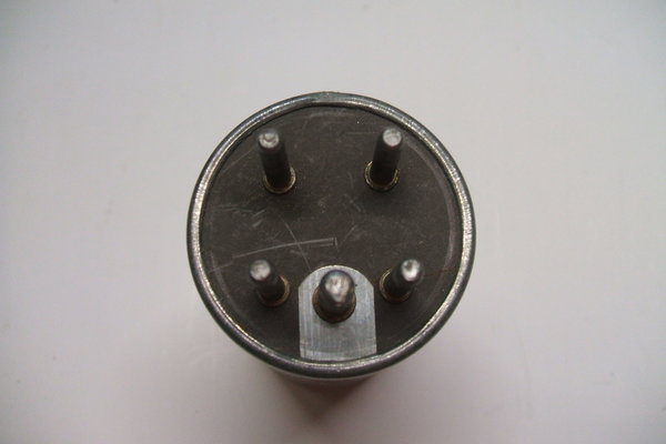
Close-up of socket C. The eight pins are not arranged in a circular
formation. Base of a Mallory 245C is shown at right.
Socket F.
While attempting to test some Ferrocart
vibrators, they would only work in half wave. Even ones which I knew had
good contacts still gave a half wave waveform on the CRO. With an opened
Ferrocart, it became clear what the problem was - the tester socket was
not wired to suit. Transferring the wire from pin 6 to pin 4 fixed that
so both contacts now worked. In retrospect, I could have simply bridged
pins 4 and 6 to allow both socket connections. In reality, this socket
is only likely to be used with Ferrocarts.
The 8uF electrolytic.
Despite its age and the appearance of
something exuding from the seal, it did actually reform with a leakage
current of only 1mA. A peak to peak ripple voltage check showed the capacitance
and internal resistance was quite OK. I did try a new one just for comparison
but there was no difference, so the original stayed.
Calibration.
Not having the instructions for the VT-1,
I had nothing definite to go on, and both calibration pots were obviously
in need of adjustment. However, an article in "Service" for November 1952
did describe the Mallory 6VT1. Unfortunately, it does not say anything
about calibration.
As it's clear that the "Test" line on
the meter is for normal running voltage, it should therefore be set for
6.3V, and this would be a logical adjustment for the 200 ohm pot. This
is what I did, and it turns out the "Start" line on the meter corresponds
with 5V, which is a likely figure.
The output calibration is somewhat arbitrary.
Half scale for a new Mallory synchronous vibrator was a bit low, so I readjusted
the 400 ohm pot for about 3/4 reading. As it happens, there wasn't much
more adjustment available. Even with the pot at maximum resistance it still
isn't possible to reach full scale.
| Scale | Output Volts |
| 1 | 158 |
| 2 | 175 |
| 3 | 191 |
| 4 | 205 |
| 5 | 223 |
| 6 | 241 |
| 7 | 260 |
| 8 | 284 |
| 9 | not tested |
| 10 | not tested |
Further Improvements.
I regard the vibrator waveform to be an
essential part of testing and it is tempting to install a set of terminals
in the side of the tester to connect a CRO. Also, as the range of
sockets is limited, it is tempting to replace socket C with a UX-6
type. I'm loathe to modify commercially made vintage equipment, but there's
any easy way that solves both problems.
Oak V5211 (65UH) split-reed vibrator being tested. Red wire is for
coil supply. Terminals allow monitoring of waveforms.
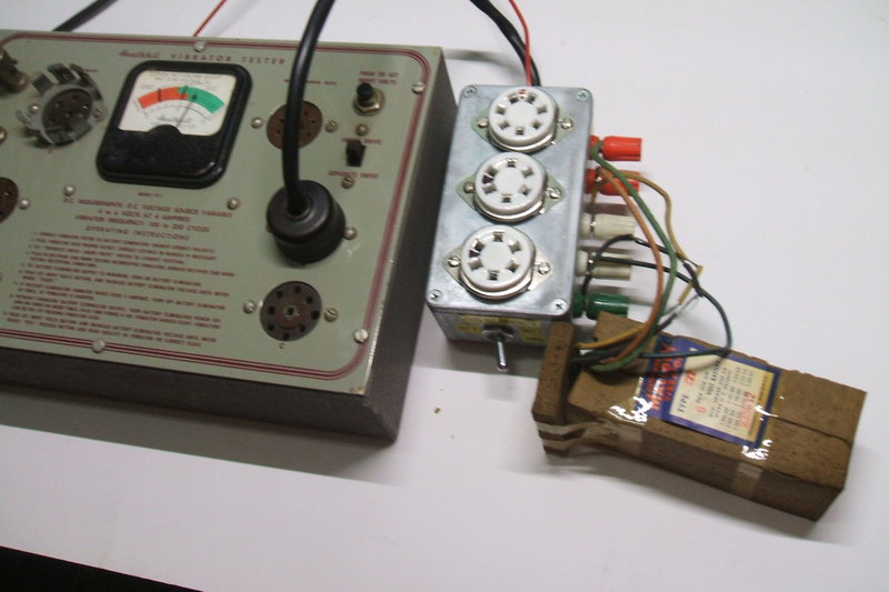
I constructed an adaptor box which makes
the VT-1 much more versatile. A diecast box was fitted with three sockets,
one UX-7 for split-reed vibrators, and two UX-6 sockets; one for synchronous
types, and the other for dual-interrupter types.
This plugs into socket B with a
UY-5 plug. A separate coil supply wire is provided for separate drive vibrators.
This connects to the positive terminal of the VT-1.
Also, terminals were provided for the
primary and secondary transformer connections so that the waveforms can
be observed. This feature can be be used with any of the sockets on the
VT-1 in use (except socket B of course), as the primary and secondary
connections of all sockets are in parallel. The terminals are also useful
for testing wire connected types such as the Mallory 222.
Mallory 222 is a wire connected synchronous type.
The UX-7 base split-reed vibrator is tested
the same as synchronous types. Both reeds are connected together. One of
the UX-6 sockets is wired for dual-interrupter vibrators. A two way switch
selects either set of contacts. Simply wiring the contacts in parallel
would not be an accurate test since one good set of contacts will mask
the others if they are worn or dirty.
Oak type V4006, as used in Ferris car
radios, can be tested in either of the UX-6 sockets as its contacts are
the same as the primary contacts of a synchronous type, or one set of dual-interrutper
contacts. When tested in the dual-interrupter socket, the switch must of
course be set accordingly.
Of course, the 6X5 must be plugged into
socket A when testing dual-interrupter or V4006 types.
In the case of separate drive vibrators,
because of the separate coil supply wire it is now possible to test six
or seven pin vibrators of 4V, 12V, 24V, 32V, or any other voltage in this
tester. The VT-1 is powered from 6V in the usual way, but the coil is connected
to another power supply of suitable voltage. As the drive coil in separate
drive vibrators is not connected to the transformer switching contacts,
the contacts do not have to work at the same voltage as the coil.
Oak types V4010 and V4016 are shunt driven but with a separate drive contact. They are fitted with a UX-6 base. I have not provided for this type yet, but may do so in the future by adding suitable switching for one of the UX-6 sockets.
Incidentally, the quality of the UX-6 sockets I used is very poor. They were purchased from eBay from a Chinese seller. The contacts have no springiness in them and do a poor job of gripping the pins. In fact, the contacts would drop out of the socket until I splayed them apart more. Unfortunately, buying decent sockets from the U.S., such as those made by Amphenol or Cinch, means an exhorbitant postage cost. The UX-7 socket looks like it came from the same factory but seems to be a bit better.
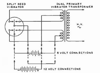
A note on Split Reed types.
It is important to know that there are
two types of split-reed vibrators. One is the usual self rectifying (synchronous)
type such as Oak V5211. As with the standard synchronous types, the secondary
contacts close later and open earlier than the primary contacts.
However, in the U.S. another kind became
popular in the late 1950's. With this type, the vibrator is actually a
dual-interrupter, or to use the U.S. term, a "Duplex" type. Common types
are the Mallory 1701 or CDE 5722.
Both sets of contacts are timed the same
in standard dual-interrupter fashion. Rectification is done with solid
state or valve rectifiers. To understand why this type came into being,
remember that there was a sudden change in U.S. automotive electrical systems
starting in 1953. All the car manufacturers had switched from 6V to 12V
within a few years. With many commercial vehicles fitted with new 6V communications
equipment, a problem existed in that when the vehicle was traded in the
following year, chances are there would be a 12V system to contend with.
To retain the radio equipment would entail modification; installation of
a new transformer and vibrator being part of it.
An ingenious way around this was to have
a transformer with two 6V primary windings; each operating with their own
vibrator contacts. For 6V operation, both circuits would operate in parallel.
But, for 12V, the circuits would be in series. The vibrator drive coil
would operate off the supply at the mid point of this series circuit. Thus,
no change of vibrator or transformer would be required.
Therefore, these types should be tested
as dual-interrupter types and not synchronous, despite the pin connections
being the same. It is true they will self rectify, and will actually test
OK in the VT-1 as a synchronous type, but this won't give a true indication
of the second contact set since the current is much less than when the
contacts switch primary current.
Furthermore, some types are marked with
"6 or 12" volt operation. The coils are actually 6V, and the dual voltage
marking simply indicates the vibrator does not need to be replaced when
the circuit is switched for 12V operation. It does not mean the
coil is suitable for both voltages! If the vibrator is used in a more conventional
circuit, it is necessary to connect a resistor in series with the drive
coil pin when 12V operation is required.
For reasons of efficiency and contact life, dual-interrupter and synchronous types should not be interchanged.
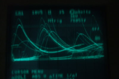
This waveform was so destructive I didn't want to spend too long
photgraphing it. Arcing was evident at several points.
It must be remembered that as a tester, the VT-1 will have unknown vibrators plugged into it and these kind of operating conditions can occur. The problem is that if arcing is sustained, carbon tracking will develop in the socket wafers. This of course is conductive, and the sockets are ruined. Worse still, there's a good chance of a breakdown in the transformer. Obviously, some kind of clamp is needed to limit the output voltage under fault conditions. The danger occurs when testing non-synchronous vibrators before the rectifier has warmed up. Given the 250V per side rating of the transformer, a mains voltage VDR is an ideal choice. A type S20K300 was chosen. It clamps at 300V.
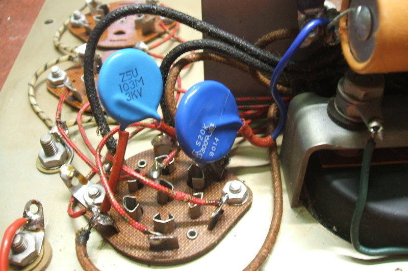
VDR is connected across one half of the transformer secondary.
This worked very well. Under normal conditions, no current flows through the VDR, and the waveform is as it should be. Under fault conditions, the voltage is clamped and no arcing takes place. About 6mA was observed to flow through the VDR. This was not an accurate measurement, given the waveform, but proves the VDR is conducting. The particular vibrator used for these tests was an ATR 1400 which was out of adjustment, so that that duty cycle was shorter than normal, and starting was erratic (it's a shunt drive type). Starting did not usually occur unless the 6V was rapidly applied several times.
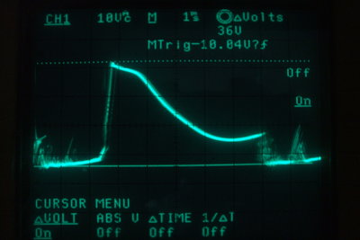
With the VDR, the voltage is clamped to a safe level. It can be
seen the vibrator is operating in half wave with a short duty cycle. With
certain transformers, excess voltage is produced.
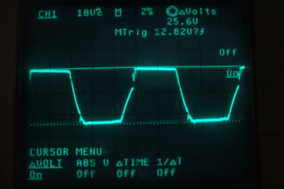
What the waveform was with an almost correctly working vibrator,
when the vibrator did start properly. The duty cycle is shorter than it
should be and the buffer capacitance is only just adequate for these conditions.
The VDR appears open circuit under these conditions.