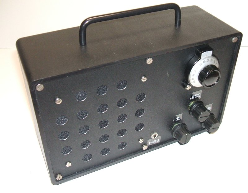
This fully portable receiver has superhet sensitivity and selectivity. Speaker is 4".
This fully portable receiver has superhet sensitivity and selectivity.
Speaker is 4".
This MW receiver is based on the ETI-062
"Simple AM Tuner" which appeared in ETI for March 1977. It was also published
in ETI's "Project Electronics", a compilation of various ETI projects.
The now defunct Dick Smith Electronics sold kits for each of the projects,
but in 1980 DSE published their own project book "Dick Smith's Fun Way
into Electronics" and Project Electronics faded into history.
For non Australasian readers, ETI was
"Electronics Today International", an Australian based electronics magazine,
which in the 1970's and 80's was the main competitor to "Electronics Australia".
ETI did not specify any particular method of construction or use
of an enclosure.
My first experience with the ETI-062 goes
way back to 1978. Unfortunately, with very little knowledge of electronics
at the time, I was not successful with the kit.
Around 1986, frustrated with ZN414, and
not knowing how to improve its performance, I decided to re-visit the ETI-062.
I simply built the circuit up on a breadboard and was quite astounded at
its performance. [An improved circuit configuration was developed for
the ZN414 which resulted in considerable improvement. See
here.]
It didn't take long to notice the amazing
sensitivity and selectivity, which was on par with a superhet. It was quite
a simple matter to listen to 3XY from Melbourne in Sydney at night with
just the ferrite loopstick aerial. I ordered the printed circuit board
from RCS radio to make a more proper construction of the circuit. This
was simply mounted on a piece of wood, with an aluminium front panel to
support the speaker, dial, and other controls. A two transistor amplifier
was used to drive the speaker.
The ultimate goal was to make a portable
receiver out of the ETI-062, but that took another 30 years to get around
to!
The ETI-062 Circuit.
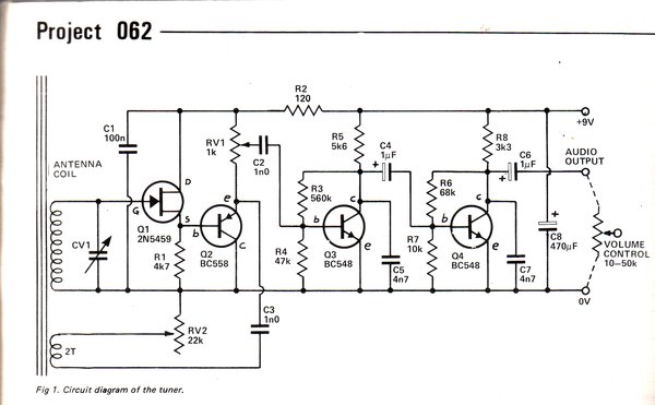
The design of the circuit is unlike anything that I have seen published anywhere else. Although the article did not give the author's name, it appears credit must go to Barry Wilkinson, one of the project designers for ETI. It is the unconventional design which is behind the unusually good performance. It is certainly not "just another regenerative receiver"!
Unlike most solid state regenerative receivers,
this one does not need a low impedance winding on the aerial coil to feed
the first transistor. This is because the first transistor, Q1, is
a FET. Not only that, the FET is connected as a source follower, with R1
as its load. The result is an extremely high input impedance seen by the
aerial coil. The Q of the tuned circuit remains high, and good selectivity
is retained. Q2 is a buffer connected as an emitter follower, which reduces
loading on the FET. The output of Q2, which is the amplified, but undetected
AM signal, proceeds two ways. One is to the detector, Q3, via an RF gain
control. This transistor has its bias set so it operates in class B, and
thus detects the AM signal. At the collector of Q3 is the recovered audio
signal. C5 filters residual RF.
Q4 provides further audio gain prior to
feeding to an external audio amplifier. C7 provides final filtering to
any RF that may be present.
The second signal path from the output of Q2 is to the regeneration circuit. This consists of two turns of wire around the ferrite loopstick, and a 22K pot to adjust the amount of out-of-phase signal fed into this coil. In strong signal areas, ETI suggested the regeneration circuitry was not required, and this was found to be true. In this case it becomes a local station only receiver.
ETI's suggestion was to feed the audio into their ETI-061 amplifier, a simple four transistor complimentary symmetry design. I'm not a fan of class B amplification, so I used a two transistor class A design instead. On its own, the ETI-062 will drive headphones, despite the poor impedance matching. Obviously, the higher the impedance of the phones, the louder the sound will be. I found 8 ohm phones to be tolerable in a strong signal area.
Construction of a Portable Receiver.
The receiver was built on an aluminium
chassis, attached to a Marvi-Plate steel front panel. This assembly slid
into a plastic case with a handle and internal battery.
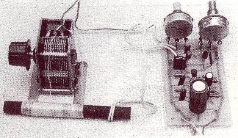
Rear view of chassis. The PCB is between the tuning condenser and
the chassis. On the right side of the chassis is the audio amplifier and
output transformer.
The tuned circuit consists of a ferrite loopstick with pre-wound coil, once sold by Jaycar. The tuning condenser is an obsolete MSP (AWA) type which is adjusted by a miniature vernier dial on the front panel.
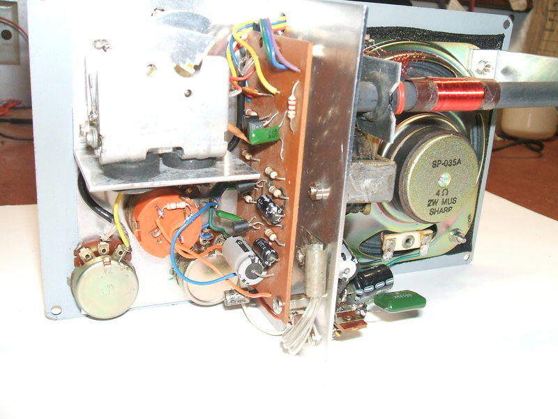
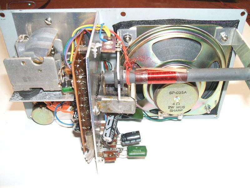
Closer view of the RF section. The audio output transistor is visible
in its heatsink at the rear of the chassis.
Underneath the vernier dial are the three other controls; regeneration, RF gain, and on/off volume. The pots also secure the chassis to the front panel. On the other side of the chassis is the aerial coil, audio amplifier, and 4" speaker.
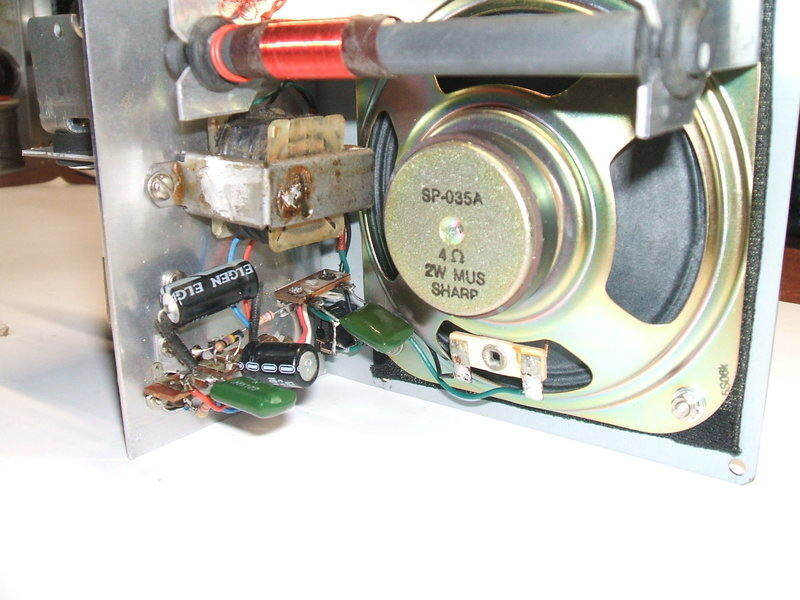
Close-up of the audio amplifier circuitry.
The loopstick was mounted on brackets sharing
the upper speaker bolts. 3/8" rubber grommets secure the rod in the brackets.
Note that the brackets are notched at the grommet holes to eliminate the
shorted turn that would otherwise be formed.
The audio amplifier was built on tagstrips
and the transistors mounted in sockets.
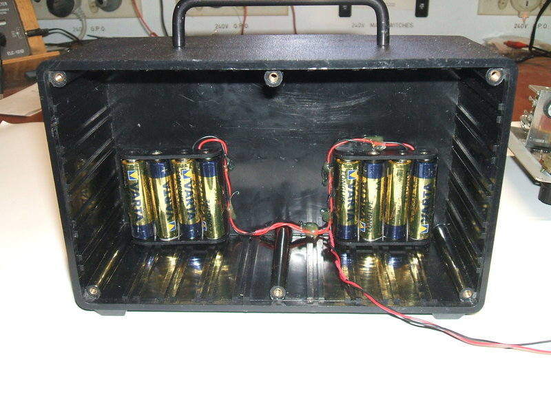
8 x AA cells provide power for the receiver.
I considered several options for powering
the receiver. However, I had to keep in mind that once the chassis was
in the enclosure, there wasn't actually a lot of room left. I had a 14.4V
Li-Ion battery which would have been an ideal choice otherwise. This would
necessitate the use of a special charger circuit to balance the charge
for each cell, but these are available cheaply on eBay pre-assembled -
which they really need to be, because of the surface mount components.
Ni-Cd's are of course an option and easy
to
charge. As the audio amplifier needs 12V, this would require 10 such cells.
The off putting feature however, is they're liable to leak. Batteries are
by their nature chemically unstable. In my years of servicing, batteries
would have to be the most problematic component, before modern electrolytic
capacitors - another chemically unstable component. Left unattended, most
batteries will release their corrosive electrolyte. At best it goes no
further than the terminals. At worst, the corrosion travels along the connecting
wires to the PCB or switch. Additional to this is the incidental corrosion
of nearby metallic parts.
Out of the lesser of evils, I chose AA alkaline cells. These are cheap if bought from the right place. In view of the convenience, this the choice I took. Unfortunately, many types of alkaline cell start leaking early on, well before their capacity has been used up. This seems to be a recent phenomenon too. I don't ever recall Duracells or Energizers leaking back in the 1990's.
Two four-cell AA holders were mounted on the back inside the case. As the plastic here is thick enough, I was able to use short 2.5mm screws tapped into the plastic to secure the holders. Hot melt glue was used to secure the wiring.
Circuit of the new receiver.
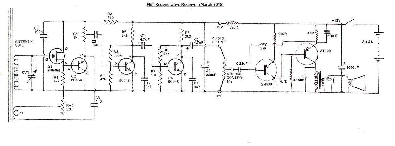
Due to components I had available, a slight
departure was made with some capacitor values in the ETI-062 circuit. C4
and C6 are now 4.7uF. C8 was changed to 220uF. These values are non critical
and have no effect on performance. The ETI-062 is fed from the 12V supply
via a 390 ohm decoupling resistor.
Audio Amplifier.
Turning now to the audio amplifier, two
PNP germanium transistors are used. These, and the output transformer were
obtained from the remains of an Astor G5G portable radiogram.
The circuit is one I've used many times
before. However, because of the PNP transistors and the positive supply,
the amplifier circuit is connected upside down so the transistors receive
the correct polarity.
The first transistor is a 2N408 and this
is direct coupled to the output transistor, an AT128. This is just Astor's
in-house version of the AC128. Output transistor current is stabilised
by the 47R emitter resistor. Current through this provides bias to the
2N408. If the AT128 emitter current increases, the 2N408 is biassed harder
on, removing bias current from the AT128, and so its current drops. It
is an effective stabilising circuit which allows for quite some variation
in transistor characteristics. Output transistor current is 30mA to suit
the output transformer.
The output transformer has an impedance ratio of 375R to 4R. In its previous life, it operated into a 3.5R speaker, but the half ohm difference is trivial. Because of its large core size, bass response is very good. The speaker is a 4" 4 ohm type. Included in the speaker circuit is a stereo 3.5mm socket for headphone use. Both left and right channels are connected in parallel.
Because of the very high audio gain of
this circuit; Q3, Q4, the 2N408, and AT128; instability will occur at anything
more than a moderate volume control setting. Output of the ETI-062 is not
quite enough to drive the AT128 to full output on a weak station, so the
2N408 is required. However, gain is then too high. To bring the gain down,
the 2N408 emitter circuit has a 220R resistor to provide degeneration.
Voltage gain from the 2N408 base to the
speaker voice coil is 13.6 times. Sensitivity is 87mV P-P. Output power
before clipping is 44mW. That may sound like an absurdly low power, but
with a good sized baffled speaker it easily provides room filling volume.
It is well to remember that most domestic audio equipment is normally operated
at less than 100mW, despite, say, the typical 3W rating of a mantel radio.
Performance.
The first thing that strikes the user
is the selectivity. With critical adjustment of the regeneration control,
the bandwidth can be reduced to the point where the higher frequency audio
components are lost. Selectivity is knife-edge, and with the regeneration
adjusted correctly, the vernier dial is really needed. Needless to say,
stations on nearby frequencies do not cause interference.
Because of the incredibly high Q of the
tuned circuit, anything brought near the ferrite loopstick will detune
the receiver. Once the receiver is placed on a table and tuned in, this
is not a problem, but if it is then lifted by the handle, the tuning will
shift slightly.
The regeneration control is really the only deficiency with this receiver. Unfortunately, it suffers backlash. That is to say, if the control is taken just a little to far, the receiver bursts into oscillation and the control has to be turned back considerably to stop it. For distant station reception, tuning the receiver requires steady adjustment of the regeneration control while the tuning is adjusted, not letting it go over the threshold.
For all the years I've used this receiver circuit, I have not once found the RF gain control necessary. Conceivably, the detector could be overloaded in areas of high signal strength, which is why it was included. The idea of using the RF gain control as the volume control, allowing the omission of the normal volume control is interesting in that one control could be eliminated. It does actually work in that the volume can indeed be controlled. But, a few problems make it impractical to use it this way. Firstly, the audio amplifier is operating at full gain all the time, the result of which is some noise audible at "low volume" settings. There isn't the audio amplitude sufficient to mask it. Secondly, there is DC flowing through the RF gain control pot which results in a small scratching sound as the pot is rotated. And, thirdly, there is a slight interaction between the RF gain control and regeneration circuit, which becomes evident when the regeneration is critically set.
Both sensitivity and selectivity are the same as a superhet with a ferrite loopstick. In some instances it's better. This receiver is quite suitable for DX reception.
Update 27/02/23: It was discovered that at anything above low volume settings would result in supersonic oscillation in the audio amplifier. While not audible, it caused an increase in battery drain, as well as reducing sound quality. The amplifier was modified thus:
Improved Audio Amplifier 21/07/25.
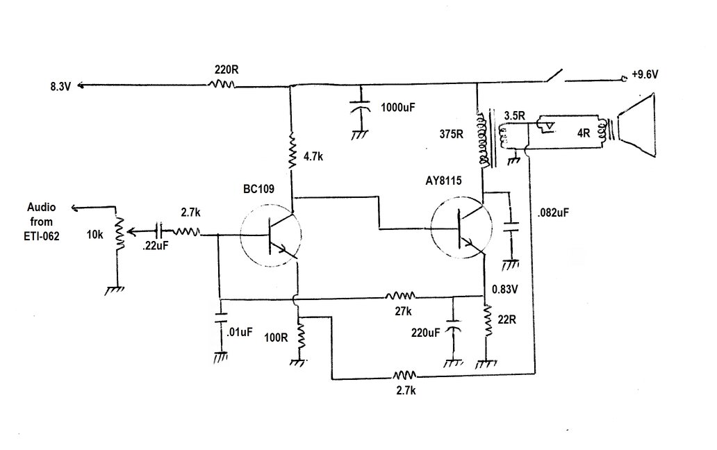
The amplifier section has been rebuilt
using NPN silicon transistors. I discovered that the current consumption
had been creeping up over time with the germanium transistor circuit, possibly
due to the transistor leakage, and the previous modification had not fixed
a problem which had always been evident.
That is, there was some motorboating at
high volume. This was largely due to the use of PNP transistors. Since
the tuner section is all NPN, the earth is referenced to the negative rail.
However, with the audio amplifier using PNP transistors, its earth is referenced
to the positive rail. Effectively, the two earths are not a solid connection,
because of the 390 ohm decoupling resistor. While the supply rail bypass
capacitors go a long way to help, they are still not perfect.
As much as I like germanium transistors,
they just weren't really compatible with the tuner circuit. Another modification
was to change the AA cells to NiMh. NiMh cells seem to be less problematic
with leakage than NiCd types. AA alkaline cells are now made without mercury,
which means they will eventually leak, so they are best avoided.
However, since the battery holder is for
eight cells, this means the supply voltage would drop to 9.6V. This is
not a problem in itself, since the tuner works over a wide voltage range.
In fact, the regeneration control is easier to adjust at lower supply voltages.
It does mean that the collector current of the output transistor has to
be higher, to get the same power output. In view of the reduced voltage,
the 390 ohm decoupling resistor was reduced to 220 ohms.
The amplifier is based on a circuit I've
used many times before. It's used in the solid
state pulse counting receiver, and also the reflex
receiver, among others. It's a two transistor direct coupled design,
with the first transistor receiving its bias from the emitter of the output
transistor. The circuit is self stabilising. If the emitter current increases
in the output transistor, the first transistor receives increased bias,
which then reduces collector voltage, and thus the base current for the
output transistor.
Emitter current is 38mA. This allows full
output to be obtained with the 9.6V supply, and the impedance of the speaker
transformer used. Power output is 67mW before distortion becomes obvious.
This is actually an improvement in itself over the previous design.
Negative feedback is included in the emitter
circuit of the first transistor. Given the very high audio gain of the
whole circuit; effectively five transistors worth, stability is important.
Since silicon transistors have a very high frequency response, there were
problems with RF getting as far as the output stage. To fix this, the output
transistor collector was bypassed with 0.082uF, the input transistor base
bypassed with 0.01uF, and a base stopper resistor of 2.7k included.
Now, the ampifier can be operated at full
volume without any instability.