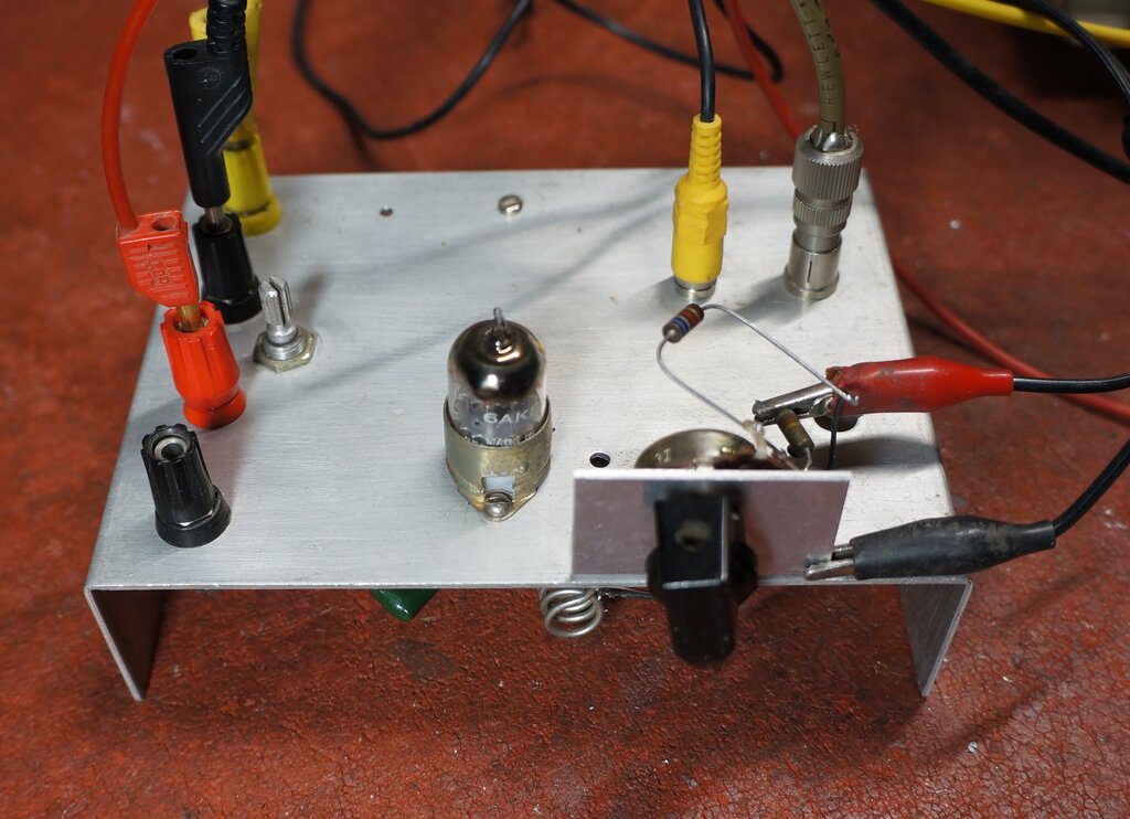
No variable capacitor! Varicap diodes allow for potentiometer tuning remote from the receiver.
No variable capacitor! Varicap diodes allow for potentiometer tuning
remote from the receiver.
The purpose of this project was to design
a super-regenerative receiver for the VHF FM broadcast band, which could
be tuned with varicap diodes, and did not require a user adjustable regeneration
control. This was all part of the design and construction of a radio to
be installed in the Jeep.
The Jeep radio will be constructed in
three units. These are: 1) Power supply and receiver unit, 2) Speaker
with output stage, and 3) Control unit. This is necessary because of the
available space and dashboard layout. Since the control unit is located
separately to the receiver, a difficulty occurs with remotely tuning the
VHF circuit.
In the past, Bowden cables were used with
two unit car radios, to provide a mechanical coupling between the control
unit, and the variable capacitor inside the receiver unit. In the modern
day, obtaining or making the mechanical parts required would be very difficult.
I have been through this exercise before, with the Model T radio. It is also a two unit set with speaker. The obvious solution there was to use varicap diodes to tune the receiver, since all that is required is a variable DC voltage. The tuning control then becomes a potentiometer, which can be located at any distance from the receiver. Unfortunately, varicap diodes are completely out of character for something that was intended to be of the valve era, but we have to be practical, if we want a radio for the Jeep (or Model T)!
Having dealt with the tuning, the next
thing is the regeneration control. Experience has shown that user adjustable
regeneration controls are undesirable for a car radio. It is a major distraction
to the driving, and a two handed tuning operation is obviously impractical.
Recent super-regenerative receiver designs,
as described on this site, have included stabilising circuits, which go
a long way to minimise regeneration control adjustment.
While the Model T radio works well, and
seldom requires regeneration adjustment, I wanted to see if this could
be improved on. If no improvement was possible, the Jeep radio could simply
use the same receiver design.
Using a Fremodyne circuit would of course solve the automatic regeneration control problem. It was considered, but with more parts required, and the limited space available, it could end up being quite cramped.
Varicap Diodes.
Evident from the Model T radio is that
varicap diodes have a much lower Q, compared to an air spaced variable
capacitor. This is a problem with a self quenched super-regenerative detector,
because the oscillation must be very strong. It has to be strong enough
to bias the valve into cut-off. The lower Q makes this difficult, and medium
gain valves like 6C4 and 7193, will not super-regenerate properly, despite
working perfectly well with a mechanical variable capacitor.
The varicap diodes I used in the Model
T radio, and for this experiment, were Motorola types MV2109. These are
1980's era components, which would probably be difficult to obtain now.
Their Q seems to be much better than the Philips BB105G.
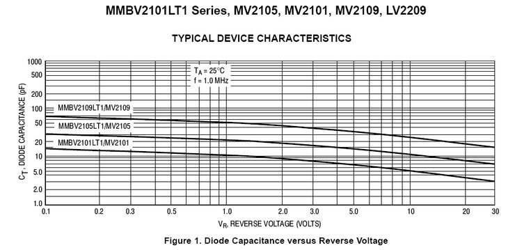
Characteristics of the MV2109 varicap diodes.
Varicap diodes are used with reverse bias. The more reverse bias, the less the capacitance. In this circuit, two diodes are used, connected back to back with the anodes together. This is done so that the voltage developed across the oscillator coil cannot forward bias either of the diodes. If only one diode is used, and the oscillation voltage is high enough, the diode will conduct and restrict the tuning range. Of course, when two varicap diodes are connected in series, the capacitance range is halved.
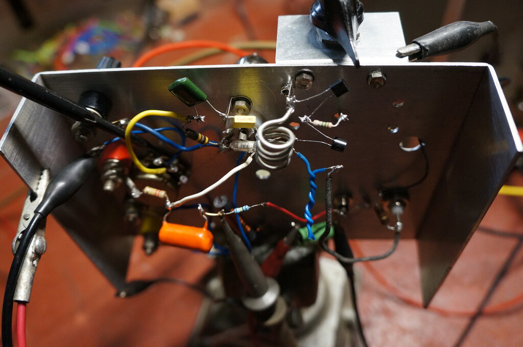
Varicap diodes can be seen connected across the oscillator coil.
It should also be obvious that the voltage fed to the varicap diodes must be very well regulated, if tuning drift is to be avoided.
Automatic Regeneration Control.
My first attempt at making the regeneration
control automatic used cathode stabilising. Oscillation level is dependent
on cathode current, so if the cathode current can be stabilised, then so
should the oscillation level. This method uses a cathode resistor, suitably
bypassed, and works the same as any cathode bias circuit. That is, if cathode
current increases, negative bias on the grid increases, so reducing the
cathode current, and vice versa. The Model T radio uses this method. In
practice, it is rarely necessary to adjust its regeneration control.
More recently, experiments have been done
with grid stabilising circuits. I first experimented with this method here.
Typical of receivers using it is this 7193
circuit.
As mentioned previously, the level of
oscillation is dependent on cathode current, and thus the grid bias. For
this method of stabilisation, the rectified grid voltage, which occurs
as part of the oscillation, is itself used as the bias voltage. A negative
voltage appears at the grid because of the charging and discharging of
the grid capacitor (33pF), through the diode formed between the grid and
cathode. The greater the oscillation, the greater the negative voltage,
and the greater the current through the grid resistor.
If the grid resistor current is used to
charge a capacitor, we then have a negative DC voltage across this capacitor,
proportional to the oscillation level. So that this level of DC can be
adjusted, more or less current is shunted to earth by a resistor across
the capacitor.
For example, if the capacitor charges
to -2V, this is exactly the same as biassing the grid circuit to -2V from
any other source. The greater the oscillation, the higher the bias, and
the subsequent reduction in oscillation.
Somewhat coincidentally, I later discovered both methods of stabilisation were also used with the Fremodyne circuit. At the time I had not realised this, since it was prior to obtaining the patents for, and fully understanding, the operation of that circuit.
First Tests.
Seeing as one of the goals was to eliminate
the regeneration control, the first test was to test one of the simple
grid stabilised circuits. The first immediate difficulty, however, was
covering the full FM band with the varicap tuning.
Yet, the Model T radio, using the same
type of varicap diode did not have this problem. A little investigation
into the characteristics of the valves I was attempting to use explained
this. The test panel has a 7 pin valve socket, and valves I tried were
initially types like 6AU6, 6BZ6, 6GK5, and 6AM6. While all these types
will oscillate at VHF, there's the question of input capacitance.
| 7193 | 2.2pF |
| 6C4 | 1.8pF |
| 12AT7 | 2.2pF |
| 6AK5 | 4pF |
| 6CB6 | 6.5pF |
| 6EW6 | 10pF |
| 6GK5 | 5pF |
| 6AM6 | 7.5pF |
| 6BZ6 | 7pF |
This explains why the Model T radio had
sufficient tuning range. It uses a 12AT7 with an input capacitance of only
2.2pF. At the other extreme, 6EW6 has 10pF of input capacitance. That is
enough to tune half way across the FM band! The problem here is the restricted
tuning range of varicap diodes. In the case of receivers using mechanical
tuning capacitors, the capacitance range is much greater, so this is not
so much of a limitation.
Having discovered this, the next thing
to do was choose a more appropriate valve. As mentioned before, type 6C4
or 7193 hasn't enough gain to oscillate to the required degree in the low
Q circuit. However, the 6AK5 looked promising. It would also fit nicely
into the WW2 theme.
Indeed, this valve worked exceptionally
well, oscillating possibly more readily than any other type I've so far
used. It was still self quenching nicely with under 50V B+ and
varicap diodes! Because the 6AK5 oscillates so easily, it means a higher
than normal plate load resistor can be used. This results in a noticeably
higher audio output. Typically, 1.3Vp-p was produced by weak stations,
increasing to about 3.8Vp-p on strong stations. Another characteristic
is the lower cut off voltage, which assists with self quenching. Previous
experiments with pentodes showed no advantage in providing a separate screen
grid supply, so the 6AK5 was connected as a triode.
While not tested, it's possible that the
lower Q, but more easily available BB105G diodes might work.
Circuit 1.
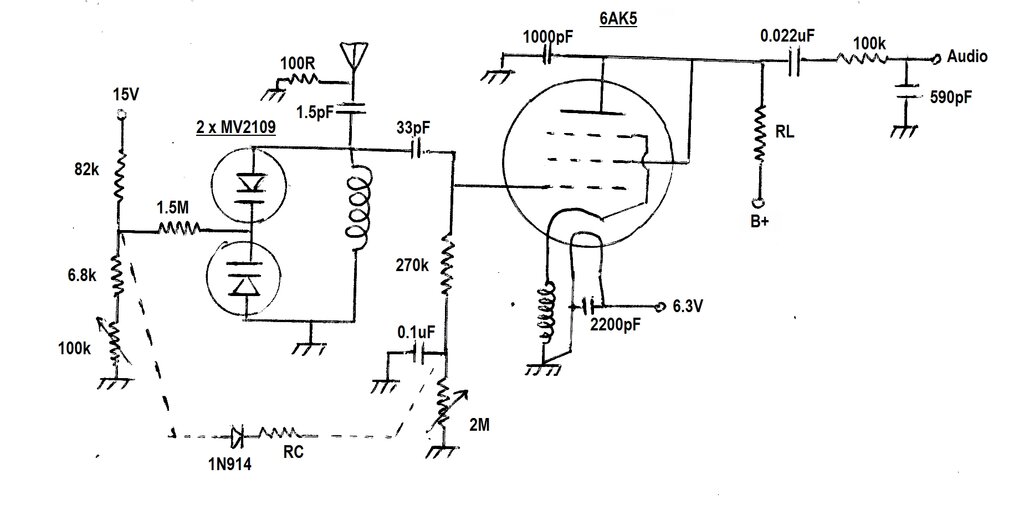
Grid stabilised 6AK5 circuit for first test.
As can be seen, the basic circuit is the
same as others which I've described elsewhere on the site. It is a basically
a modified Colpitts oscillator, relying on the capacitances across the
cathode choke, and between the grid and cathode, to oscillate. It self
quenches in the usual way, with the voltage across the 270k grid resistor
building up high enough to cut the valve off, causing a cessation of oscillation.
The process repeats, depending on the time constant formed by the 33pF
and 270k. This is the quench frequency, which is in the realm of 35 kHz.
The 1N914 and RC will be mentioned later,
and are not part of the original test circuit.
Tuning voltage is provided by the 100k pot, which is supplied through the 82k and 6.8k resistors from a regulated 15V supply. The pot is wired as a shunt resistor rather than a voltage divider, so that only one wire and an earth is required. This is to simplify the connection to the remote control unit, by eliminating one wire. Unfortunately, this method results in non-linear operation, with stations cramped together at the low end of the band. This can be offset to some degree by using a pot with a logarithmic curve. The 6.8k sets the lowest oscillation frequency, while the 82k sets the highest.
Because of the LC ratio of the tuned circuit, the amplitude of the oscillation varies as the receiver is tuned across the band. At the 88 MHz end, the ratio of capacitance to inductance is less than at the 108 MHz end. The more capacitance, the less the circuit wants to oscillate. As such, the regeneration requires adjustment in conjunction with the tuning, if performance is to be consistent across the band. The regeneration needs to be increased as the receiving frequency is decreased.
It has been found the best method of adjusting the regeneration is to take the grid resistor to a more or less negative voltage. Other methods commonly seen elsewhere, such as adjusting plate voltage, result in inferior sensitivity.
6AK5 with Grid Stabilisation.
With the recent success of the grid stabilising
circuit, I naturally applied it to the circuit under test, using the 6AK5.
Here, the current flowing in the 270k grid resistor charges the 0.1uF capacitor
to a negative voltage. The voltage is set by the 2M pot shunted across
the capacitor. The higher the oscillation amplitude, the greater the negative
voltage.
Alas, results were only good up to a point.
The problem was a marked drop off at the 88 MHz end of the band. It was
found the quench frequency was increasing to virtually double what it was
at 108 MHz. As quench frequency is raised, the sensitivity and audio output
level drops off. Ideally, the quench frequency should remain around 30-35
kHz across the band. This effect was not greatly influenced by the value
of load resistor or B+ voltage.
Measurements were taken with various load
resistors and B+ voltages. Setting the regeneration control at the 108
MHz end of the band provided the following results:
| RL & B+ | Vg 88 MHz | Vg 108 MHz | fq 88 MHz | fq 108 MHz |
| 230k @ 240V | -1.34 | -3.24 | 57 kHz | 28.6 kHz |
| 150k @ 150V | -1.21 | -2.26 | 65 kHz | 35 kHz |
| 56k @ 100V | -1.31 | -2.17 | 59 kHz | 34.2 kHz |
With varicap diodes, the situation is worsened
because the Q decreases with capacitance. Thus, the Q is less at the 88
MHz end of the band, where oscillation is already difficult.
To compensate, it then becomes necessary
to reduce the negative grid voltage (Vg), to decrease the quench frequency.
Since the tuning control provides an increasing
positive DC voltage as the receiving frequency is increased, could we not
use this to compensate? This is where the 1N914 and compensating resistor,
RC, come in. By offsetting the negative grid voltage (Vg) with the tuning
voltage, it should provided the desired effect. So that the negative grid
voltage could not affect the tuning voltage, the 1N914 diode was included.
The compensating resistor value was not measured, but was a 3M pot in the
test circuit. The resistance was at least 1M.
It worked to a degree, except the compensation
was not as linear as desirable. It was also felt that this solution was
really masking the problem, rather than actually compensating for it. The
degree of automatic stabilisation would be reduced, as the tuning voltage
was increased
Circuit 2.

Cathode stabilising circuit added.
Remembering the cathode stabilised circuit
used in the Model T radio worked quite well, the next test was to see how
well it would work with the 6AK5. The 2M pot was reduced to 0 ohms, and
the cathode stabilising components introduced; these being the 10k pot
and 22uF bypass capacitor. Since the 'problem end' was at 88 MHz, the cathode
resistance was adjusted to optimum operating conditions at this frequency;
i.e. a quench frequency of 34 kHz. When tuned to 108 MHz, the quench frequency
decreased to about 30 kHz.
This in itself was a huge improvement
over the grid stabilising circuit on its own.
What if the grid stabilising circuit was also used? With the receiver tuned to 108 MHz and the quench frequency still 30 kHz, a slight adjustment of the 2M pot brought the quench frequency back up to 34 kHz. Importantly, when the receiver was tuned back down to 88 MHz, it was still 34 kHz!
Mission accomplished!
The operating conditions were optimised. Less intermodulation distortion was had by using a quench frequency of 30.4 kHz.
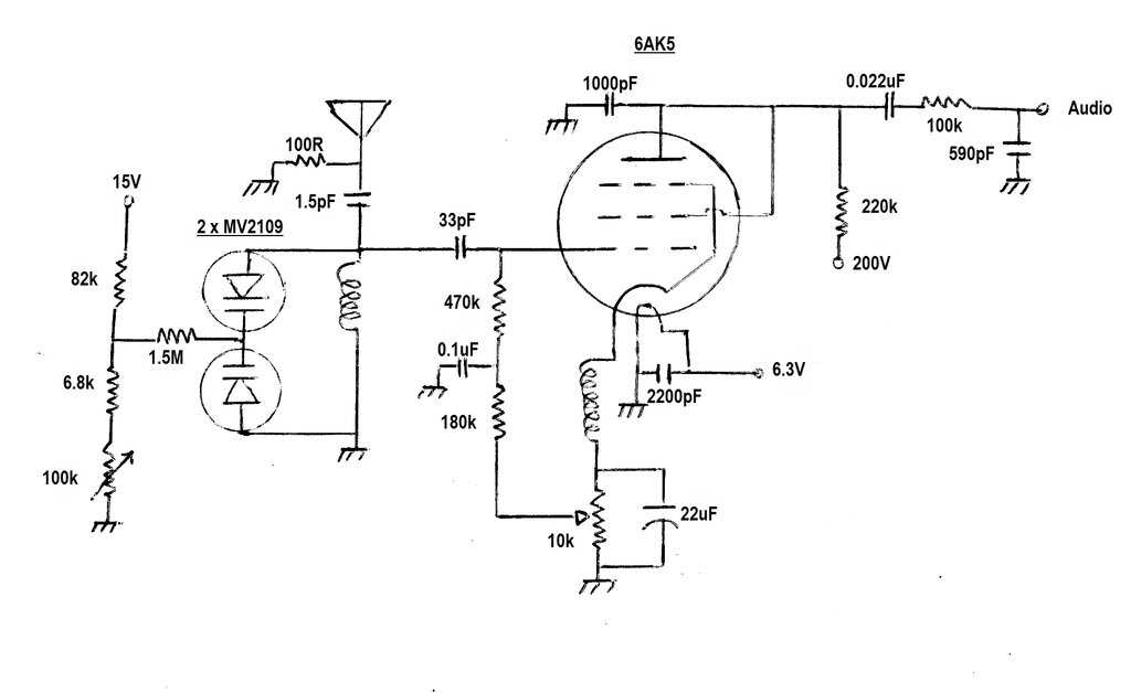
The adjustment of Rg (the 2M pot) was not critical, and it seemed acceptable to replace it with a fixed resistor. This would mean only one preset adjustment was required. The final circuit is shown above. The 10k pot can be wired as a rheostat if desired, with the 180k resistor earthed. The result is electrically the same. The optimum resistance in the test circuit was 2.46k, which means a 5k pot could be used instead.
Quench Frequency vs. Signal Strength.
It is important to note that because the
stabilising circuits also act on signal strength, the adjustment must be
done with no signal. It will be found that quench frequency increases with
signal strength. This is actually an ideal situation, because it provides
an additional AVC effect, to that already inherent in a super-regenerative
detector. A higher quench frequency is desirable for sound quality, but
because of the desensitising effect, is unsuitable for weak signals. However,
in this instance, the quench frequency is automatically decreased for weak
signals, where it's needed, and increased for strong signals where sensitivity
is less important.
It is now an interesting proposition to modify the Model T radio, with the simple addition of one resistor and capacitor, to remove any need for its regeneration control adjustment.
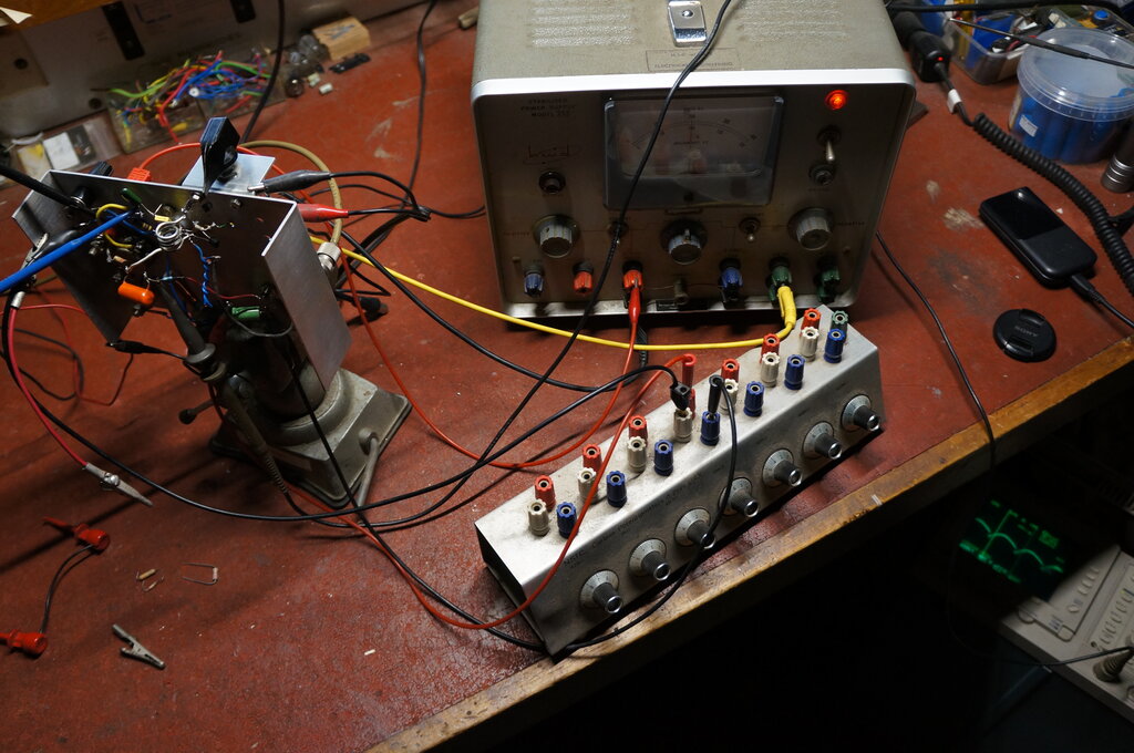
Test set-up for the receiver. This is how many of my projects begin.