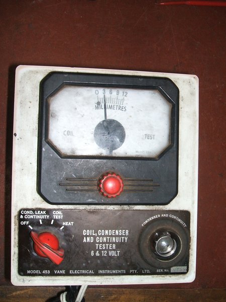
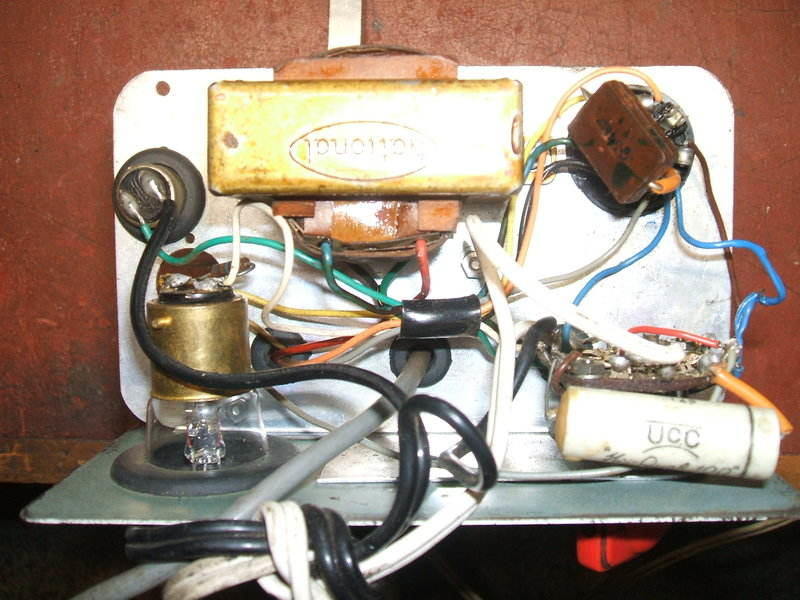
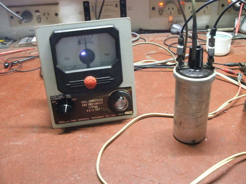
Model 453 Tester as received for repair.
Model 453 Tester as received for repair.
This unit came in for repair from an auto electrician as a result of the vibrator articles elsewhere on this site. The tester contains a V5211 split-reed synchronous vibrator which was assumed to be faulty, and I was asked if I could repair it. As will be seen further on, it was fortunate the whole tester was sent to me, and not just the vibrator.
I had not heard of Vane Electrical Instruments before, but established it was a Sydney based company. This particular tester was, according to the date stamps on several parts, made around 1962. Like other Australian made automotive test instruments of the era, there was almost a crude backyard manufacturing look about the construction, and as I discovered, the electrical design was similarly primitive.
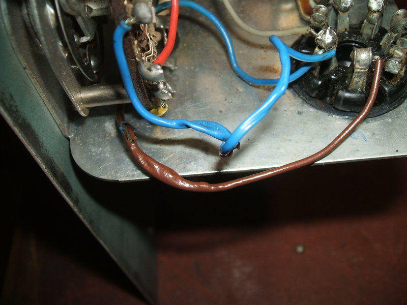
Burned wires connected to vibrator contacts.
I noted that a 16uF 450V capacitor had been replaced, and that there was a 0.047uF paper, and a 0.0047uF mica type present. The vibrator had been unplugged and wrapped separately - obviously "got at" sometime in the past. Two wires to the vibrator socket had been overheated, with melted insulation visible.
With no instructions or a circuit, it was necessary to trace out the circuit to find out what this instrument does, and how to operate it. Despite so few components, circuit tracing was made difficult by the use of random wire colours and numerous connections to the three section rotary switch. However, once done, everything became clear. I also gave the unit a good clean - it had the usual grimy appearance from being used in a mechanical workshop.
Functions of the Vane Electrical 453 Tester.
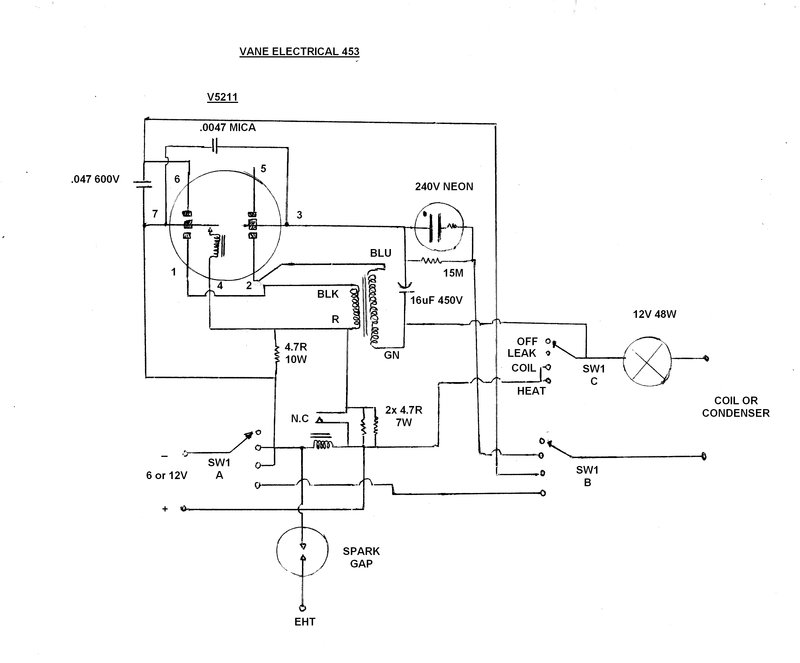
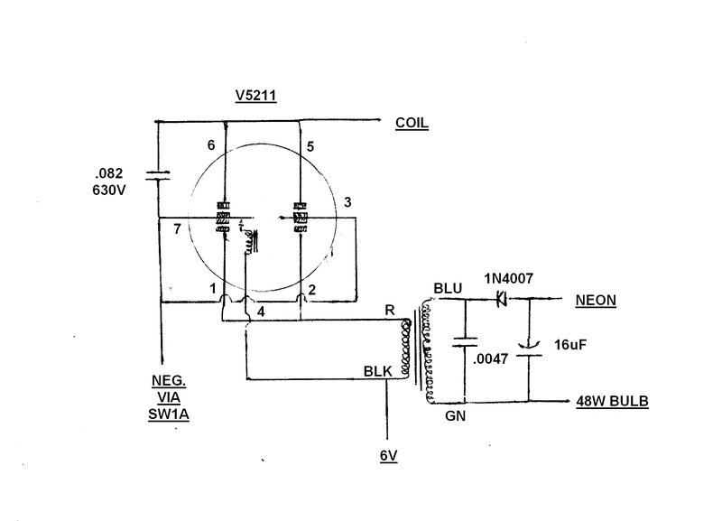
Circuit traced of the instrument in its original form. The buffer
capacitor is incorrectly connected, and the transformer incorrectly phased.
The circuit is hard to understand because
of the multiple switches, and the unconventional use of the vibrator, so
all will be explained as follows.
Three leads emerge from the instrument.
A white figure eight flex fitted with battery clips provides supply. A
black figure eight flex fitted with clips is for connection to the coil
or condenser under test, and a single grey wire with alligator clip connects
to the coil's high voltage output.
Automatic 6-12V switching.
It will be seen that there is a relay
coil across the incoming supply, with a set of normally closed contacts.
This relay actually appears to be a modified generator cut-out, with the
contacts rearranged to be normally closed instead of normally open.
When the tester is powered from 6V, the
magnetic field from the coil is not strong enough to open the contacts,
so they remain closed. However, when 12V is applied, the contacts open.
Looking at the circuit, it can be seen
there is a voltage divider consisting of two parallel 4.7R 7W resistors
across the relay contacts, and one 4.7R from here back to the negative.
So, when the contacts open, we have a voltage divider consisting of 2.35R
and 4.7R. The output of this voltage divider powers the vibrator which
is a 6V type. With the loading of the vibrator, about 6V appears at the
junction of the resistors with the input at 12V. When the input is 6V,
the supply flows directly through the N.C. contacts to the vibrator.
Unfortunately, the 4.7R 10W resistor is
always across the vibrator supply, consuming an extra 1.3A, even when operating
with a 6V input. The automatic voltage selection and vibrator circuit operate
only when the coil or leakage tests are used.
It is understandable that in the early
1960's, both 6V and 12V were in common use, so the automatic voltage changeover
circuit is a good idea, but it could have been done more efficiently. With
the low load on the vibrator, the bleed current of the voltage divider
does not need to be so high.
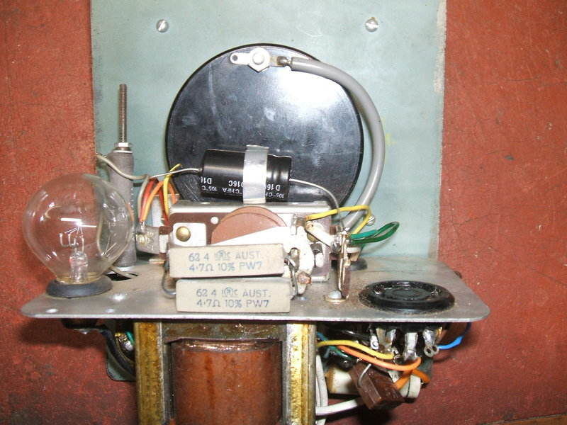
The relay and two 4.7R 7W resistors can be seen. Behind the bulb
is the 4.7R 10W resistor.
Leakage Test.
Here the vibrator operates in a half wave
DC-DC converter circuit which provides about 320V. This supply feeds a
simple neon lamp continuity tester. If the condenser (or other component,
such as a motor winding), is sufficiently leaky, the neon lamp will glow.
The transformer is a National type, but
with no number. It was established by feeding in 3V 50c/s to its primary,
that 280V was produced in the secondary. Thus, the ratio is 1:93.
Looking more closely at the circuit, pin
1 switches the primary winding to the primary reed (pin 7). Secondary reed
(pin 3) and contact at pin 2 provide synchronous rectification in the normal
way. The resultant DC is filtered by a 16uF 450V electrolytic capacitor.
Unfortunately, there is an error in construction,
and the circuit had been operating with no buffer capacitance. Note
that the 0.0047uF mica capacitor connected between the two vibrator reeds
does nothing, and there is no capacitance across the secondary of the transformer.
Indeed, when examined, there was a small
continuous arc across the vibrator's rectifier contacts connected between
pins 2 and 3.
It would appear the intention was to
have connected the 0.0047uF across pins 2 and 3. Better still would be
directly across the secondary winding. Yet again, we see careless construction
and design causing vibrator damage, and no doubt another example of "vibrators
are unreliable...".
As it is, half wave operation of vibrators
is not desirable for longest life, but in the case of a tester used intermittently
for short periods, it is tolerable. The reason for half wave operation
being implemented here is so the other set of primary contacts can be used
for ignition coil testing.
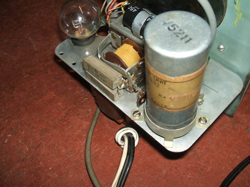
Under the chassis shows the transformer, switch, neon, and two capacitors.
A disadvantage of half wave operation and synchronous rectification is that input polarity is important. Given that the input cable is ordinary twin flex with no polarity markings, it is easy to imagine the battery clips being incorrectly fitted if the cable needs to be reterminated. The only polarity marking is a "+" on one of the battery clips. I placed a length of red heatshrink tubing over the positive wire to make it more obvious.
16uF is overkill as far as filter capacitance is concerned. The neon lamp only draws a few milliamps, and does not require a perfectly filtered supply. Furthermore, there is a slight shock hazard if the test clips are touched, if the 16uF is still charged, even though the tester is not connected to the battery. The current that flows is limited largely by the series resistor for the neon lamp, but enough to feel a shock. A smaller filter capacitor, say 0.47uF or 1uF would discharge much faster in such circumstances.
The neon lamp is an ordinary 240V pilot lamp type fitted with a B22 bayonet base and internal resistor. It is crudely mounted on the front panel with nothing more than a rubber grommet. The wires are soldered to its base. Across the neon lamp is a 15M resistor. Its purpose is to make sure the neon glows only with a specific amount of leakage in the test circuit. It will be noted that there is always a 48W lamp in series with the test leads. This has no effect during the leakage test due to the low resistance of the filament.
Coil Test.
For this test, the 6 or 12V battery supply
passes through the 48W bulb, the ignition coil primary, and then via the
vibrator contact at pin 6 to the primary reed at pin 7, and back to the
battery. Across the vibrator contacts is a 0.047uF 600V paper capacitor.
This simulates the points capacitor in a distributor, and controls the
rate of collapse of magnetic flux in the coil. It also reduces contact
arcing. Surprisingly, this capacitor is much lower than that usually fitted
to a distributor, which is usually around 0.22uF.
The 48W lamp is actually a 12V headlight
bulb with two 24W filaments. Like the neon lamp, it's mounted in a rubber
grommet on the chassis with the wires soldered to the base. Its purpose
is to limit the current and protect the vibrator and wiring if the test
clips are short circuited (or connected to a short circuited load).
The EHT output of the coil connects to an adjustable spark gap mounted on the front panel. This is built into a modified meter housing with a window to show the spark. What is normally the meter zeroing knob moves the spark gap closer or further apart, and a needle shows the distance on a calibrated scale. The earth return of the spark gap is via the negative battery lead.
Heat Test.
This is the simplest of tests and simply
connects the test leads direct to the battery via the 48W lamp. Maximum
current is therefore 4A when a 12V battery is used. The vibrator is inoperative
during this test.
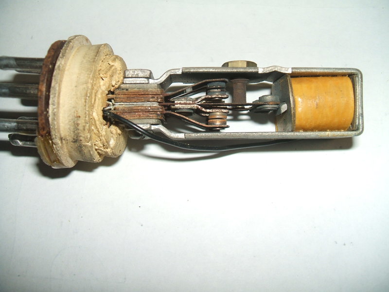
The burned contacts (upper) are the rectifier contacts (pins 2 and
3) and shows the result of no buffer capacitor. The epoxy repair the to
phenolic base can be seen at the bottom. The rubber base support was starting
to crumble.
Out of curiosity, I tried the vibrator in the Heathkit VT-1 Vibrator Tester, and it showed reasonable performance.
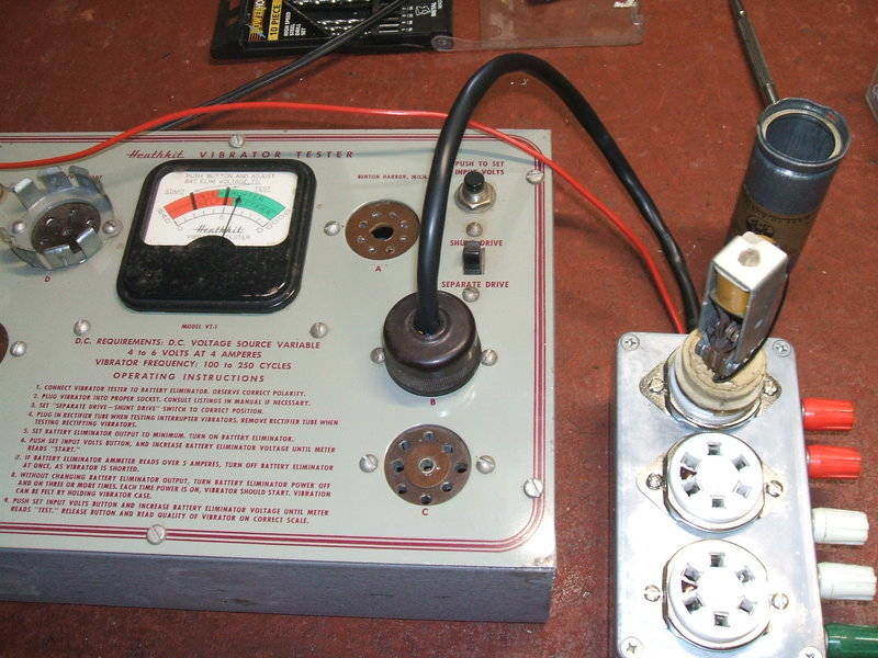
V5211 being tested in the Heathkit VT-1.
It's a curious thing why the vibrator was
attacked in this way when there was actually nothing wrong with it. It
took a little bit of work to restore it, firstly checking the contact timing
on the test panel,
and replacing the foam base support. I also had a plan to modify the circuit
to make things easier on the vibrator, and so I changed the timing of the
secondary contacts to be in time with the primary - the idea to make it
a dual-interrupter type.
The bodgie epoxy repair to the base and
the missing spring clip made things awkward. How to secure the base to
the can? I took an easy way out and used hot melt glue - strong enough,
but can be removed if need be. Oak vibrators have a heavy zinc can, and
are apt to fall out out of their socket, especially in a portable instrument
like this. What should have been done when the instrument was made, I now
did, and secured the vibrator into its socket with a capacitor clamp.
Vibrator will not fall out of socket now that it is clamped in position.
The modified cut-out relay can be seen to the left.
The 0.047uF paper capacitor between pins
6 and 7 was a UCC "Hi Qual", and as expected was leaky. Initially, I replaced
it with a 0.056uF 630V type and was surprised at the poor coil output.
It turned out this new old stock capacitor was open circuit, measuring
66pF. I then replaced it with a Philips polycarbonate 0.082uF 630V type.
The extra capacitance was felt to be an improvement, but contact sparking
is still not totally eliminated.
With the coil tester operating satisfactorily,
next thing was the DC-DC converter. A 1N4007 took place of the rectifier
contacts, and experiments were made with the buffer capacitor. The primary
waveform was most strange.
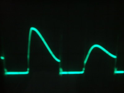
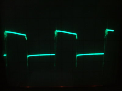
Incorrect phasing caused a bad waveform at left. Correct waveform
shown at right.
Regulation was very poor with the supply
putting out over 600V with no load! It's a wonder the 450V rated electrolytic
didn't explode. With the test leads shorted, the supply dropped to something
more normal at around 320V. This was not acceptable since the tester might
be run with nothing loading it. I thought about bleed resistors and such,
but with the waveform looking very strange, I remembered the importance
of polarity with half wave vibrator supplies.
What was happening here was the rectifier
was operating on the back EMF from the transformer - hence the very poor
regulation. I reversed the supply which not only reduced the absurdly high
no load voltage, but improved regulation significantly. Now, the rectifier
was actually rectifying the stepped up primary voltage.
Obviously, the transformer phasing was
incorrect. This, along with an incorrectly connected buffer capacitor really
makes one wonder about the quality control. Reversing the connections of
the primary winding fixed the problem. The 0.0047uF mica capacitor appeared
acceptable for the buffer and was connected across the secondary winding.
At some stage in the past, the 16uF had
been replaced with a modern type, so it stayed.
During this work, it was noticed the red
control knob was a little loose. Tightening the grub screw unfortunately
caused an existing crack to open up and the knob was now broken in half.
It was replaced with a heavy duty type that has a brass bushing to clamp
around the switch shaft.
Coil testing in operation. Note the spark gap. The red control knob
had broken in half and was replaced.
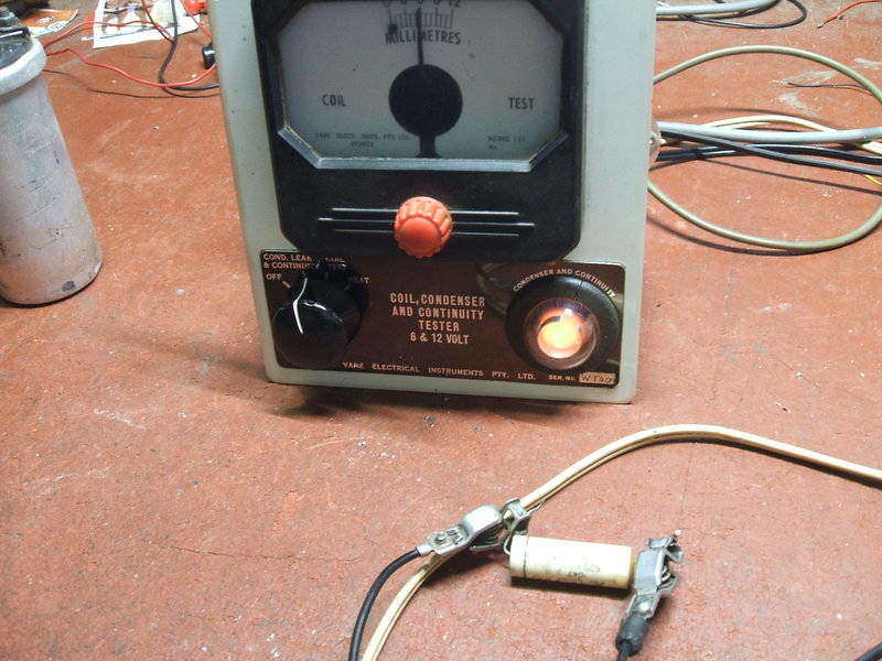
Condenser test showing leakage in the 0.047uF originally in the
tester. Leakage needs to be about 10M to cause the neon to start glowing.
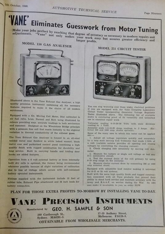
Advertisement for other Vane instruments.