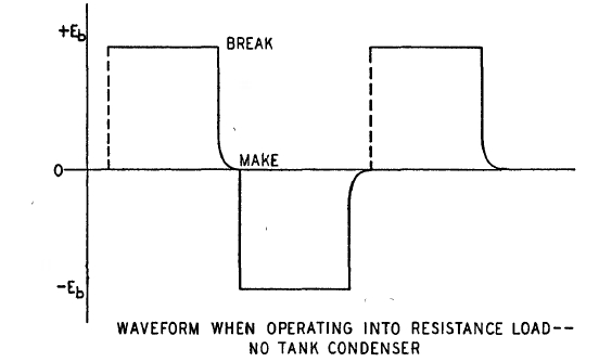
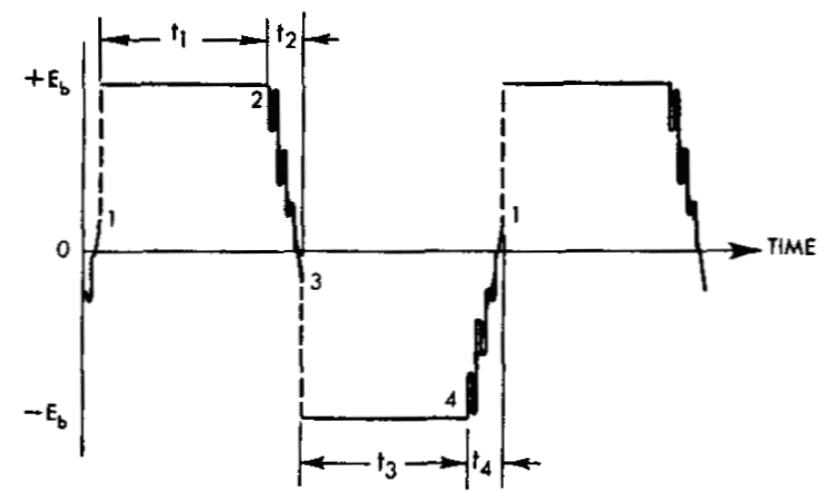
Voltage waveform of resistive load.
One of the misunderstood aspects of vibrator
power supply design is the timing circuit. Most texts refer to a so called
'buffer' capacitor, the function of which is described as to suppress high
voltages, which occur due to the inductive nature of the circuit.
The general inference is that the capacitor
prevents contact sparking, in the same manner as by placing a capacitor
across the contacts of a relay or switch. In this instance, the capacitor
reduces or prevents sparking, because it appears as a short circuit immediately
the contacts are opened. The capacitor takes time to charge, by which time
the contacts are far enough apart to prevent a spark.
As far as vibrator power supplies are concerned, not only is the operation different, but the choice of the capacitor is quite critical. Unfortunately, damage to the vibrator occurs when this is not understood, as we will see later in this article.
Timing Circuits.
If a vibrator is fed into a centre tapped
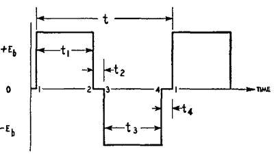
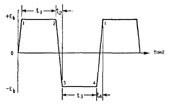
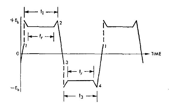
resistive load, the following waveform is produced:
Voltage waveform of resistive load.
The pull contacts close at 1, and open at 2. t1 represents the time when the pull contacts are closed. When they open, there is no current flow (t2), until the inertia contacts close at 3. t3 represents the time when the inertia contacts are closed. Similarly, when the inertia contacts open, at 4, current no longer flows at t4. A resistive load can be used for testing vibrators, because it gives a clear indication of contact timing and condition.
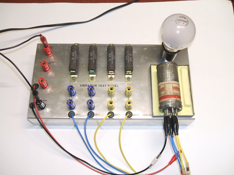
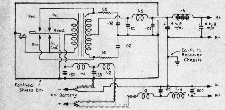
Resistive test load for vibrators.
Normally, a vibrator feeds a transformer
instead of a resistor, and here the operation becomes quite different.
Since a transformer is an inductive load,
high induced voltages would be generated at each make and break of the
contacts (t2 and t4). Apart from causing contact arcing, insulation failure
of the transformer could occur. To control these high voltages, a timing
or buffer capacitor is connected across the primary and/or secondary
of the transformer.
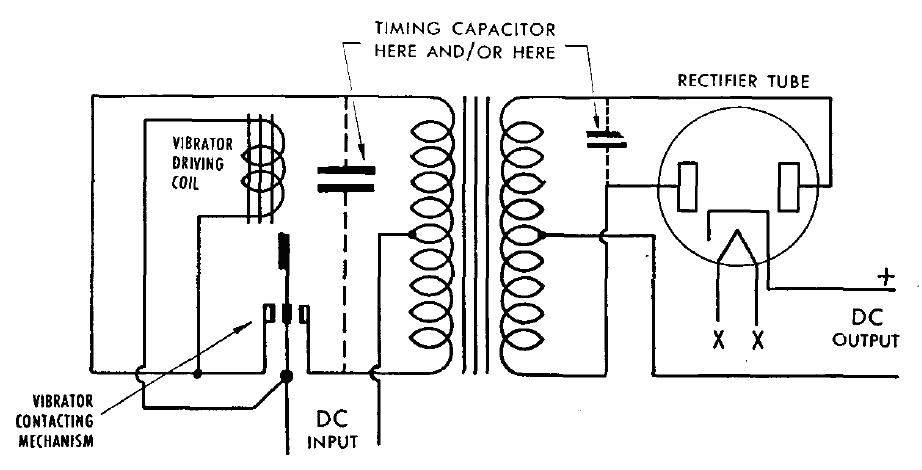
Timing capacitance is connected across one or both windings of the
transformer.
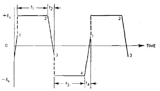
The capacitance forms a tuned circuit with the transformer inductance, which is set into oscillation at each opening of the contacts. By selecting an appropriate value of capacitor, this oscillation reverses the voltage, so that it coincides with the voltage applied to the transformer, when the opposite contacts close.
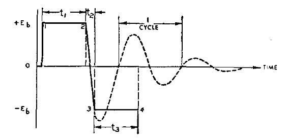
This is represented by the line from point
2 to 3. If the contacts did not close at point 3, the normal voltage decay
curve would be represented by the dotted line.
With the appropriate capacitance connected
across a winding, the following waveform is obtained:
"Ideal" vibrator waveform.
The vertical lines and discontinuities now become a slope. This is the ideal waveform.
In simple terms, the timing circuit
controls the voltage waveform, so that when the contacts make and break
there is minimal voltage across them.
The greatest electrical wear of a switch
occurs when it is making and breaking current, not when it is actually
closed. If the circuit is arranged so that the current flows only after
the contacts make, and before they open, the contacts will subjected to
minimal electrical wear. The capacitor value must be carefully chosen to
ensure this voltage reversal occurs at the correct time. Many values of
capacitance will prevent visible sparking, but only one will provide this
correct operating condition. Understanding this was one of the breakthroughs
for reliable and long life vibrator design. In the early days, timing capacitors
(or buffer capacitors as they were originally called, since the timing
function was not properly understood) were selected by trial and error
and whatever stopped the sparking. Even though sparking might not be
visible, high peak currents may be present, and contact material transfer
can take place, causing contact pitting, and eventual locking.
At first thought, it might seem that some kind of voltage limiting device across the transformer is all that's needed to suppress the high voltage transient, when the contacts open. Indeed, a few early circuits did just this with a voltage dependent resistor. However, as described above, this is not the complete answer, because there is nothing to reduce the voltage across the contacts when opening and closing. In summary, the timing circuit performs two important functions:
Practical Considerations.
Ideally, the timing capacitor is connected
across the primary winding. The value of capacitance tends to be in the
tens of microfarads for a supply operating on 6V. In the days of paper
capacitors this meant an impractically large capacitor. Electrolytic types,
while smaller, are unsuitable for continuous AC operation.
The way around the problem is to instead
place the capacitance across the secondary. The voltage step up of the
transformer also steps up the value of capacitance by the square of the
turns ratio, so a much smaller capacitor can be used.
To illustrate this, assume the timing capacitor
across the primary needs to be 20uF.
The transformer has a 6V primary and 250V
secondary. In practice this means a 12V CT primary and 500V CT secondary,
but the ratios are the same. Turns ratio is 41.7, and squared is 1739.
Now, by placing the capacitor across the secondary, it will be 1739 times
smaller; which calculates to 0.012uF.
However, now being connected across the
secondary, the capacitor has to be rated at a considerably higher voltage;
typically 1500 V when connected across a 500 V secondary. Nevertheless,
because of the low value, the capacitor remains of small physical size.
Sometimes the capacitor is placed across half the secondary, thus requiring
less of a voltage rating, and without requiring an excessively large capacitance
value.
Because of transformer leakage inductance, the reflection of capacitance from the secondary to the primary is not perfect. Some power supplies, particularly operating from 12V and above, include a portion of timing capacitance across the primary. It becomes practical at higher input voltages; e.g. 12 or 32V, to include more of the timing capacitance across the primary, since the capacitor value is reduced with an increase in supply voltage.
It is important to note that the value of timing capacitance depends on both the transformer and vibrator characteristics; in particular the operating frequency, the transformer inductance, and the vibrator duty cycle. Substitutions of any one of these components should not be made without checking the suitability of the others.
Waveforms.
The best way to determine correct timing
capacity is by observation of the primary waveform. There are several waveforms
to know:
1) Ideal Timing Capacitance.
2) Practical Timing Capacitance.
3) Insufficient Timing Capacitance.
4) Excess Timing Capacitance.
Practical Timing Capacitance.
Because a vibrator is a mechanical device,
it is subject to certain tolerances during manufacture, as well as a slight
increase in contact spacing as the vibrator ages. The timing capacitance
has to allow for this. Since the capacitance value is higher for a wider
contact spacing (i.e. a reduced duty cycle), the chosen timing capacitor
value is slightly higher than the ideal. In practice, it is selected to
obtain a 65% slope:
Practical waveform has 65% slope.
The capacitor is selected so the distance between points 2 and 3, and 4 and 1, is 65% of the total peak to peak voltage.
Insufficient Timing Capacitance.
If the timing capacitance is insufficient,
the following waveform is obtained:
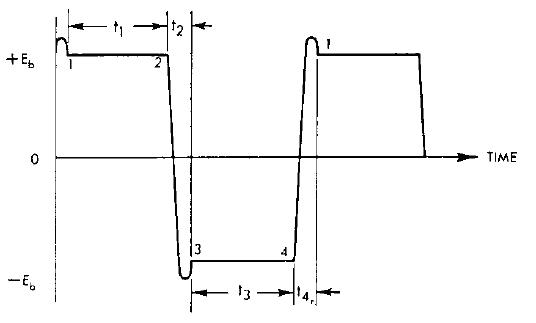
Insufficient timing capacitance.
It can be seen that the period of oscillation has reduced; i.e. increased in frequency. The peak of the first quarter cycle passes before the contacts close at 3. As such, high voltages are present, as shown by the overshoot.
Excess Timing Capacitance.
If the capacitance is too high, the period
of oscillation is increased, and reduced in frequency:
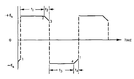
Excessive timing capacitance.
The period for voltage reversal is reduced
to much less than the needed amount.
This is undesirable because high peak
currents flow as the contacts begin to make, and causes contact material
transfer. This can eventually lock the contacts together. Furthermore,
the high transient currents can create additional RFI.
A method which has sometimes been suggested for determining correct timing capacitance, is to measure the DC supply current of the power supply, operating into no load. The timing capacitance will be ideal when the current is at minimum. In practice, the change in current is very slight over a wide percentage change in capacitance at the minimum point, so the exact value can be difficult to determine. The method should only be used if a CRO is not available.
Synchronous Vibrators.
The waveforms described thus far are for
non-synchronous vibrators operating into no load; i.e., the rectifier is
removed. Synchronous types show a slightly different waveform:
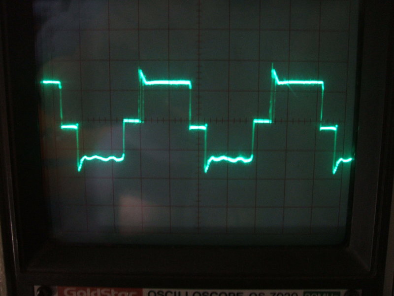
Synchronous waveform.
Unloaded, the synchronous waveform is the same as for the non-synchronous, but when loaded, it appears as above. The rectifier contact timing is shown by tr. The voltage drops for this duration, because the B+ circuit is loading the transformer at this time.
AC Inverters.
Where the load on the vibrator transformer
secondary is resistive, such as an incandescent lamp or soldering iron,
the timing circuit operates differently.
In this instance, current is being drawn
from the transformer over the entire time the voltage takes to get from
Eb to 0 . In the case of a capacitor input rectifier load, current is drawn
only towards Eb. With a resistive load, the result is that the timing capacitor
discharges much faster than it otherwise would. In other words, the load
drains the timing capacitor beyond the current it can supply. Despite the
now ineffective timing capacitance, the creation of high voltages are instead
prevented by the load. However, the disadvantage with this mode of operation
is that the full voltage is across the contacts when they make. The timing
capacitor still functions normally with no load, but becomes less effective
as the load is increased.
This condition is detrimental to the operation,
as compared to a capacitor input rectifier load. The condition is worsened
if the load is inductive. In practice, where the load is resistive, vibrator
life is usually satisfactory. If, of course, the inverter is powering a
device with a rectifier at its input, the timing capacitor will function
normally - assuming there is no extra capacitance (such as AC filtering)
in the input circuit of the powered device.
Some inverters include a higher than normal
timing capacitor value, in an attempt to control the voltage reversal whilst
loaded. Obviously, the timing capacitance is excessive when unloaded, and
a warning is usually given to avoid such operation.
In the case of the Browning Porta-Lamp, there is no timing capacitor. This may seem undesirable at first, but a closer look at the operating conditions shows it is not as bad as it looks. Importantly, the load is a fluorescent tube. During starting, the load is resistive as the inverter is loaded by the tube filaments. This in itself is sufficient to prevent damaging peak voltages. Once the tube has started, no current is drawn on the voltage waveform until the voltage across the tube reaches ionisation voltage. Again, damaging peak voltages are similarly limited by this voltage. If the tube is not ionised however, high peak voltages are produced, so it is important not to let the lamp run without the tube started.
Vibrator waveform for Browning Porta-Lamp.
In this application, the fluorescent tube
presents a roughly similar type of load as a capacitor input rectifier.
That is, no current is drawn until towards the top of the voltage cycle.
In this regard, it was felt that a timing capacitor would be beneficial
to vibrator life.
A suitable value was determined and connected
across the transformer primary.
Another instance where it seems that one can get away with no timing capacitor is with certain transformers, which usually have a higher than normal turns per volt ratio. However, no sparking on the contacts does not necessarily mean all is well, since there is nothing to prevent current flow during contact opening and closing, and thus material contact transfer.
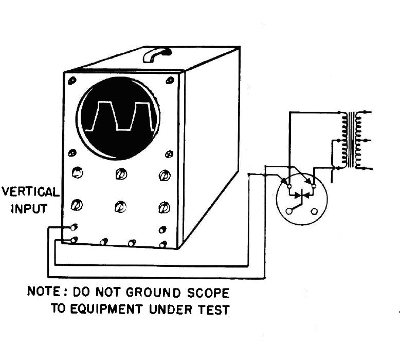
The waveform should be measured across the full primary, since this is what the vibrator sees. It is important that the power supply for the vibrator must be isolated from earth for this measurement, since one side of the CRO input is earthed, which would otherwise cause a short circuit. The obvious exception is if the CRO is battery operated or otherwise isolated. It is also possible to use a dual trace CRO in differential mode, to provide for both inputs to be floating.
Resistors.
Resistors are often used in the primary
circuit, either connected across the primary winding, or across the vibrator
contacts. These reduce RFI by damping the voltage overshoot when the contacts
open. As such, they can also lengthen contact life. Values are typically
50 to 500 ohms, depending on supply voltage.
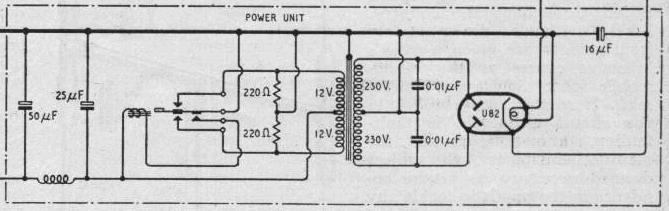
220R resistors damp transformer
primary.
In some timing circuits, a resistor of typically 5k to 15k is connected in series with the capacitor (R21, 15k, in the circuit below).
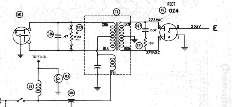
R21 damps leakage inductance oscillations.
Not a Fuse.
Unfortunately, many texts erroneously
assume this resistor acts as a fuse in case the capacitor shorts. This
is a strange theory, because it means the power supply is then left operating
with no timing capacitance, which unbeknown to the user is quickly ruining
the vibrator. Most such articles have been compiled by trade level servicemen,
unfamiliar with the true operation of a vibrator power supply. Not understanding
the finer points of transformer design, the 'fuse' theory is the simplest
explanation.
It goes without saying that the supply
should be fused to protect against capacitor failure.
In actual fact, as Mallory
literature explains, the resistor is to damp oscillations caused by
transformer leakage inductance.
Periods t2 and t4 show oscillations caused by transformer leakage inductance.
Synchronous Vibrators.
In synchronous circuits, where the timing
capacitance consists of two separate capacitors, resistors should be included
where the rectifier contacts short circuit the capacitors. Typically 50
to 200 ohms, these resistors limit the capacitor discharge current when
the contacts close. The fully charged capacitors would otherwise be short
circuited directly, which is not only hard on the capacitors, but increases
the possibility of sparking, and subsequent contact wear and RFI.
50R resistors limit timing capacitor discharge current.
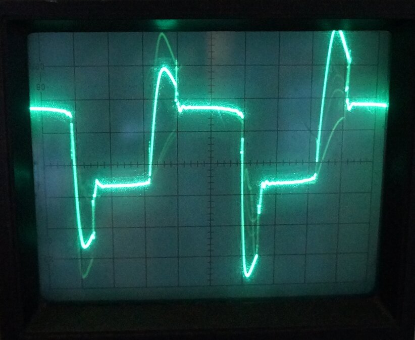
Grossly insufficient timing capacitance!
As can be seen, there is no slope to the waveform, and the peak voltages are excessive.
Restoration Gone Wrong.
I had noted the circuit diagram specified
a 0.01uF timing capacitor. In the set was instead 0.0082uF. The capacitor
fitted was a 2kV polypropylene type, which was correct as far as that is
concerned, but the value was too low. My guess is the restorer thought
0.0082uF was 'near enough', since it's only one preferred value down from
0.01uF. It so happens that 0.0082uF is the standard value for most Astor
car radios, and given that these are the most common car radio in Australia,
and that the restorer specialised in car radios, it's likely that he had
an ample supply of these.
Note the arcing on the left side contacts - a result of incorrect
timing capacitance, and the substitution of a lower frequency vibrator.
It just goes to show, that near enough
is not good enough when it comes to timing circuits. If one
absolutely must use the wrong value, use the next one up,
not the next one down. A higher value is preferable, if there is no choice.
Sadly, the vibrator had been damaged.
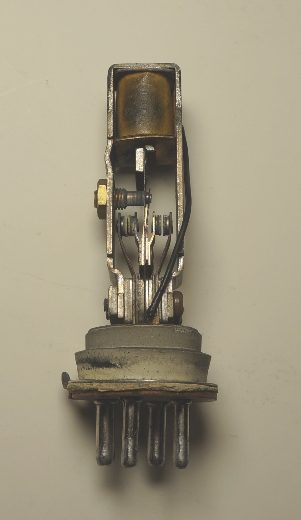
Damaged vibrator. Note the wear on the pull (right side) contacts
and the black deposits of contact material.
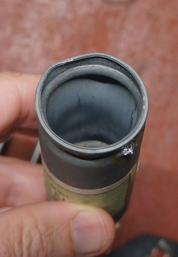
Contact material deposited inside of can.
Clearly, the contacts had been burned, with the pull set having a noticeably increased gap. The stack had also run very hot, as evident by the condition of the black PVC drive coil wire, where it runs alongside. And of course, there was contact material deposited on the internal parts and the inside of the can. The Oak V5123 vibrator had been installed as part of the restoration.
Once the set warms up with the low timing capacitance, the peak
voltages disappear. Note the uneven duty cycle because the pull contacts
have excess spacing.
The only saving grace was that once the set had warmed up, is that the loading of the B+ circuit suppressed the high peak voltage. However, the damage was being done every time the set was switched on from cold, but ultimately without the timing circuit working, contact material transfer would still be taking place after warm up. First thing to do was replace the 0.0082uF with a 0.01uF. This immediately calmed down the vibrator and eliminated the high peak voltages.
Interestingly, the remains of the original
vibrator were found in a bag of original parts which the owner provided.
Strangely, only the mechanism was present. My guess is the restorer kept
the can and base to stuff a solid state replacement into for another job.
The vibrator manufacturer is unknown,
but looks as though there's a Mallory influence in its design. After cleaning
the oxide off the contacts, it started straight away. In fact the contacts
looked in very good clean condition, and provided an 'as new' waveform,
with absolutely no sparking. Not only that, it started at 9V, which indicated
it had a lot of life left before adjustment would be required. It's a puzzle
why the restorer didn't even bother to clean the contacts and use it. The
point is, that since it was in such good condition, it proves that the
original timing capacitor was the correct value.
Original vibrator is almost as new. Why wasn't it used?
Frequency.
There's another factor our restorer overlooked.
The original vibrator was measured at 120Hz. (It would have had a design
centre of 115Hz). However, the Oak which substituted it measured 103Hz
(design centre 100Hz). This in itself meant that the timing capacitor was
already getting to be a bit on the low side, since timing capacitance is
influenced by frequency and duty cycle. Generally, as frequency and/or
duty cycle is decreased, the timing capacitor needs to be increased. So,
when you substitute a vibrator with lower frequency and a
timing capacitor of lower capacitance, the effect is worsened even more.
With the Oak cleaned up and the contacts
adjusted, the 0.01uF timing capacitor was only just adequate. It's no wonder
that with 0.0082uF the vibrator was damaged.