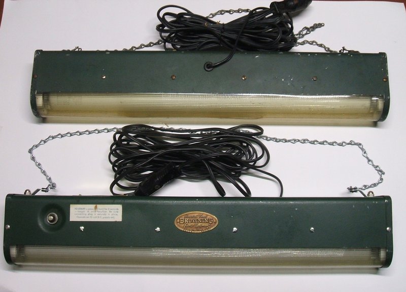
First two Porta-Lamps in my collection.
First two Porta-Lamps in my collection.
Fluorescent lamps have always interested me, especially those operating from power sources other than mains AC. When I discovered that there had been a model available in the 1960's with a vibrator inverter, I had to have one. And, so to the subject of this article.
A quick guide to portable fluorescent
lamps.
Conventional fluorescent tubes as we know
them have only existed since 1939. These are the conventional bi-pin end
tubes usually used with a glow tube starter, and run from an AC mains supply
through a choke to limit the current. The most common types would be 20W
and 40W in the T12 size. T12 refers to eighths of inch diameter. So, a
T12 tube has a diameter of 1.5". These are now considered obsolete, being
replaced by 18W and 36W T8 tubes. Once common in desk lamps, and still
used in aquarium lights is a 15W T8 size. Smaller tubes, 13W, 8W, 6W,and
4W of T5 size were used in some small mains powered light fittings, but
were the mainstay of fluorescent torches and caravan / boat type lamps
operating off 12V DC.
Generally, most fluorescent torches use
6W or 4W tubes. Before solid state inverters appeared, a fluorescent torch
used high voltage batteries of the radio B battery type (90V) to power
the flourescent tube. A resistive ballast has to be used to limit the tube
current, as the battery supply is DC. A manual preheat starting switch
is used as the supply is insufficient for a glow tube starter.
Perhaps the most well known of this type
is the 8W Burgess Safari Lite which uses two 69V batteries and was made
until the early 1970's.
In the 1960's efficiency and economy of
operation improved with the advent of transistor inverters to drive the
tube. It meant a fluorescent torch could be operated off, say, four to
eight C or D cells, instead of expensive B batteries. Such torches often
incorporate an external 12V input for running from a car cigarette lighter.
Invariably, the design of such torches
is based around a one transistor oscillator driving a ferrite cored transformer
to provide the high voltage to drive the tube. The leakage reactance of
the transformer provides current limiting once the tube has ionised. Unfortunately,
many designs omit any filament preheating, instead relying on sufficiently
high voltage to force the tube to ionise. This strips the cathodes during
starting, causing short tube life in these torches. The asymetrical waveform
also creates a DC component, resulting in one cathode wearing faster than
the other. This aspect, however, can be remedied by reversing the tube
every so often.
As well, these torches rarely operate
the tube at its full current, which is why a mains powered fluorescent
tube of the same wattage is usually brighter. To a large degree this is
done for battery economy.
For example, a 6W tube would, allowing
for inverter efficiency, probably require about 8W, to get mains brightness
from a 12V battery. 8W at 12V is 750mA - a very tall order to place on
a set of D cells, or even a pair of 409 lantern batteries, when any kind
of reasonable life is to be expected.
However, with cost often being the main
selling point, these simple circuits have remained popular until the present
time, at which point portable fluorescent lighting is rapidly being replaced
by LED's.
Better circuits use a full wave inverter
with two transistors, preheat the filaments, and some use a separate capacitor
or choke for current limiting rather than rely on transformer characteristics.
There was however, a period where vibrators
were used for the inverter, when larger tubes such as 20W were to be driven
from a car or other lead acid battery. The Australian inverter manufacturer,
Glenradio, made a 20W caravan lamp in the 1950's. Radio & Hobbies in
1952 described construction of a 40W (or twin 20W) fluorescent lamp operating
from a 12V battery for use in blackouts.
The chances of finding one of the Glenradio
lamps would be virtually impossible given the small quanity ever made.
I had seen one advertised on ebay a couple of years ago, but you had to
buy the whole caravan to get it!
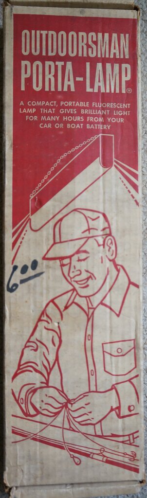
More recently, I discovered a relatively
commonly available 15W 12V vibrator powered fluorescent lamp made in the
U.S., from the unlikely manufacturer name of Browning. They appear on ebay
from time to time, and after waiting a year, I got one for the unbeatable
price of $9.99. Of course, with the postage and poor exchange rate, the
real cost was getting towards ten times that. Some months later, another
one appeared. It also went cheap - probably because it was listed in the
"Men's hats" section of ebay, and few would have seen it.
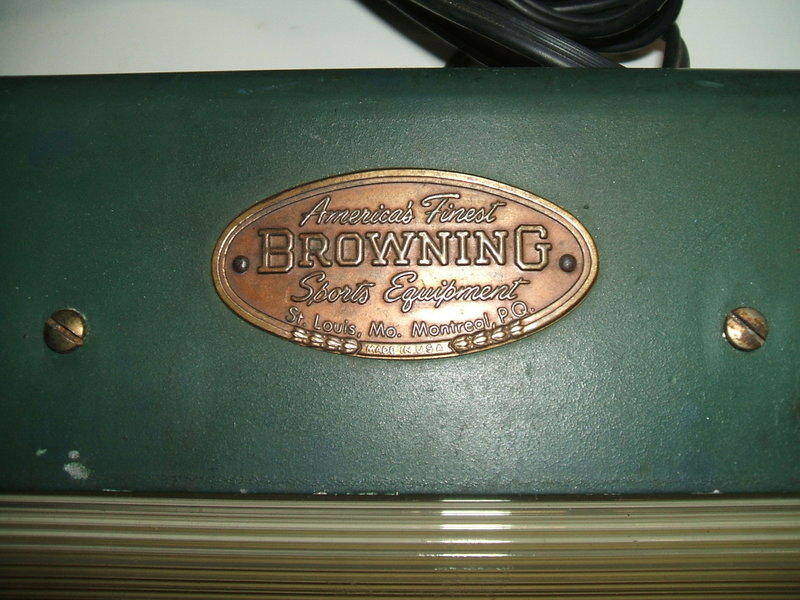
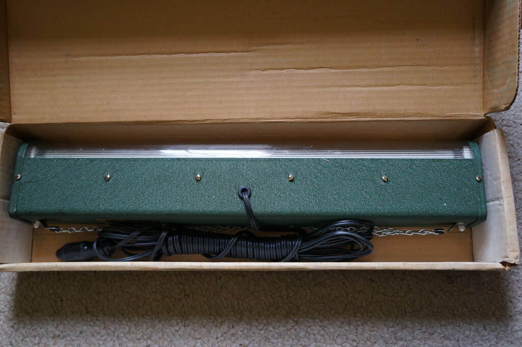
The Browning Porta-Lamp.
The first lamp, as I received it, had
obviously had a lot of use, with the lens plastic slightly yellowed from
hours of UV light, and the housing had seen a bit of wear and tear. It
worked perfectly, however. The second lamp was in much better cosmetic
condition with a clear lens and not much wear on the casing. Its labels
were also in better condition.
Of course the electrical design was of
considerable interest, with the idea of perhaps duplicating it.
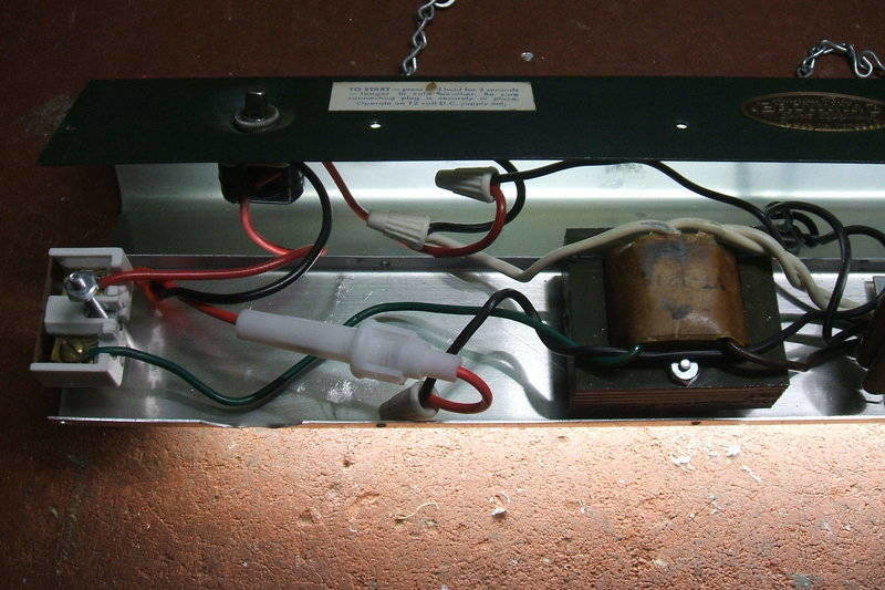
Inside the lamp it's very basic and harder
to imagine a more simple design.
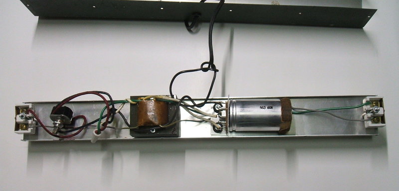
Essentially, the 12V DC is fed into a step
up transformer via a vibrator to power the T8 15W tube. The power switch
also functions as a preheat switch to start the tube. The absence of a
buffer capacitor for the vibrator was interesting, but more about that
later. Obviously, the design of the transformer was such to provide the
necessary current limiting once the tube had ionised.
At this point, for those not familiar
with vibrator power supplies, I have covered the subject extensively in
a section that can be found on my home
page, to help understand the operation.
It took only a couple of minutes to trace
out the circuit, and it was all quite conventional. The only thing that
did surprise me is that I had assumed the 12V supply might have been used
to preheat the filaments. In actual fact, it's a conventional starting
circuit using essentially the short circuit current of the transformer
secondary to heat the filaments.
One could envisage a glow tube starter
therefore, instead of the manual switch, but as I discovered the secondary
open circuit voltage was not high enough for even an FS2 starter glow tube
to ionise.
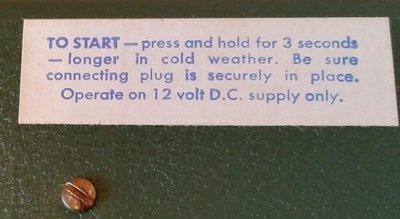
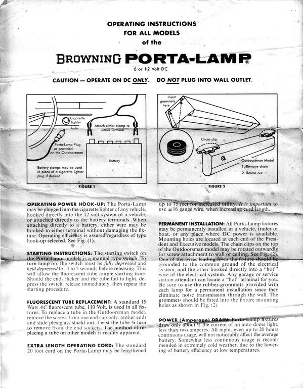
Starting instructions.
The vibrator is one made by James - a company
once famed for their "push-pull" design. This design was obsolete by the
time the Porta-Lamp came into being. I could see it was a shunt drive type,
given only three connections. A description of shunt drive vibrators is
given here.
It started without any problems, and from
the CRO patterns, the contacts are in excellent condition. This was quite
interesting, given the amount of time this lamp appears to have been run
for. Browning has evidently got the transformer design right, and used
a well designed vibrator. Clearly, vibrator life is not
something to worry about with the Porta-Lamp.
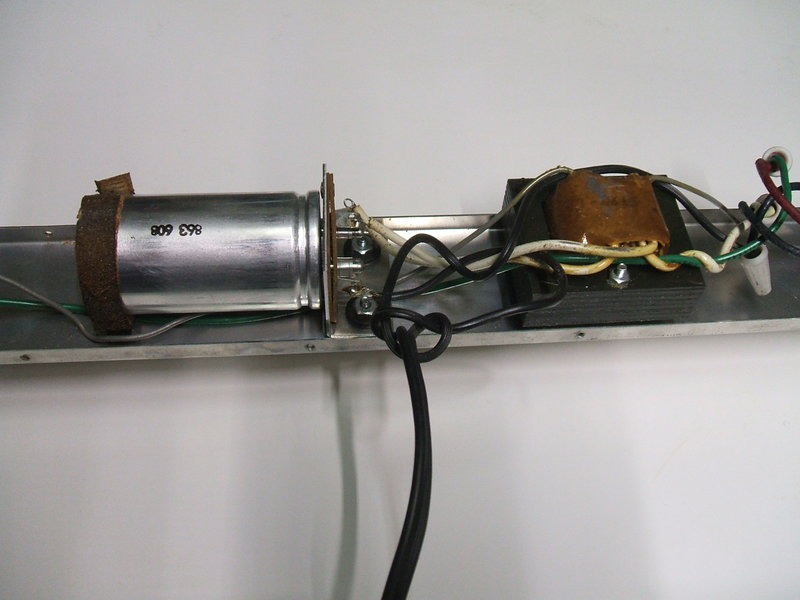
Just a vibrator and transformer. So much more simple than a transistor
circuit, and does not care about input polarity.
The Circuit.
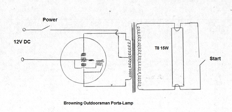
This is the simplest practical circuit for operating a fluorescent
tube from a 12V battery.
The inverter uses a conventional 12V car
radio vibrator and a step up transformer. Measured frequency was 114 c/s
before starting and 109 c/s once the tube was ionised. The slight variation
in frequency is unimportant, but would be due to the use of a shunt driven
vibrator and the loading effects.
The power and starting switch are in the
same assembly. It is of a type specifically designed for manually started
fluorescent lights. It appears to be of the type where each press of the
button moves a disc around 180 degrees. The disc is such that in one position
contact is made, and in the other it is not. Pressing the button further
down actuates the second, momentary switch for starting.
In operation, the power switch is activated causing the 12V to flow through the transformer primary and into the vibrator. The vibrator driving coil attracts the reed towards it, thus causing one set of contacts to make, short circuiting the coil and causing the reed to spring back to the other set of contacts. The alternate switching of 12V DC into each half of the transformer primary sets up an alternating magnetic field in the usual way.
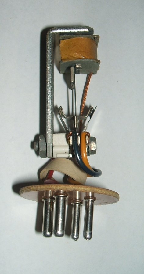
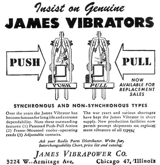
Inside the James vibrator. At right is an advertisement for an earlier
type.
Approximately 100V appears across the transformer secondary, which is applied to the fluorescent tube. This is insufficient to ionise the tube unless the filaments are heated. The switch is pressed further in, for a few seconds, causing the transformer secondary current to flow through both filaments which are now connected in series. There is now about 12V across each filament. With the cathodes now hot, the switch is released, and the 100V AC ionises the tube. Once the arc has struck, the voltage falls to about 55V, and the tube emits light until the power is turned off. Current draw from the 12V DC supply is about 1.4A.
However, to fully understand the operation, there's two things that need to be understood.
Driving a Fluorescent Tube.
A fluorescent tube has a negative resistance
characteristic. That is to say, the more current put through it, the lower
the voltage drop across it will be. This is the opposite to a normal resistive
load, such as an incandescent lamp. The reason for this is that a fluorescent
tube is, in very simple terms, an arc lamp, and once the mercury vapour
ionises it becomes very low resistance. If a tube is connected directly
across a supply, it will draw a very high current which in turn causes
the voltage drop to go even lower, causing an even greater current flow.
This snowballing effect continues until the tube self destructs.
What this means is that the current must be limited. The specifications for a 15W fluorescent tube is an arc voltage of 56V and a current of 300mA. An obvious way to limit the current is to use a resistor in series with the supply. A well known resistive ballast light fitting is the Mazda Netaline, common in the UK in the 1960's. An incandescent lamp can also be used with greater efficiency, as some of its heat is converted to light, adding to that of the fluorescent tube. The most efficient method, and the most common, is to use the reactance of a choke, where the supply is AC. One may wonder about using a capacitor to limit the current on AC supplies, but this is only satisfactory at high frequencies. At ordinary mains frequencies, a capacitor distorts the waveform, causing high peak currents which damage the cathodes. For operating stability, the open circuit supply voltage should be at least twice that of the voltage drop across the tube.
However, to get the tube to ionise (or arc) in the first place, it is depending on the tube design, necessary to provide a starting circuit. With some tubes, particularly 10W, 15W, and the T12 sizes, 20W, 40W, and 65W, the 240V AC mains voltage is sufficient to ionise the tube, but the cathodes need to be heated first to emit sufficient electrons. It is true that some of the tube sizes mentioned will often start with the cathodes not heated, but this strips the cathode and the tube has a short life if used this way. The "rapid start" circuit heats the cathodes with a transformer for starting. The "preheat" circuit uses a starter (whether it be a manual switch, glow tube, or thermal starter) to cause current to flow through the cathodes. When the starter opens and tube has ionised, the operating current keeps the cathodes hot.
Many tubes require a voltage much higher than the mains to ionise, and here the choke provides an inductive kick when the starter switch opens. The voltage of the inductive kick added to the mains voltage will start the tube.
In the case of the Porta-Lamp, the 100V AC supply is sufficient to start a 15W T8 fluorescent tube once the cathodes have been heated.
The Transformer.
Now, looking at the circuit, one may wonder
where the current limiting device is. 100V fed into a 15W fluorescent tube
would destroy it immediately. In actual fact, there is current limiting
but it's part of the transformer design. A transformer can be designed
to have high leakage reactance. That is, in simple terms, to say that the
coupling between the primary and secondary coils is made quite loose.
So, while the turns ratio determines the
secondary voltage, the coupling will determine the maximum current that
can be drawn.
While I haven't pulled apart the transformer
for examination, from what is visible from the outside, the leakage reactance
has been provided for by including air gaps between the laminations.
The result is the secondary voltage falls
to about 24V during starting with the heavy loading of the filaments, and
around 55V with the tube ionised.
I also tested the transformer with a 240V
100W incandescent bulb across the secondary. The primary current remained
the same at 1.4A, and the secondary voltage was 52V.
The transformer in one of the lamps was
stamped "VT1215", which would obviously mean "vibrator transformer 12V
15W". This makes me wonder if Browning made DC fluorescent lamps for other
voltages and wattages.
It's not just this circuit that uses a leakage reactance transformer, but 32V AC fluorescent lead lights use the same method. In places with 120V mains, a leakage transformer type ballast is often used with tube sizes above 20W.
The alternative is to use a conventional step up transformer and separate choke, but combining the function of both is more compact and elegant, and probably more efficient - not having the extra winding resistance of a choke in circuit.
Operating Characteristics.
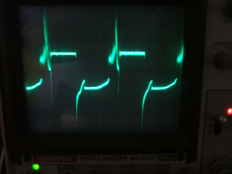
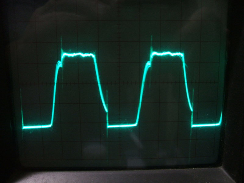
Unloaded secondary voltage; i.e. tube not ionised. Note the spiky
waveform.
As can be seen from the waveform above, prior to the tube starting, the no load secondary waveform looks awful. As well as the square wave, there are much high voltage spikes at the leading and trailing edges. These spikes come about because of the rapid make and break of the vibrator contacts in an inductive circuit. This is normally not desirable, but I'll get to that shortly.
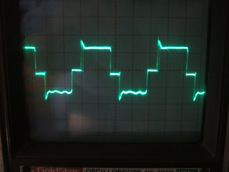
Waveform across tube once started.
With the tube started (i.e. ionised), the voltage falls and the waveform improves somewhat. The peak to peak value is now limited by the tube's arc voltage. This also clips those high voltage spikes in the previous waveform.
Timing (Buffer) Capacitor.
To those familiar with vibrator power
supplies, the question must have been asked by now, "Where is the buffer
capacitor?" Well, there isn't one in the original design. Before anyone
thinks of high voltage spikes, damaged transformer insulation, and burnt
vibrator contacts, in this application it isn't actually as bad as that.
In my experience designing vibrator power
supplies, I have found that in certain circumstances the lack of a buffer
capacitor won't result in constantly arcing contacts. It depends a lot
on transformer characteristics, and the kind of load. Generally, I found
that transformers with a lot of inductance, or a high turns per volt ratio,
will run with a vibrator with minimal contact arcing, even with no buffer
capacitor.
With the Porta-Lamp, the normal operation
is such that the fluorescent tube clamps the high voltage spikes, and this
is reflected back to the transformer primary. So, they can get away with
it here.
However, when the lamp is turned on and
not started, the transformer is unloaded and high voltage spikes do appear,
as shown previously. One could argue that these spikes help the tube ionise,
but in reality, a 15W tube doesn't need them to start. Therefore, the tube
should be started immediately in the interest of vibrator life.
In short, while they can get away with
it, it is not good design practice, so I set about experimenting with a
timing capacitor.
Adding a buffer capacitor has improved the unloaded waveform.
On the basis of minimal current draw in the unloaded (non started) state, I found that 3uF was the ideal value, connected across the transformer primary. The no load current dropped from 700mA to 200mA, and it is now a text book vibrator waveform. Thus, the lamp can be run indefinitely without the tube being started, and no harm will result. I found that with the high voltage spikes gone, there was absolutely no problems starting the tube.
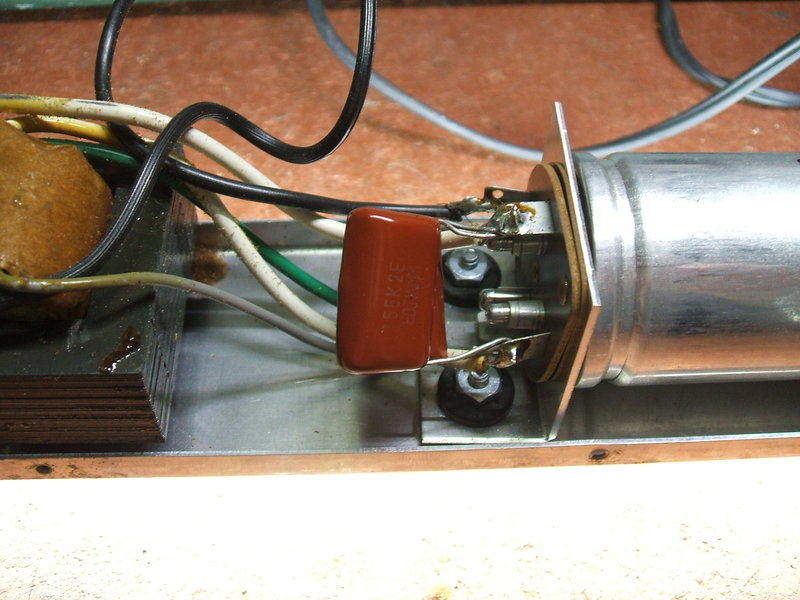
The timing capacitance consists of two 1.5uF's in parallel (3uF)
and is connected across the primary.
While the convention is to usually connect
the timing capacitance across the transformer secondary, this is done so
the capacitor could be smaller in value than if connected across the primary.
However, these days with smaller capacitors
and high values commonplace, primary connection is satisfactory, and is
theoretically better since the coupling between the windings does not affect
the reflected capacitance. I used two paralleled 1.5uF 250V polyester capacitors
connected at the vibrator socket.
In this application, a secondary timing
capacitance would be unsuitable because of the loose coupling between primary
and secondary. The capacitance would not be properly reflected back to
the primary, and the reflected capacitance would change when the tube ionised
and the secondary voltage dropped.
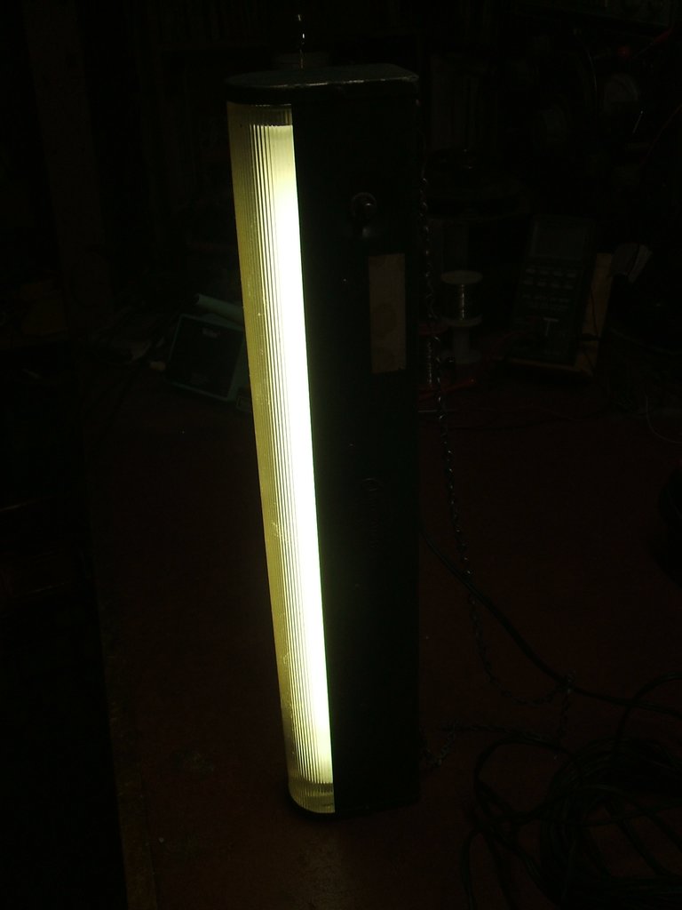
Although not so obvious here, the Porta-Lamp provides genuine mains
brightness from its 15W fluorescent tube.
Finally, I did actually check the operation
of the lamp with an open Oak
vibrator I use for the purpose. It operates at 104 c/s, so is compatible
with this circuit. There was minimal contact sparking with no buffer capacitor
present with the tube running, but more sparking was visible with the tube
not ionised. It was certainly not the destructive arcing that destroys
vibrators quickly, but more of a light sparking every so often.
With the buffer capacitor present, no
sparking at all was visible.
So, to anyone who owns one of these lamps,
the addition of a buffer capacitor is recommended. The value should be
determined for the individual vibrator depending on its duty cycle - this
being slightly variable due to wear or manufacturing tolerances.
Performance.
The Porta-Lamp provides the same brightness
as does a 15W fluorescent tube in a mains powered lamp. The vibrator buzz
is surprisingly quiet. In fact, it is probably the quietest vibrator powered
appliance I have. The supply voltage at which the lamp drops out of ionisation
is around 10.8V, so there isn't a lot of leeway with a flat battery.
The connecting cable is surprisingly long.
I didn't measure it, but the instructions state it to be 20 ft. The end
is terminated in a rivetted together cigarette lighter plug with crimped
connections. There is no fuse, which I think is one undesirable aspect
of design, but presumably the designer is relying on the cigarette lighter
being fused. The instructions do mention direct battery connection by clips,
and there will be definitely no fusing then.
An inline 5A fuse was installed in both lamps for protecting the
vibrator and transformer in case of fault conditions.
Given that the vibrator loading is not
very much, and now with the timing capacitor in place, I consider that
vibrator life should be very long and a non issue. If it ever had to be
replaced, it would be important to use one operating at the same frequency
in view of the transformer characteristics.
There is no RF filtering, and with the
lamp near an AM radio, interference can be heard. One could improve on
this, but it would be wise to use non polarised capacitors as the lamp
is not polarity conscious with the supply.
First thing was to check the vibrator was
as good as I thought it was. Well, it wasn't quite so. It would not start
until around 10V and that was only with a sudden application of voltage.
This is a limitation of shunt drive types. Even if the contact spacing
has increased slightly without affecting the output significantly, it will
affect the starting characteristics.
I tried the Porta-Lamp with two N.O.S.
Mallory G850's and a N.O.S. Wearite. The Mallorys started at below 6V.
These would show how the lamp worked when new with maximum duty cycle from
the vibrator. There was some improvement, but even at 11.5V performance
was barely acceptable.
Next, the James vibrator was opened and
contacts adjusted for proper starting; this it now did at around 8V with
a gradual increase in voltage. The contacts incidentally were in excellent
condition, and presumably it was just the hammering that had increased
the gap slightly.
Of course, now with a slightly higher
duty cycle, the 3uF buffer was a little too much. I removed one of the
1.5uF's, and the remaining 1.5uF was satisfactory.
It's important to mention that the original
vibrator would have been fine in a radio for a very long time as it was.
The duty cycle before adjustment was at 80% which is still very good, and
for some types such as the Oak, is as good as new. The critical nature
apparent here comes about because the transformer did not have enough reserve
of output in its design, and the characteristics of a fluorescent tube
being an awkard load.
The problem with low supply voltage seemed
to be that not enough current flowed through the tube to keep it ionised,
even though the open circuit voltage was sufficient for a 15W tube. Heating
the filaments separately would fix the problem, but the alterations required
would be considerable. One could put filament windings on the existing
transformer for example.
The simplest way out of the problem would
be to increase the output voltage from the transformer, so that sufficent
tube current flowed to heat the filaments sufficiently during normal running,
and hope that the inherent current limiting was still sufficient when the
battery voltage was up around 13.5V. An easy way to do this is to connect
the secondary in series with one half of the primary (adding 12V), or if
necessary across the entire primary, adding 24V to the secondary voltage.
Of course, the phasing is important or
the voltage will be reduced instead of increased. Results were looking
good with just half the secondary in series. The lamp now worked down to
at least 10.5V, and could be started at that voltage. The method of connecting
the primary in series with the secondary is explained further below.
Looking at the Philips data for a 15W tube,
the arc voltage is 54V and the current is 330mA. That actually calculates
to an input power of 17.8W into the tube, so as long as this wasn't exceeded
there should not be a problem with the modification.
Measurements were made for operating conditions
with the original wiring, and then with the modification. A true rms meter
was used since the waveforms are non sinusoidal.
Original Characteristics:
| Input Volts | Input Current | Tube Volts | Tube Amps | Tube Power | Filament Start |
| 10.5 | 200mA | 73 | 0 | 0 | 10V @ 370mA |
| 11 | 400mA | 70 | 30mA | 2.1W | |
| 11.5 | 1A | 62 | 80mA | 5W | |
| 12 | 1.4A | 58 | 170mA | 9.9W | 12.1V @ 420mA |
| 12.5 | 1.6A | 57 | 217mA | 12.4W | |
| 13 | 1.8A | 56.4 | 257mA | 14.5W | |
| 13.5 | 2A | 55 | 300mA | 16.5W | 12.8V @ 500mA |
Modified Characteristics:
| Input Volts | Input Current | Tube Volts | Tube Amps | Tube Power | Filament Start |
| 10.5 | 1.1A | 72.5 | 110mA | 8W | 10.8V @ 380mA |
| 11 | 1.5A | 60 | 173mA | 10.3W | |
| 11.5 | 1.8A | 55.7 | 217mA | 12 | |
| 12 | 2A | 53 | 260mA | 13.8W | 12V @ 450mA |
| 12.5 | 2.2A | 51.6 | 300mA | 15.5W | |
| 13 | 2.4A | 50.5 | 330mA | 16.7W | |
| 13.5 | 2.7A | 50 | 360mA | 18W | 14V @ 510mA |
The filament voltage was also checked during starting to see it was not excessive. As can be seen, in its original form, proper tube operation requires an input of at least 13V. At 12V the lamp is being fed with a little over half power. So, we can see if the lamp is operated off a battery which is not being charged, nothing like full output is obtained. At 11.5V, a not unreasonable input with the battery discharging, tube power is only 5W. Incidentally, the tabulated tube voltages and currents illustrate clearly the negative resistance characteristics.
The improvement with the modified circuit is evident. Using the Philips data for the tube, we don't have to worry about tube overload until above around 13.5V. Usable light is produced even at 10.5V, a figure of a well discharged battery - in fact so discharged the battery will be damaged.
For some time I have contemplated building
a 12V, vibrator powered, fluorescent lamp using a similar method to the
Browning. Of course, a modern 240V transformer would have to be used. The
question is, what sort? I have known since my very early inverter days,
that if the transformer has an unusually large number of turns per volt
when compared to the supply voltage it is used at, regulation deteriorates
considerably. Made use of, this property becomes ideal for driving a fluorescent
tube. I had done some crude experiments back in 1981 which indicated the
idea had possibilities, but never took it further.
Now, with a far better understanding of
vibrators and transformers, it was time to revisit the concept. Out with
a test vibrator and a selection of transformers, and tests could begin.
It didn't take long to end up with this:
The vibrator driving coil is not shown
in the circuit, but the vibrator was an Oak/MSP V4012 with a series driving
coil, operating at 100c/s. I did not use buffer capacitors for the test
as no arcing was present, and the test was short.
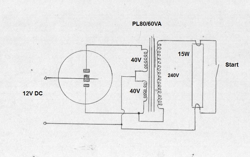
Out of my collection of transformers,
I found a Ferguson PL80/60VA to work rather well. Now, anyone familiar
with these Ferguson transformers will recognise the power rating in the
type number; 60VA.
That is way overpowered for driving a
15W tube of course, but the reason for trying this transformer was the
turns ratio. I had tried a few other types to start with, but the secondary
current (240V winding) was excessive. The 40-0-40V type was the highest
I had, so tried that. It looked promising, with a 100W bulb causing the
voltage to drop to a likely amount, so then substituted the fluorescent
tube.
Initially, the tube wouldn't ionise properly
- the turns ratio was too little. So, we needed a higher output voltage
off load. A 32-0-32V transformer might be suitable, but didn't have one
to hand. Instead, I took the simple way out and just added part of the
primary voltage to the secondary, auto-transformer style. The full 80V
primary in series was too much, but just using one 40V winding worked very
well.
The tube started easily, and primary current
was 1.2A at 12V DC input. That is an input power of 14.4W, and with inverter
losses, the tube is obviously receiving less than it's rated 15W. However,
it was not actually noticeably dimmer than a normal mains operated 15W
tube. At a guess, it was probably operating at about 12W. (I didn't actually
measure it).
Thus encouraged, I tried a 20W tube. This
wouldn't start unless both 40V windings were in series with the 240V winding,
and even then current draw at 12V was only 900mA (less than 10W into the
tube).
Obviously, a different transformer would
be required for 20W tubes. 40W tubes are pushing the ratings for ordinary
radio vibrators so did not consider them.
The concept of using a standard mains transformer, without any other current limiting device, seems to have been proven. However, it must be pointed out that I did not measure current over a variation of input voltage. Anyone thinking of duplicating the circuit would be wise to see the tube won't be overloaded with the input voltage rising to, say, 14V. Also, despite no sparking visible at the vibrator contacts in the test circuit, a primary buffer capacitor should be fitted. Just because the contacts on a vibrator aren't arcing, it is possible for material transfer to take place. Of course, the capacitor value depends on the transformer, and has to be found experimentally to get the correct waveform.
Given the experimental nature of this circuit,
it is impossible to specify other suitable transformers. The Ferguson used
in the test circuit is a now obsolete type anyway, and is much larger than
required.
Therefore, it's a circuit for someone
with a good collection of different transformers and who is prepared to
experiment. It does seem however, that the two primary windings need to
be somewhere in the region of 30 to 40V, with a 240V secondary. Obviously,
the input current and voltage must not exceed the tube rating. It's wise
to use an incandescent bulb to get an idea of the regulation characteristics
first.
I did not try a glow tube starter, but
it would appear that provided the unloaded secondary voltage is high enough,
one should work. An FS2 would be a good choice, as these are designed for
120V single tube, or twin series tube 240V fittings.
Given the high cost of postage, I'm not intending to acquire any more, except for a 6V model. That would be convenient for use in the Model T.