While the valve
pulse counting FM receivers presented elsewhere on this site work very
well, there was still a need for a solid state version. I envisaged such
a set might be used as a small portable battery powered receiver, allowing
good quality FM reception without the problems of special parts and the
multiple tuned circuits required for conventional superhets.
Most constructors these days just use
a TDA7000 IC for home made FM receivers. It works very well, but in a way
it is cheating as it's really a case of RF in, audio out, with a few minor
components. It also requires a carefully designed printed circuit board.
The challenge here was to make a proper
FM receiver with all discreet components, and like the valve sets, have
only one tuned circuit.
This has been a long term project which
I started back in the 1990's and revisited a few times over the years.
While there was no difficulty in getting the excellent sound quality, the
problems were caused by a very critical and insensitive frequency converter
stage. As always, the valve circuits just performed better.
In 2011, I made a considerable improvement
with the design and it was "almost good enough". Now, in 2016, that design
has been improved further and the receiver is quite practical for everyday
use with no critical controls.
Designs for solid state pulse counting
receivers have existed since the 1960's, but like their valve counterparts
have never been widely publicised. Again, the technique was mainly confined
to the UK and Europe for home constructed sets.
The solid state designs follow the same
basic design; a frequency converter producing a 200 kHz IF which is then
amplified using resistance coupled amplifiers. This is limited (clipped
into a square wave), and then differentiated before driving a pulse counting
or tachometer circuit, which then provides the demodulated audio.
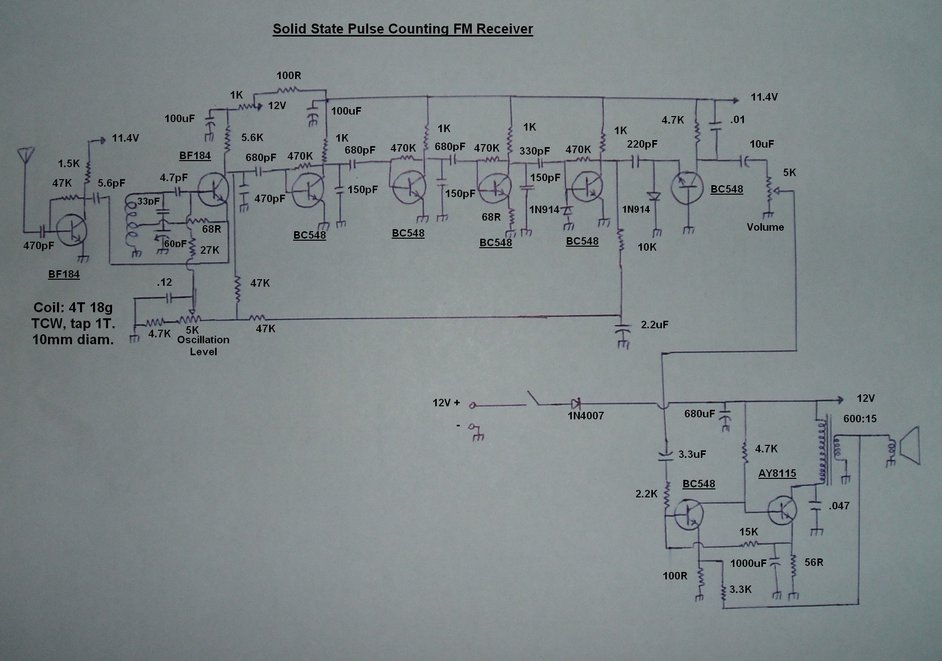
The Circuit.
RF Amplifier.
This is a very simple stage which is the
same as initially used with the 6
transistor super-regenerative receiver. As can be seen, it is untuned
for simplicity and has little gain. Its main purpose is to isolate the
aerial from the following converter stage. If not isolated, loading effects
will affect the operation of the converter and can stop it working altogether.
Here, a BF184 operates as a self biassed
resistance coupled amplifier. The low collector load ensures some gain
at VHF, although not as much as if the circuit was tuned. The input is
isolated by a 470pF capacitor which functions as a simple high pass filter.
It also prevents the bias being short circuited if the aerial has DC continuity,
such as with a folded dipole, or where a balun exists.
Frequency Converter.
This, more than anything else was the
real challenge. I tried several types of configuration here using both
silicon and germanium transistors, along the lines of the various magazine
projects shown further down.
While they all could be made to work,
the operating conditions seemed excessively critical, and sensitivity was
quite poor, with 100uV typically needed for quiet reception.
The idea of separate oscillator and mixer
stages was considered, but it would be getting away from the simple design
of an autodyne converter.
Then I looked at the 6 transistor super-regenerative
receiver circuit and its detector stage. This had particularly good stability
and non critical adjustment, so it would appear to hold promise as an autodyne
frequency converter.
With suitable modifications made; mainly
by substituting a fixed voltage for the original sawtooth quench voltage,
it did indeed work quite well.
Another BF184 is used as a Hartley oscillator.
If tuned so its oscillation frequency is 200 kHz away from the station
carrier, then present at the collector is a 200 kHz IF. The VHF signal
present is bypassed to earth by the 470pF, also connected to the collector.
Importantly, the 470pF is not enough to bypass the 200 kHz IF, so this
passes through to the first IF amplifier.
The incoming RF signal is fed into the
emitter, as tapped lower down the oscillator coil, the loading effects
of the RF amplifier are reduced. Base bias is via the 27K resistor, fed
from a 5K pot. Initially, the 5K pot was fed with a regulated 1.4V supply.
Because of the critical bias setting, two series connected diodes were
used in a shunt circuit to produce this 1.4V. Without this, any supply
voltage variation would have a serious effect. Because of changes in oscillator
performance from one end of the band to the other, it was necessary to
readjust the bias control as the receiver was tuned, if maximum sensitivity
was to be obtained.
A big improvement was had by rearranging
the bias supply in a DC feedback circuit. Now, the bias comes from the
collector voltage via the 47K resistor. If the transistor draws more current,
the collector voltage falls, and then so does the bias. This reduction
in bias then allows the collector voltage to rise again and offset this.
It is a standard bias stabilising configuration used in many transistor
circuits. Using a spectrum analyser, it could be seen that the amplitude
of the oscillation was much more constant across the band, and for all
practical purposes the oscillation level control only needed to be set
once at the low frequency end of the band. The final improvement was an
AFC circuit, which will be discussed later.
The tuning capacitor used is the 60pF
oscillator section of a modern plastic AM radio type. The 160pF aerial
section is not used, but could be if an AM tuner was also incorporated.
The series 33pF limits the tuning range. Ideally, a single 15pf tuning
capacitor would be used, but these are not as common. It should be pointed
out that using a series capacitor with a larger than desirable tuning capacitor
does cause the tuning adjustment to be non linear. The effect is that the
higher frequency stations are closer together than those at the low frequency
end of the band.
IF Amplifiers.
Here I experimented with several circuits
which were really all much the same except for component values. The one
I settled on was taken from a dual conversion circuit from the internet.
It actually appeared to be properly designed for the required frequency
response.
Each stage is the same, based on a BC548
transistor, and there are three such stages. High frequency roll off is
provided by the 150pF capacitors between collector and earth on each stage.
Low frequency roll off is conversely provided by the 680pF base coupling
capacitors. The third IF amplifier includes a 68R emitter resistor for
stability.
No doubt, one could use an op-amp if one
wanted to get away from the discreet component design.
Limiter.
The amplified 200 kHz FM signal needs
to be squared up prior to feeding the detector stage. This is done with
the fourth BC548 which operates with an inverse connected diode between
base and earth, clipping the negative peaks. Likewise, the positive peaks
are clipped by the base-emitter junction of the transistor. Provided the
signal strength is sufficient, the voltage here will be strong enough to
drive both diode junctions into conduction.
Detector.
The clipped 200 kHz FM signal is now differentiated
with a 220pF capacitor. This feeds another diode-transistor circuit which
is where the so called "pulse counting" takes place. Imagine the base-emitter
junction of the fifth BC548 is a diode. It can be seen that when a positive
pulse is received that the 1N914 conducts and charges the 220pF. The BC548
base-emitter junction is reverse biased and no collector current flows.
When the pulse goes negative, the 1N914 is reverse biassed, but the base-emitter
junction is now forward biassed by the discharging 220pF, and collector
current flows causing the collector voltage to fall.
Note the .01uF capacitor in parallel with
the 4.7K collector load. This averages out, or filters, the pulses present
at the collector. Now imagine what happens when this circuit is presented
with FM.
If the frequency is low, the pulses are
further apart. Therefore the average collector current is low. When the
frequency is high, the pulses are closer together, effectively present
for more time. So, average collector current is increased. In this way,
the voltage across the 4.7K//.01uF varies at the same rate as the pulse
repetition. The result is the original audio signal.
Audio Amplifier.
This is a circuit configuration I have
used for many years in many projects. Not being a fan of class B designs
with their distortion, I prefer class A. Simplicity is a further attribute
of the single ended class A design also. I also have a dislike of IC audio
amplifiers, especially the LM386 with its noisy output.
This circuit uses yet another BC548 as
the first amplifier and this is direct coupled to the AY8115 output transistor.
The AY8115 is incidentally a Fairchild type unique to Australia and was
made here.
A 600 ohm to 15 ohm transformer couples
the AY8115 to the speaker or headphones. The external speaker and headphone
sockets have not been shown on the circuit as their method of inclusion
is obvious.
The collector load of the BC548 is the
4.7K resistor, which also supplies bias to the AY8115. There is a 56R emitter
resistor for the AY8115 which operates in a bias stabilising circuit. The
voltage drop across this biasses the BC548 via the 15K. If the AY8115 current
increases, the voltage across the 56R increases and the BC548 conducts
more. This causes its collector voltage to fall which in turn reduces the
bias on the AY8115. Across the 56R is a 1000uF capacitor to prevent reduction
of gain. A sample of voice coil voltage is fed into the BC548 emitter
out of phase, by means of the 3.3K and 100R resistors, so as to introduce
negative feedback and a reduction in distortion. Output power is 77mW before
clipping. If a transformer with an 8 ohm secondary is used instead of the
15 ohms specified, the 3.3K feedback resistor should be reduced to 1.5K.
The speaker transformer I used is a 600
ohm to 15 ohm line transformer. With a rating of about 3W, it is overkill
for this circuit, but the large core gives a very nice bass response, especially
evident when listening through decent headphones.
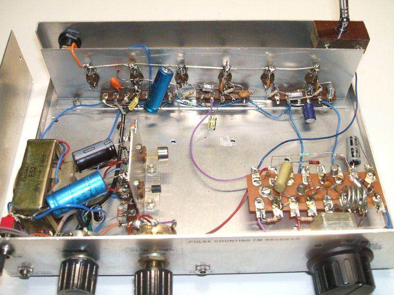
Inside view of receiver. The experimental origins are clear to see.
At the back is the IF strip and detector. Left front sub chassis is the
AF amplifier, and the tagboard at the right contains the VHF circuits.
Automatic Frequency Control.
Up to this point the circuit works fairly
well. However, tuning was still fairly critical because the how the tuning
capacitor had been earthed. Because it is a plastic type used in AM radios,
the shaft is not directly earthed to the chassis, but rather through about
20mm of lead inductance. Although a plastic knob had been used, the shaft
was still metal and some hand capacitance was evident. Ideally, the shaft
should be directly earthed by means of a sliding brass contact, or better
still with a panel mount variable capacitor where the moving plates are
earthed to the mounting. This is another example of short leads having
enough inductance to cause problems at VHF.
Despite the RF amplifier, there was still
a slight amount of detuning when the aerial was touched.
Obviously, an AFC circuit would be desirable.
Looking at the circuit, we need a point where the average voltage is proportional
to the signal strength. The detector is no good because the signal has
been clipped and will not vary in amplitude. The ideal point is the limiter
collector. Here the average voltage rises with an increasing signal strength.
A 10K resistor and 2.2uF capacitor filter out the pulse variation, providing
steady DC.
As to how the control the frequency converter,
it just so happens that the oscillation frequency does vary with the bias
setting, and so this can be used to inject the AFC voltage. The voltage
across the 2.2uF is introduced to the BF184 bias circuit via another 47K
resistor.
In effect, the BF184 is stabilised three
ways. Firstly by the collector feedback described previously. This sets
the initial DC conditions. Secondly, this initial bias condition is optimised
by the AFC voltage. The bias is automatically adjusted to the point where
strongest signal is obtained. Thirdly, because the bias also controls the
oscillation frequency, this too is optimised for maximum signal.
It is in fact quite practical to include
a tuning / signal strength meter by monitoring the voltage across the 2.2uF.
If a moving coil meter was to be used for this purpose, a suitable buffer
with DC offset would be required.
The result of the AFC circuit is such
that oscillation level control is no longer required on the front panel.
It can be replaced by a trimpot.
Power Supply.
This is 12V DC at about 50mA. In practice,
about 11 to 13V is suitable. A diode provides reverse polarity protection,
and there are the usual electrolytics and decoupling circuits.
Performance.
Like all other single conversion pulse
counting receivers, there are two tuning points; one each beside the carrier.
This can be useful if there is interference because often better reception
can be obtained by using the other tuning point. I strongly recommend a
vernier drive for the variable capacitor. Direct knob tuning works, but
with the low IF, tuning is very sharp.
Sensitivity is about 30uV for the noise
to start to drop off. In this regard, the circuit is comparable to the
Fremodyne. At my location with just the chassis mounted telescopic aerial,
all the main Sydney stations about 80km away can be received clearly. However,
it is not a DX set and the valve designs are still better for sensitivity.
The effects of having AFC is very noticeable
with a much less critical tuning control, and touching or moving the aerial
does not detune the receiver.
It was noticed that oscillator pulling
was sometimes evident, before the AFC was added; this being because of
the low IF. This does not seem to happen with the valve designs, possibly
because the carrier voltage is considerably less than the voltage at which
their frequency converters operate with.
The small 75mm speaker mounted in the
cabinet lid does not do justice to the sound quality, and is provided merely
for convenience. Much better results are obtained with a larger speaker.
Constructional Notes.
As with any other VHF circuit, layout
and good earthing are important. It is amazing the amount of constructors
who attempt to build VHF receivers on a solderless breadboard! These are
the people that complain of unstable designs. Ideally, a metal chassis
or box is the best kind of construction.
The oscillator coil is four turns of 18
gauge (or similar) tinned copper wire, self supporting air cored with a
diameter of 10mm. The tap is at one turn. The particular tuning capacitor
will determine the exact tuning range, but with the 60pF oscillator section
of a plastic AM tuning gang, and the 33pF series capacitor shown, the range
is 85 to 125MHz. There is of course further adjustment by means of the
trimmer capacitor and by spreading or contracting the spacing of the coil
turns.
A vernier dial will go a long way to make
tuning easier.
The front panel oscillation control shown
on the prototype is a legacy of previous experiments and is no longer needed.
A trimpot will suffice, and if results of the prototype are anything to
go by, even that could possibly be dispensed with. However, the transistors
another constructor uses might operate better under different conditions,
so do not be too hasty in omitting this control. In the prototype, mid
setting of the control is satisfactory.
If for some reason, the AFC circuit is
not required, omit the 10K, 2.2uF and 47K in that part of the circuit.
The oscillation level control should be made available as a front panel
control in this case.
The 680uF is an obscure value of capacitor,
so use 470uF or 1000uF. Likewise, the .12uF associated with the oscillation
level control can be replaced by .1uF.
For the AY8115 audio output transistor,
any similar modern type can be substituted such as BD139.
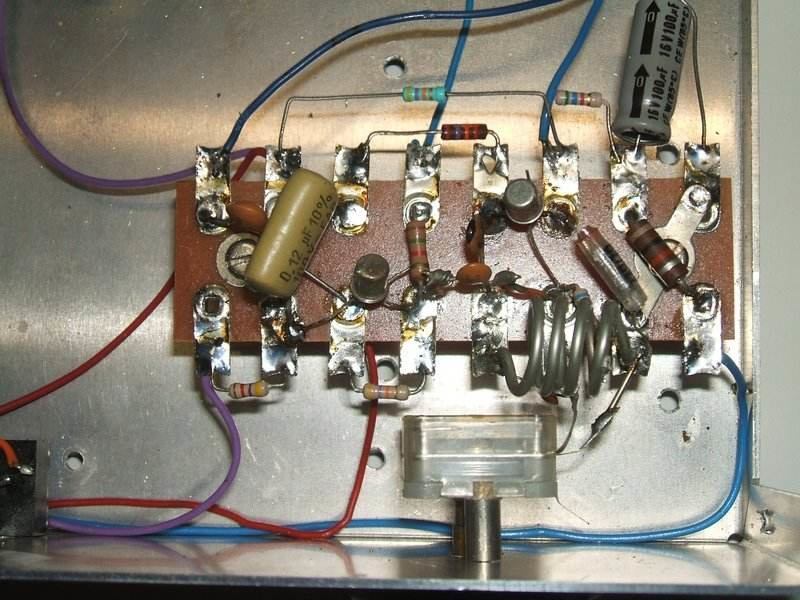
Close up of the RF amplifier and frequency converter.
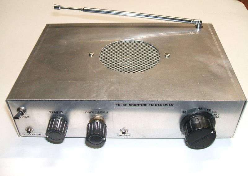
As can be seen, I made up an aluminium
box for the receiver, with a sub chassis for the audio amplifier and another
for the IF amplifiers, limiter and detector. The RF amplifier and frequency
converter are mounted on a tagboard right next to the tuning capacitor.
The box is larger than required, but as this started out as an experimental
receiver, I preferred a spread out layout so as to make any changes easy.
Apart from the tagboard, all the transistors are mounted in sockets, and
the construction resembles that used with valves. The receiver could be
made much more compact using a PCB; something which is practical now that
the design is finalised.
A 75cm telescopic aerial is mounted at
the back corner of the chassis in an insulating block. This is more convenient
for portable use than having to use an external aerial, and gives more
predictable results than a piece of wire. Note that 75cm is a quarter wavelength
of the FM band.
Other Circuits.
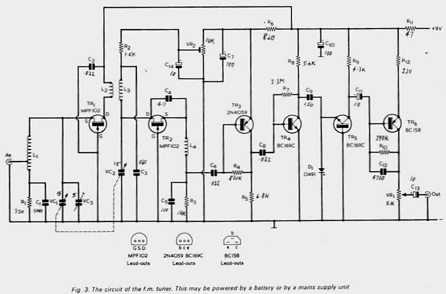
From UK magazine "Radio & Electronics Constructor", December
1974 & January 1975. I found this to have the worst frequency conversion
circuits of all I tried.
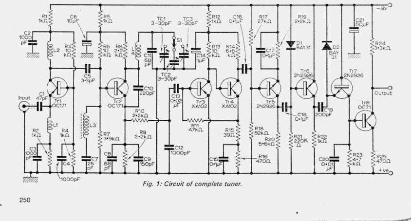
From "Practical Wireless" August 1967. The biassing of the IF transistors
was unnecessarily complicated, and the operating conditions of the frequency
converter critical. I was not impressed by the sensitivity either.
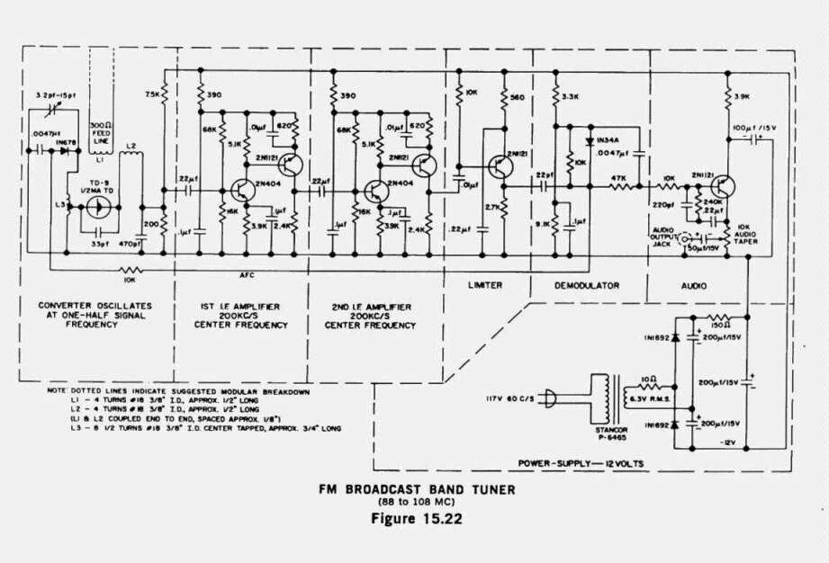
From the "General Electric Transistor Manual" 1964. It uses a tunnel
diode for the converter. Again, the IF amplifiers seem unnecessarily complicated.
I have not tried the circuit, although my previous experiments with tunnel
diodes make me sceptical.
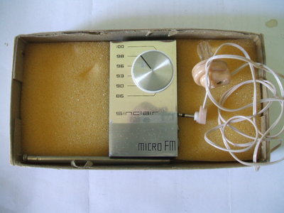
Sinclair Micro FM.
There was a commercially made kit, the
Sinclair Micro FM, for sale in the UK during the late 1960's. It would
be familiar to anyone reading 1960's English electronics magazines. It
was a pulse counting circuit with untuned RF amp, autodyne converter, and
used Micro Alloy Transistors. Claimed sensitivity was 3uV and the receiver
could drive an earphone and had a line out socket for an external amplifier.
The few reports I've found on the internet
suggest sensitivity was less than this. The PP5 battery required is obsolete,
and was apparently already difficult to obtain at the time the Micro FM
was being sold.
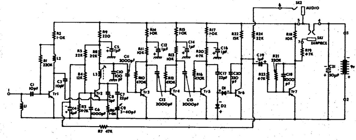
Circuit of the Sinclair Micro FM.
For those wishing to try building it, L1
and L2 are 14 turns around a 470K resistor. Wire gauge is not specified,
but I'd guess about 25B&S. L3 is six turns around a plastic former
with adjustable ferrite slug.
The former and slug would appear to be
similar to the modern Neosid type of thing. Brief operation is as follows;
Tr1 is an untuned RF amplifier to prevent aerial loading, and to provide
some gain (I'd guess about 10dB max). Tr2 is a self oscillating converter
(i.e. autodyne). RF is filtered off by C10, leaving a 120 kHz IF. This
is amplified by Tr3 and Tr4. Tr5 also provides amplification but is the
limiting stage to provide a clipped waveform to the pulse counting detector.
This consists of C17 as the differentiator, and D1 and D2 which are the
diode pump. Tr6 provides audio amplification, with C20 integrating the
detected pulses into a smooth audio waveform. Line level audio is available
from this stage. Tr7 is merely an earphone driving stage. AFC is provided
by using the DC at Tr6's collector to control Tr2's oscillation frequency.
R7 and C4 are low pass filter to remove the audio component from the control
voltage.
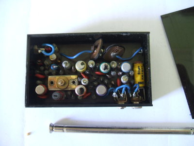
My Sinclair Micro FM receiver. This has yet to be restored.
Introduction
Hello all. My name is David Smith. I live
in the UK near Manchester. I have written this because I have constructed
Johns transistor pulse counting FM receiver and been very pleased with
the result. I have tried to set out the way I went about it and I hope
that will encourage you to build it too.
I have had an interest in radio and electronics
as a hobby since I was a boy. As a teenager I made a superhet FM tuner
from a construction article in Practical Wireless (February and March 1969).
That was a long time ago. I am retired now and am able to spend more time
on my hobby. Since I retired, I have joined the British Vintage Wireless
Society, restored several vintage valve radios, constructed a valve amplifier
and made a number of other wireless related projects.
I was looking for something new to make
when I came across Johns website and read his articles on pulse counting
receivers. These were not something I had heard of up until then. They
seemed to have a lot of advantages and most importantly did not require
complex equipment to accurately align tuned circuits. I thought the transistor
pulse counting receiver was something I could tackle, particularly with
the detailed article John had written about it.
Initial Assessment
Before starting any construction, I read
and re-read Johns article on the receiver until I was sure that I understood
it.
The design consists of three separate
sections. First an RF section, then the IF section and last an AF amplifier
that drives a small internal loudspeaker. I decided that I would omit the
AF amplifier because I already had a suitable transistor amplifier with
its own loudspeaker.
I wanted to understand in more detail
how the limiter and discriminator sections worked and traced their origins
back to an article in Wireless World magazine entitled The Diode Transistor
Pump by D. E. ON. Waddington, "Wireless World", July 1966. This
and all the other magazines I refer to, can be found on the American Radio
History website (www.americanradiohistory.com
) which is well worth investigating.
What I already knew about construction
at VHF frequencies can be easily summarised; layout is critical, connections
need to be short and a rigid metal chassis is necessary.
I knew this meant that construction of
the RF circuit board and associated components would be the critical items.
The IF stage operates at around 150 200 kHz and, as a result, construction
would be much less critical.
RF Circuit Board
In order to stand the best chance of success
I aimed to copy precisely the layout of the RF tag board that John built.
I studied the circuit diagram and the photograph John had put in his article
and very carefully sketched out the connections until I was sure I had
them right. I did not find this easy and it took me quite a while to do.
I persevered with this because I thought it was the key to success and
I still do. I have redrawn this using a CAD program:
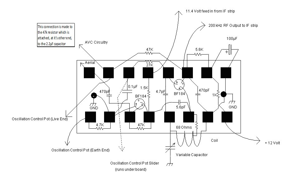
The drawing is actually full size and can
be copied into a word processor and stretched out to fill a sheet of A4.
If you decide to use this layout it is worth being sure you can tie up
all the external connections with Johns circuit diagram before starting
construction.
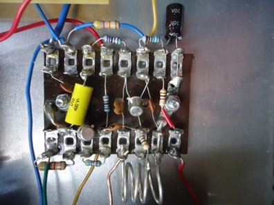
I wanted to maximise my chance of success
and so I used only the components specified by John. The coil is also exactly
as specified by John: it is air cored and is four turns of 18 SWG tinned
copper wire wound on a 10mm diameter former. It is clearly visible in the
photograph below. The tuning capacitor is a 15pF air spaced variable fitted
with a slow motion drive; I got this from a scrap VHF valve radio given
to me by my brother.
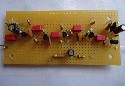
This is my completed circuit board I
have orientated it to match the drawing above.
IF, Limiter and Discriminator Circuit
Board
In comparison to building the RF section,
construction of the IF amplifier and discriminator was straightforward.
I simply followed the circuit diagram when building the board. I wanted
to make the board reasonably small without trying to overcrowd it and,
having assessed the physical size of the components, I concluded that a
piece of plain 0.1 inch strip board of about 4 inches by 2 inches would
be satisfactory. I used the components specified by John and hard wired
them together.
This is my completed circuit board:
Assembly of the Receiver
For a chassis, I used a two part aluminium
box of 8 x 6 x 3 (WxDxH) that would provide a rigid mounting and a good
earth plane. A die-cast box would also be suitable and easier to find too.
I prepared a layout diagram for the chassis
and ensured it matched the arrangement shown in Johns photographs as closely
as possible. I drilled the chassis to accommodate the various controls,
circuit boards and sockets in accordance with the layout drawing. I loosely
fitted the various controls, circuit boards and sockets on to the chassis
to ensure there would be no nasty surprises later on. After that, I wired
up the tuner. I added an LED On/Off indicator which was my only deviation
from Johns design.
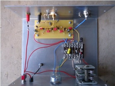
My completed tuner is shown below:
Testing the Pulse Counting Receiver
I connected an indoor dipole aerial to
the receiver and an external audio amplifier. The radio immediately worked
properly with all the local FM stations coming in clearly. I did not need
to make any alterations to the tuning coil or anything else for that matter.
The slow motion drive made tuning easy and I quickly found that the set
was very stable, quiet in operation and provided excellent sound quality
with no noticeable sibilance. There were no hand capacitance effects and
no hiss when tuned in. The oscillation level control needs little adjustment
in use and is not particularly sensitive; the mid-point of its travel is
about the right setting. Only about a quarter of the FM tuning capacitors
range is used in covering 88 108 MHz but with the slow motion drive it
isnt really a problem and I did not attempt to alter it.
With a 12 volt supply the current drawn
is 24mA. I did try running the receiver from a 12 volt switched mode power
supply; this was a bad idea the noise introduced was intolerable. I eventually
bought a 12 volt DC supply using a traditional mains transformer and this
was entirely satisfactory with no additional hum or noise whatsoever.
Conclusion
I am very pleased indeed with this receiver.
I planned the construction carefully, used exactly the components specified
by John, and tried to follow all his advice on construction. I now have
an FM tuner that receives all the stations I am likely to want to listen
to, sounds excellent, does not drift in frequency, needed no alignment
and has nothing to go out of adjustment. Like all simple pulse counting
receiver designs there are twin peaks for tuning each station but you soon
get used to that.
With the exception of the tuning capacitor
all of the components are readily available. Suitable air spaced tuning
capacitors do come up on eBay, and elsewhere, from time to time and are
worth keeping a lookout for; otherwise you could use a polyvaricon as John
did.
Addition of a Tuning Indicator
After building this receiver I could not
resist trying Johns valve
based pulse counting receiver designs. These too were excellent. I
built design No.5 which has the magic eye tuning indicator. This showed
me the value of such a device for accurate tuning. I kept thinking about
the comment John had made in his article that a tuning indicator could
be added to the transistor version by measuring the voltage across the
2.2µF capacitor in the AFC line.
The first thing was to get some idea of
the AFC voltage. I have a digital voltmeter and trying to get an accurate
measurement with this was difficult; eventually I found that 4.6 volts
was the maximum I measured with the receiver tuned in to a strong local
station. At least this gave me something to start with.
I looked for a suitable analogue voltmeter
circuit and after some time I came across the circuit below. It looked
ideal. It is reasonably simple, has a high input impedance, runs from a
single positive rail supply and, with suitable voltage dropper arrangements,
I saw no reason why it should not be powered from the tuners 12 volt supply.
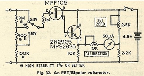
This circuit is from a design first published in Electronics World in February 1967, but with some modifications suggested by another correspondent to that journal in the November 1967 issue. Initial reports on the circuit as a voltmeter were enthusiastic. These two articles are worth reading if you are interested in adding the tuning indicator to the receiver.
Preliminary Tests
I built a test circuit using a 2N3819
(Fairchild) FET and a BC549C NPN transistor. I used these transistors because
I had them to hand; I dont think they are at all critical and anything
roughly equivalent is worth trying. I used 10k linear potentiometers for
both the set zero and calibration controls. I used a 100µA meter
and built the voltage divider exactly as shown above. I powered it from
a 4.5 volt battery. The set zero control was adjusted so that the meter
read zero when there was no input voltage applied and the calibration control
was adjusted so that a 3 volt test voltage read correctly.
I was impressed with the circuit. It worked
well and made a good analogue voltmeter. There were no problems with it
and I found that it could quite happily measure its own supply voltage,
meaning that with suitable switching you could perhaps use it as a battery
condition indicator as well as a tuning indicator
I used this test circuit to measure the
receivers maximum AFC voltage, which was easy to do as the analogue meter
clearly showed the peak. I was pleased to find that 4.8 volts was the maximum
I measured; not so very different from that which I had measured with such
difficulty using a digital meter.
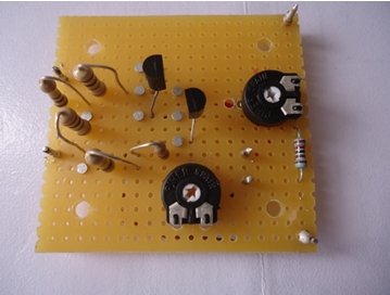
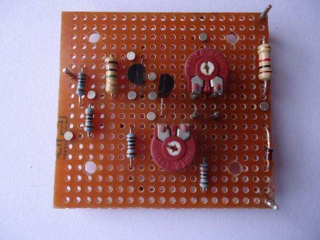
Building the Circuit
Satisfied that the design would be suitable
I now made up the circuit on a small piece of plain strip board using two
5k trimmer potentiometers for the set zero and calibration controls. I
used the same two transistors that I had used in my trial construction.
I devised a simple voltage divider for the input and switched on. When
I tested it, I found to my annoyance that the two 5k trimmer potentiometers
did not give enough range to adjust the set zero and calibration controls
properly. I should have used 4.7k potentiometers in my test circuit instead
of 10k ones it would have saved me quite a lot of trouble.
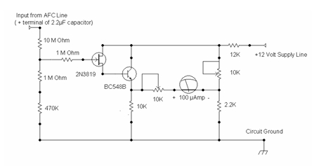
There followed a degree of experimentation.
The underlying cause quickly became plain. The variation in FET parameters
is so great that a circuit must have sufficiently wide-ranging adjustment
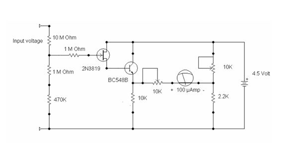
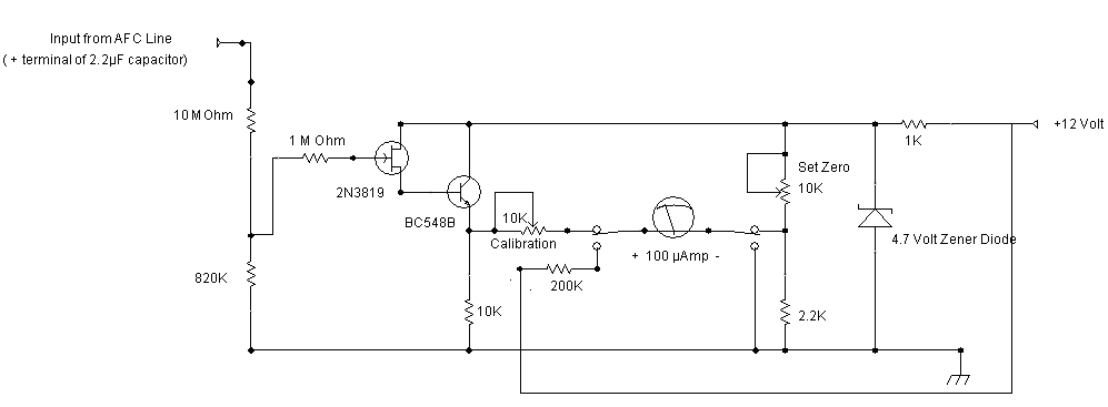
to deal with this. This is hardly a new observation. I made a new version
of my test circuit. This time I used a new 2N3819 FET (Motorola) and a
new BC548B silicon transistor. The voltage divider I used at the circuit
input had a 10M resistor in series with a 1M and 470k resistor. As before,
I used 10k linear potentiometers for the set zero and calibration controls.
This is the circuit diagram:
Only when I was satisfied that this version worked perfectly did I re-build the circuit on a small piece of strip board for inclusion in the receiver. This time I used two new 10k trimmers for the set zero and calibration controls. The circuit was powered from a 4.5 volt battery. The set zero control was adjusted so that the meter read zero when there was no test voltage applied and the calibration control was used to give Full Scale Deflection with a 6 volt input voltage. This time everything worked perfectly.
My final version:
I measured some voltages and currents;
the emitter voltage of the BC548B with the 100µA meter disconnected
was 1.08 volts (for comparison the earlier version with the Fairchild FET
had been 1.8 volts). The total current drawn was 0.6mA with no input voltage
rising to 0.7mA when measuring 4.5 volts; the earlier version had drawn
1.1mA. These variations in voltages and currents reflect the variability
of FETs.
Installation of the Tuning Indicator
First, I needed to ensure the tuning indicator
would operate through a suitable voltage dropper from the tuners 12 volt
supply. The simplest way of doing this was to use a voltage dropper resistor
in series with the positive supply lead. I was aware there might be problems
with doing this but a 12k resistor in series with the positive supply line
turned out to be entirely satisfactory giving me 4.6 volts as the tuning
indicator supply voltage. Some minor adjustment of the set zero and calibration
trim pots was needed but that was all. Other FETs might require a different
voltage dropper from the 12k I used. The easiest thing to do is to measure
the current drawn using a 4.5 volt supply and calculate the dropper resistor
you will need to bring your supply line voltage down to 4.5 volts; something
in the range 10k to 12k should do it.
In order to make room for the panel meter
the oscillation control potentiometer needed to be moved closer to the
tuning capacitor. I used a new miniature 4.7k linear pot to replace the
original standard size item.
A 50mm hole was now required for the meter;
a tedious job with much drilling and filing of metal required. The final
stage was to mount the tuning indicator circuit board. I took the input
to the tuning indicator from the positive terminal of the 2.2µF electrolytic
capacitor in the AFC line. This is the point recommended by John and it
is from the final IF amplifier transistor before the limiting stage.
For clarity I have included the final
circuit diagram of the tuning meter:
All the components were connected up; and
the tuner tested. All was well. The tuner worked just as before and the
tuning indicator gave a very clear indication of when a station was correctly
tuned. It does also give some idea of relative signal strength.
I re-adjusted the set zero trimmer so
that there was only minimal meter reading when tuning between the main
BBC stations around 91 MHz and then re-adjusted the calibration trimmer
so that my strongest station (BBC Radio 4 on 93.7MHz) gave me a reading
of 80% FSD. Because there is no inter-station muting the meter does respond
to the background noise between stations but tuning stations in correctly
is very easy to do.
This is the final version with the meter
and circuit board installed:
Conclusion
The tuning indicator is a nice addition
to the tuner. The circuit is entirely suitable for the task. It gives a
clear indication of when stations are correctly tuned. The tuning indicator
confirms that the receiver is very stable in use. I have left it switched
on for hours with no discernible drift a testament to the very effective
AFC circuitry John has designed for this receiver.
Because some minor adjustment of the set
zero and calibration trim pots was needed after installation I no longer
think the circuit can easily be used to check the tuners supply voltage.
Other than the problem with the FET variability
there were no other complications and I am pleased that I made the effort
to add the tuning indicator to this excellent receiver design.
I let John know by email what I was doing
and he has given me every encouragement throughout for which I am very
grateful.
D J Smith
14 July 2017
Transistor Pulse Counting FM Tuner
August 2017 Update
After I had completed the work on the
tuning indicator, I discussed the matter by email with John. He suggested
that a couple of alterations to the design might be worth considering.
First, that it might be better to use
a Zener diode to generate the 4.5 volt supply the tuning unit requires
rather than just use a simple dropper resistor in the 12 volt supply line.
Second, that it would be nice if the unit could also be used as a battery
condition indicator so that a user could easily check the battery voltage.
I said I would investigate these two suggestions and let John know what
I found.
First, I investigated Johns suggestion
about the Zener diode. I compared my simple dropper resistor arrangement
with a 4.7 volt Zener diode fed by a 1k? resistor.
Of course, I found that the Zener diode
arrangement maintained the 4.5 volts required by the tuning unit far better
than the dropper resistor alone. The receiver requires 11 to 13 volts for
normal operation and the Zener diode regulation over this input voltage
range is quite adequate. With the Zener diode in place, the tuning unit
draws 7ma compared with 1mA with a voltage dropper resistor. However, I
think the improved voltage stability is well worth the small extra current
drawn and I have added this to my receiver.
Next, I investigated Johns second suggestion
that the tuning unit could, by means of a voltage divider and a suitable
switching arrangement, be used to monitor the battery supply voltage. However,
I found that when the supply voltage dropped below eleven volts the set
zero function of the tuning unit went out of adjustment; the 100µA
meter showed an increase in current flowing through it and thus an incorrectly
high battery voltage reading. The Zener diode regulation was not good enough
for this purpose and I did not want to increase the Zener diode current
because of the adverse effects on battery life. This was not the right
solution and I considered how else I might approach it.
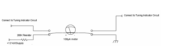
I thought it might be worth considering
an arrangement using just the 100µA meter movement with a 200k? series
resistor. This would give a voltmeter scale reading 0 20 volts; it would
not have a very high input impedance but this would not matter when reading
the supply voltage. A two-pole change over switch and a single resistor
would be all that was required as shown here:
This arrangement is not dependant on the
functioning of the tuning unit electronic voltmeter and always gives a
correct indication of the battery voltage. A test showed the meter and
a 200k? resistor worked well as a voltmeter. With 12 volts applied the
meter read 60µA; the user simply doubles the meter reading (or divides
by five) and interprets the result to get 12 volts. With a 0 100 meter
scale some sort of mental arithmetic is going to be necessary whatever
arrangement is adopted.
This arrangement was so simple and so
satisfactory that I incorporated it into my revised design. The final design
is shown here:
This is the circuit board I built:
To setup the unit connect a 12 volt power
supply to the circuit and adjust the set zero trimmer so that the 100µA
meter reads zero. With the input voltage divider values shown in the circuit
diagram above (10M? + 820k?) the meter has a Full Scale Deflection of 6.6
volts. Knowing that, you can then apply any convenient known input voltage
(say 4.5 volts or 6 volts) to adjust the calibration trimmer so that
the meter reads correctly.
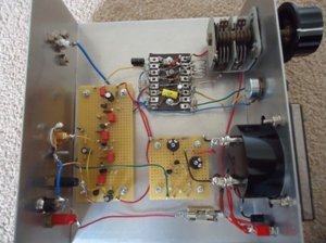
This is the receiver with the board installed:
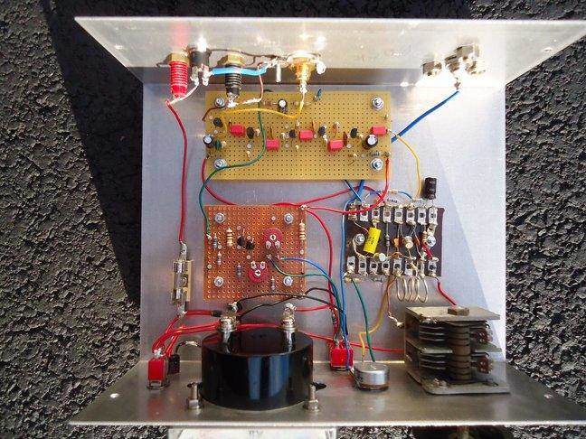
The small red toggle switch to change between
the battery condition indicator and tuning indicator is visible between
the meter and the tuning capacitor.
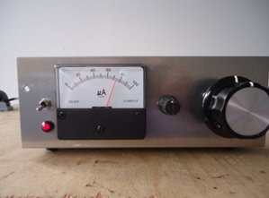
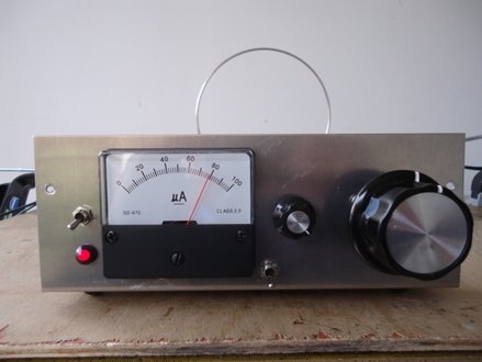
A front view of the revised receiver,
tuned to a strong local station:
Conclusion
The suggestion that John made about using
a Zener diode for regulating the supply voltage to the tuning indicator
was very worthwhile and I adopted it. The only drawback is the small additional
current drawn due to the action of the Zener diode. I have also been able
to add the battery condition function although not in quite the way we
originally discussed. The simple arrangement I have installed in my version
of this receiver works whatever the state of the battery.
If you decide to construct the tuning
unit you will find the circuit is trouble free. The only recommendation
I would make is to ensure that you do use 10k? trimmer potentiometers for
the set zero and calibration controls. If you use lower values you
may be lucky and find they work satisfactorily but it depends on the characteristics
of the FET you are using. I have not found any FETs where even 10k? trimmers
have not given enough adjustment range. If you happen to have just one
10k? trimmer, and are tempted to try your luck, then use it for the set
zero function.
Finally, I am grateful to John for his
helpful suggestions that have resulted in alterations to the tuning unit
which costs little to implement and add worthwhile improvements to the
design.
David Smith
03 August 2017