The first television sets released in Australia, during 1956, were based on U.S. and European designs, but it didn't take long for local input to evolve set design into something uniquely Australian. The 1960's was a time when the Australian electronics industry was booming. Every part of a television set could be, and was being made in Australia; from resistors to valves and semiconductors. From picture tubes to deflection components; it was all made here.
By 1970, transistor and hybrid sets were now becoming firmly established, particularly for portables, where the low power deflection requirements allowed a fully solid state design. Larger screen sets still used valves for the deflection stages, since high voltage high current transistors were still more expensive than valves. Typical of large screen hybrid designs at this time was the Thorn R2M, of British origin. Australian manufacturers were also gearing up for colour (to be officially introduced in 1975), so the era of solid state monochrome set design was a useful background in preparation for this. Sadly, it all came to an abrupt end after import tariffs were lifted in 1973.
There had been some transistor sets available in Australia since the early 1960's. These were invariably Japanese imports from the likes of Sharp and Sony, and were small screen portables. One Sharp model has been described here. By 1965, Pye had produced the first Australian set with transistors, which was the hybrid T23 chassis. It is interesting to note that it was the brands with European connections that really pushed the hybrid and solid state designs, such as Thorn, Pye, Philips, Astor, and Kriesler. Conversely, U.S. influenced designs such as those from AWA, National, and G.E., were still producing all valve portables in the early 1970's.
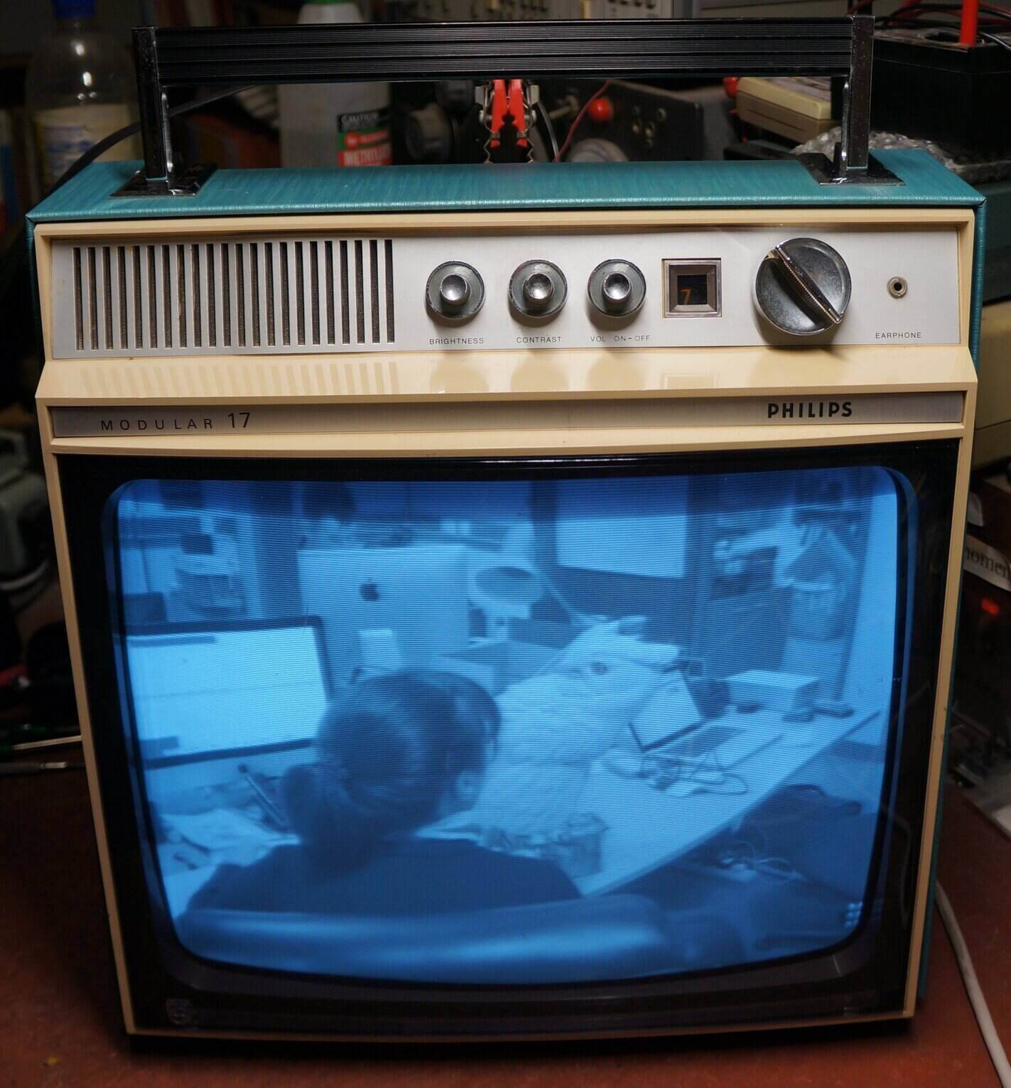
The Philips "Modular 17" described here is an example of what Australian design and manufacturing had achieved by 1968. Its claim to fame was the new "modular" design. This was supposed to make servicing quicker and easier, by simply replacing a whole sub assembly, rather than tracking down an individual faulty component. In practice however, it does seem that most technicians did just repair the sets in the normal way, since the time taken to get a new module would take longer than tracking down the fault. The modular design was used in 12", 17", and 23" sets; the 12" being fully solid state, and the others hybrid. Modular design was popular in Europe, particularly with Philips, and it continued well into colour production, and even with their N1500 and N1700 VCR's.
I already had two of the 12" versions and a 23" lowboy, so was familiar with the design, but this was the first 17" set I had seen. It has identical styling to the 12" models, but is just larger.
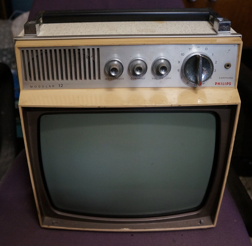
12" fully solid state. This set can also work on 12V DC.
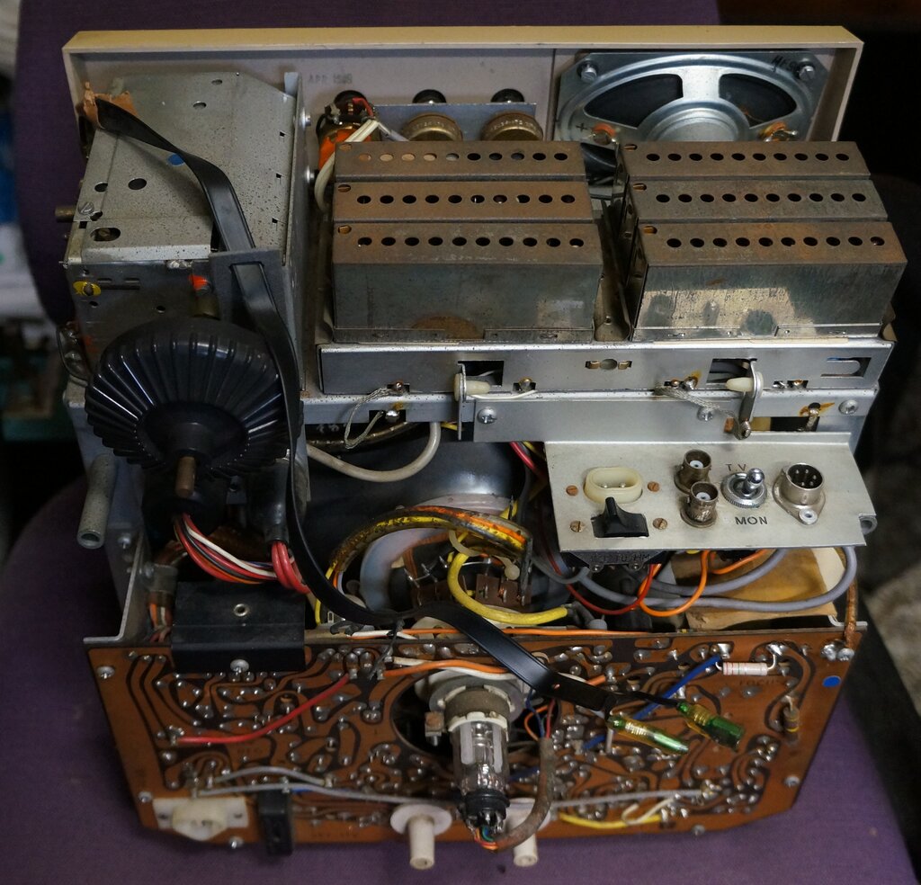
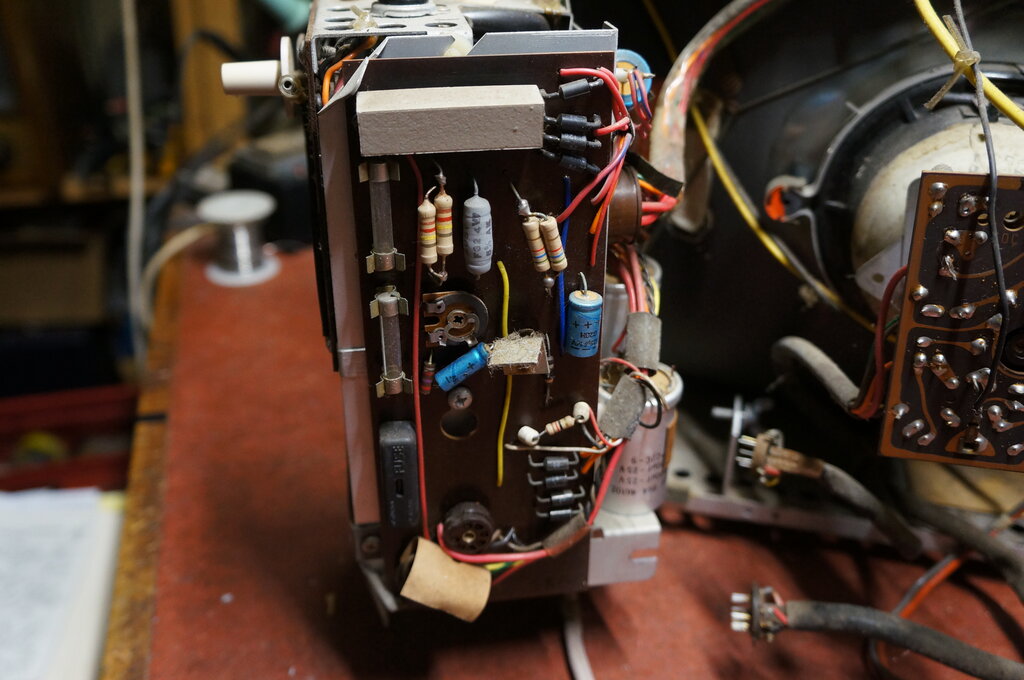
Inside the 12" set. This particular set had been modified to allow
use with a VTR, providing audio and video inputs and outputs. 12V input
and changeover switch to the left of the video connections.
This particular 17" set came to me from
a kind member of the HRSA, who had noted its excellent cosmetic condition,
and thought I might be interested. In its favour of course, was that it
was a portable, and a bit easier for me to find room for! In due course,
the set turned up and my initial reaction was of surprise at just how good
the set looked. Almost unused. And yet, it was 52 years old. No tarnishing
or pitting on the chrome plated surfaces, and no fading of the plastic.
From the capacitor date codes, I could see that it was made in 1970.
The set was manufactured at the Philips
factory, which had been established in the Adelaide suburb of Hendon in
1947. In the early 1970's television manufacture moved to the Melbourne
suburb of Clayton, but Hendon continued producing components.
Power Up.
Being as "modern" as it was and largely
solid state, I didn't feel any risk in simply powering it up straight away.
Also, not being full of paper capacitors means there's a good chance it
will work to some extent. It's 2022 now, and I feel it's safe to say that
electrolytics made after the mid 1960's don't yet need reforming before
the initial power up.
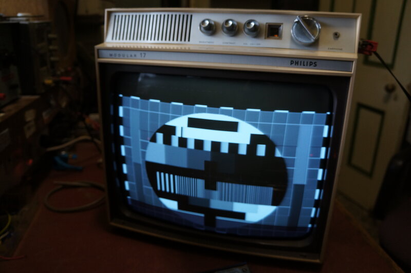
Sync pulses contain video, causing the frame oscillator to trigger
on black level instead of the proper pulse. Note the downward displacement
of the picture.
I wasn't at all surprised to see the set work straight away, and with an excellent CRT. Alas, it soon became apparent that the sync was being affected by picture content on certain scenes. Also, I noted the frame hold control was almost right at the end of adjustment - no doubt due to a high resistor. Otherwise, everything seemed good regarding contrast, brightness, sound, and picture geometry and definition.
Sync Separator.
I'd had this sync problem with the 12"
set shown above, and it was unsurprisingly caused by one of the low value
blue Philips electrolytics in the sync circuit. So, again, I reached for
the sync separator module expecting the same.
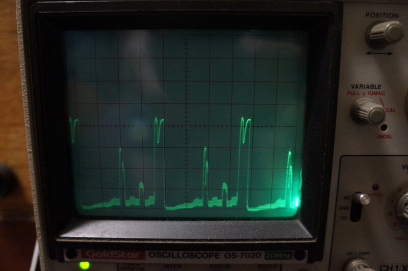
Frame sync pulses are distorted and video information is present
between them.
First thing that struck me was all the
IRC resistors. Even though Philips made their own resistors, a closer look
revealed that most in this set were the dreaded IRC type. These are now
are problem, since most have drifted high. It used to be just the higher
values, and in sets from the 1950's, but time has marched on, and these
days even the last of these resistors produced ca. 1970 are now suspect.
Nor are just the high values. In recent times I have encountered resistors
in the hundreds of ohms, and low kilohm ranges which have gone high. Vintage
radio and TV restoration is no longer just a matter of replacing paper
capacitors. If it has IRC carbon resistors, these all have to be replaced
too.
Anyway, checking the electrolytics did
not reveal any faulty ones, so next tried the resistors. All of the IRC
ones were at their upper limit of tolerance, or just over. Then I found
the 4.7k collector load for the sync separator transistor had doubled in
value. Unfortunately, replacing it didn't really solve the problem.
Altering the bias of the sync separator
transistor did cure the fault, but this should be unnecessary, since I
know from the 12" set it should work perfectly as designed. So, I decided
to simply try the sync module from the 12". This didn't fix it at all.
Then I tried the video detector and AGC module, in case that was distorting
the video going into the sync separator. It wasn't that either. At least
I didn't need to spend more time chasing a non existent fault in the modules.
Too Much Signal.
It actually turned out to be a simple
fix. The modulator I use to provide my TV signals is of high power; strong
enough to transmit across the house. I'd fed its direct output into the
Philips, which was evidently too much. It is a known characteristic that
solid state front ends cannot deal with very strong signals, in the way
valve circuitry can. And this was a perfect example. Connecting the modulator
through an attenuator fixed the problem.
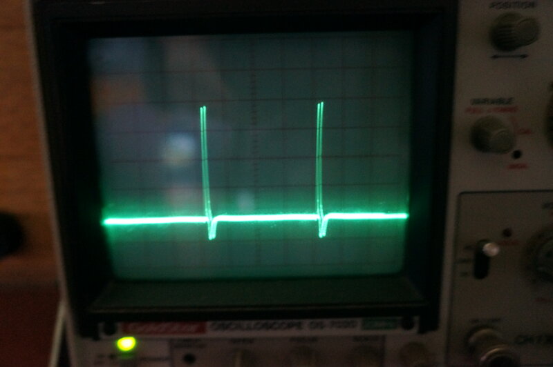
No video in the sync once the input signal was reduced.
This is not to imply the design is defective.
For normal off air reception, the AGC and control range is adequate. It
was just never designed for such a strong signal, and nor did it need to
be.
With that out of the way, the question
was where to go to now? To do a full and proper restoration would involve
replacing lots of IRC resistors. Interestingly, despite the 1970 manufacture,
there are still two paper condensers in the set. One is the usual boost
capacitor - which I had noted before I switched the set on, but felt it
was 'young enough' not to be a problem - yet. The other was in the frame
circuit. Why wax dipped paper capacitors were used this late has me curious,
since Philips were making their own 630V plastic types well before this
set existed. It is true though, that at the time paper capacitors were
not as unreliable as they are now. They hadn't yet clocked up years of
moisture absorption!
For now, I decided to simply leave everything
as is. The set works very well, and it is nice to have it all original
(except for the 4.7k resistor).
One weakness is the lugs securing the
plastic front panel to the chassis. The plastic has become brittle, and
all of them were cracked/broken. Also, unless the front panel is aligned
perfectly with the chassis, the lugs will be under pressure as the screws
are tightened.
I epoxied the lugs back together, but
if it's a recurring problem, I'll make up stronger aluminium brackets to
reinforce them.
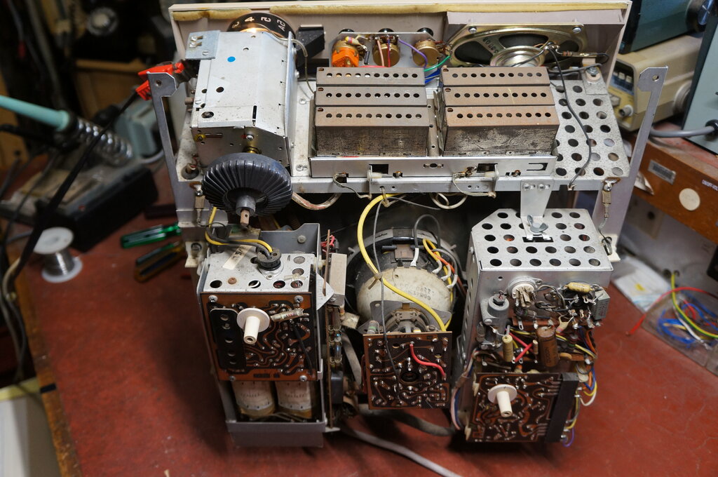
Rear view inside. Compact and built for service.
The chassis of the T284 is built around the CRT, with the front end circuit all on the top shelf above. The power supply and deflection circuits are assembled on two swing out chassis at the rear. With so much metal, and a Marviplate cabinet, the set is heavy, and I imagine some people would have difficulty carrying it. "Transportable" might be a more appropriate description.
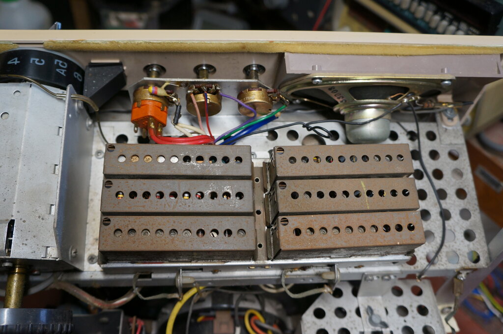
Set of modules contain the entire front end and audio circuitry.
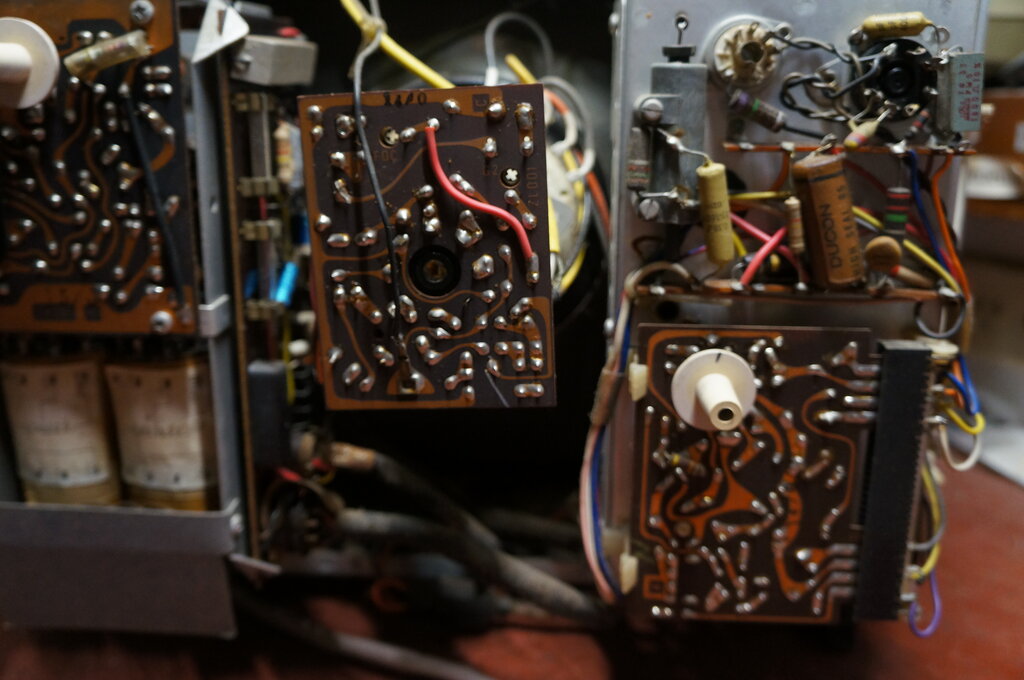
The Ducon paper boost condenser (C553) is visible here.
What is particularly convenient is that all the modules, including the power supply and deflection, can be simply unplugged and removed without having to desolder anything. It's clear that a lot of thought has gone into the serviceability of the design; more so than any other set that comes to mind at present.
The Circuit.
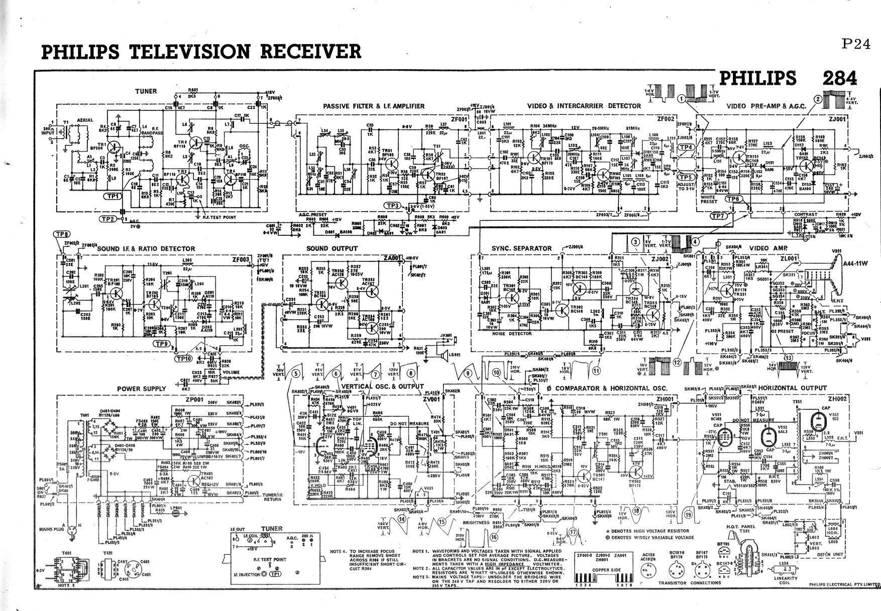
Original circuit for the 284. A few minor component changes and
a change to the AGC circuit had been implemented by the time my set was
built.
Apart from the two deflection stages, the circuit is entirely solid state. There are only four valves. Aside from the 12V regulator and audio output, all the transistors are silicon, being the well known BC and BF series. The service manual goes into quite some detail about circuit operation, which at the time would have been very important. While we take solid state electronics for granted now, remember that at the time it was all new, and those brought up with valves often had a hard time understanding it. A brief summary of circuit operation follows:
Tuner.
This is a type NT3017 turret tuner. Instead
of cylindrical coils, it uses printed circuit biscuits; a carry over from
the previous NT3016 valve tuner. Four transistors are used; a BF200 grounded
base RF amplifier, two BF115's as a cascode mixer, and another BF115 as
the local oscillator. The cascode mixer is interesting. Normally this type
of circuit, certainly in the valve era at least, was used for the RF amplifier
instead of the mixer.
Filter and IF amplifier ZF001.
The first module filters, to some degree,
the IF from the tuner to get the correct bandpass characteristic. There
is a two stage amplifier using BF195 and BF187 transistors. The latter
has AGC applied. From here, the IF proceeds to the ZF002 module.
Video and Intercarrier Detector ZF002.
The IF is further amplified by a BF173
with additional bandpass filtering, prior to detection by an 0A91 germanium
diode. Here, the composite video signal becomes available.
An interesting feature is that the sound
IF has its own detector, the BF195, instead of using the existing video
detector. The sound (31MHz) and vision IF (36.5MHz) from the tuner beat
together producing the 5.5MHz difference. This becomes available at pin
2 of the module. Note that the quoted sound and vision IF's are not quite
the Australian standard of 31. 375MHz and 36.875MHz, which had existed
since 1961.
Video Pre-amp and AGC ZJ001.
This model takes the composite video from
the ZF002, passes it through a 5.5MHz notch filter, to prevent the intercarrier
beat being visible in the picture, and then into a BC148. This provides
a low impedance source from its emitter to feed the AGC, and the video
output circuit. The collector circuit feeds the sync separator with composite
video.
AGC is of the peak level type. That is,
a voltage is developed proportional to the amplitude of the sync pulses.
D151 is the peak level detector. C156 charges to a level proportionate
to the negative going sync pulses, and is buffered by TR152. Thus, the
AGC is dependent only on the signal strength, and not the picture content,
since the sync pulses are of constant amplitude. TR152 feeds the IF module
ZF001 and the tuner with the control voltage.
To prevent the AGC system being affected
by noise (which would increase the AGC and thus reduce gain), a noise cancelling
circuit is used. Positive noise pulses are fed into pin 4, via D152. This
cancels out the excess negative voltage produced by D151.
Video Output ZL001.
Contrast control is a simple voltage divider
type, like a volume control. By keeping the impedance low (the potentiometer
is only 500R), problems with stray capacitance are minimised. The ZL001
module is actually the CRT PCB, not one of the enclosed plug in modules.
From the contrast control wiper, the video
proceeds to the BF178 output transistor which drives the CRT cathode in
the usual way. The video circuit is DC coupled for the most part. Note
the diode D610 between the contrast control and BF178. This becomes reverse
biassed with strong (i.e. high contrast) signals and the system then becomes
AC coupled. The manual does not state the reason for so doing, but it's
usually done to prevent excessive demands on the EHT current, which can
cause defocussing and blooming. The ZL001 also contains the other circuitry
to drive the CRT, such as a variable focus control, and spark gaps to protect
the video stage in case of flashover.
Sync Separator and Noise Detector
ZJ002.
The incoming video signal at pin 6 feeds
separate line and frame sync separators. TR303 extracts the line sync,
and TR304 the frame sync, which is further amplified and clipped by TR305.
In the emitter circuit of both sync separator transistors, is TR303. This
operates as a noise gate, and is normally switched hard on. Thus, the sync
separators operate normally.
TR301 is the noise detector. L301 and
C301 are broadly resonant at 2.5MHz, and when sufficient noise energy exists
around this frequency it is coupled into TR301's base by C302. Negative
going pulses appear at TR301's collector, and TR302 switches off, disabling
the sync separators. Large noise pulses outside 2.5MHz are coupled directly
into TR301 via D301.
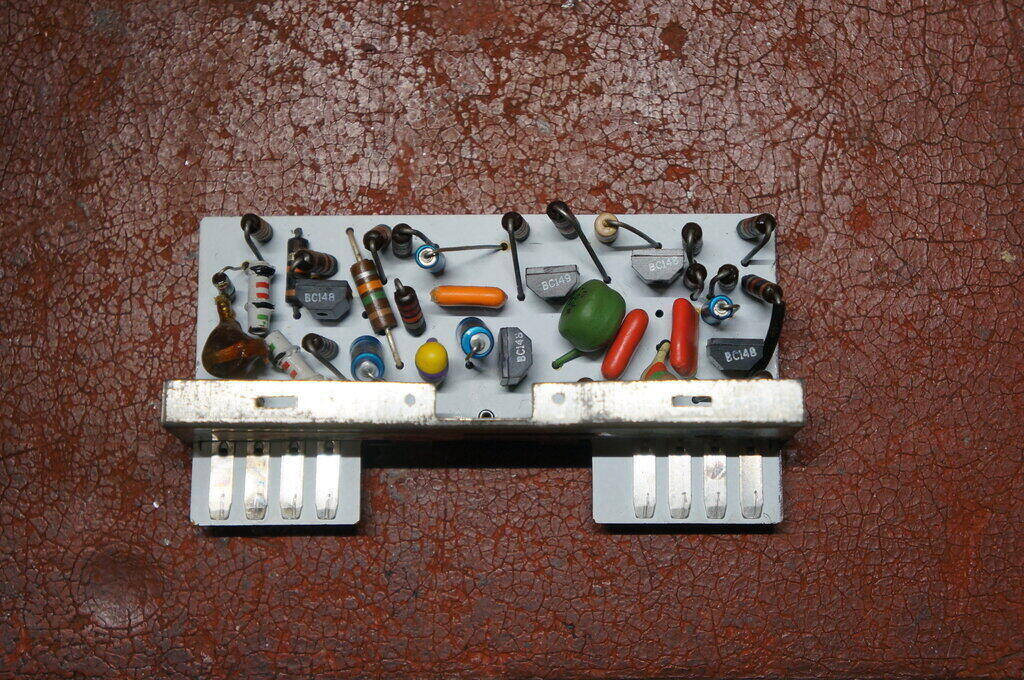
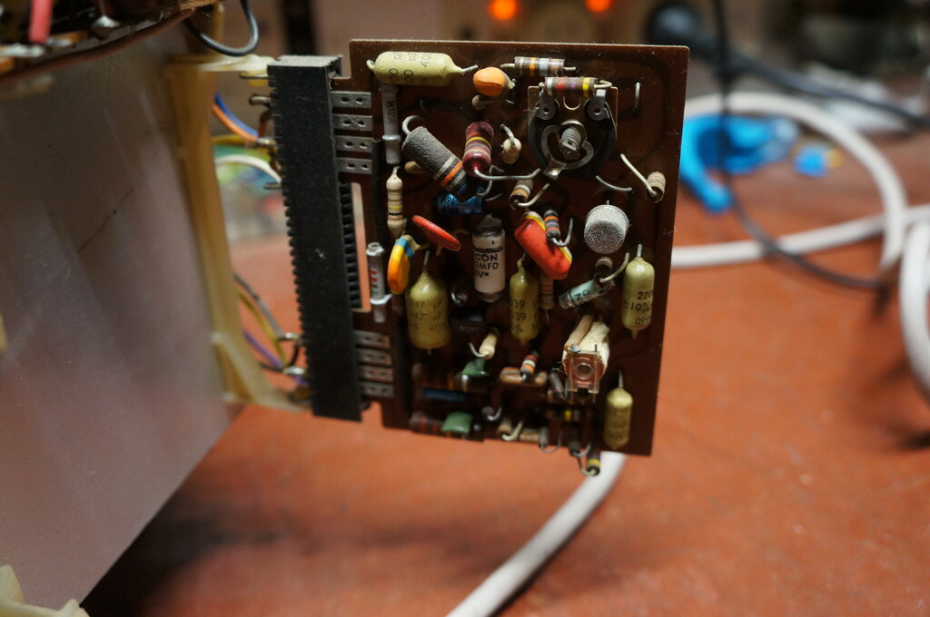
Inside the ZJ002 module.
Vertical Oscillator and Output ZV001.
The only active component in this module
is the 6GV8/ECL85 triode pentode valve. The circuit is conventional, although
complicated because of the waveshape correction, necessary with 110 degree
deflection. In the usual way, the triode functions as the oscillator (at
50Hz), and this drives the pentode as the output stage. It uses a multi-vibrator
circuit which eliminates blocking oscillator transformers. Positive feedback
from the pentode plate appears at the triode grid, causing it to oscillate.
Height stabilisation is provided by the
VDR (voltage dependent resistor) R459. As usual, the oscillator plate is
fed from the B+ boost source, since the higher voltage provides more of
a constant current source through the charging circuit (R458 and C453).
This provides a better sawtooth waveform, since the capacitor charges more
linearly than it would with a lower value of series resistor. Height is
adjusted by varying the supply voltage to the charging resistor.
The thermistor, R473, in series with the
B+ to the output transformer stabilises height as the set warms up.
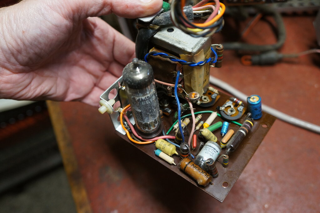
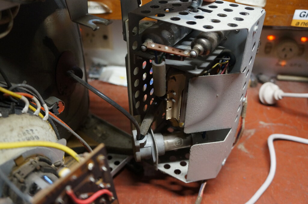
Frame oscillator/output model is easily removed. Note the Ducon
paper condenser (C450).
Power Supply ZP001.
As is typical of Australian design, an
isolated transformer power supply is used with full wave rectification.
Valve heaters are in parallel fed from a 6.3V winding.
The transformer is a C core type. Bridge
rectification is used for both HT and LT supplies. This simplifies transformer
design because only half the number of turns is required compared to a
full wave centre tap design.
Resistance capacitance filtering is used
for the main HT rail of 240V, and this is further filtered to provide 190V,
225V and 235V supplies.
The low voltage supply uses an AC187 germanium
transistor as a dynamic filter, to produce a 12V rail for most of the solid
state parts of the set. The exception is the video output and horizontal
oscillator sections. While there is a trimpot to set the 12V rail, it isn't
actually regulated, since reference voltage is merely a divided down portion
of the unregulated 240V supply. It is a curious thing why a 12V zener diode
was not used instead of the trimpot.
Power supply module.
Phase Comparator and Horizontal Oscillator
ZH001.
TR502, a BF178 is the horizontal oscillator
which drives the 6CM5 output valve. TR501 operates as a reactance control.
The control voltage for this comes from the two diodes D501 and D502 which
are the phase comparator. It is the standard circuit whereby the sync pulses
are used as a reference, and compared against a sawtooth voltage obtained
from the line output stage.
The sync pulses cause the diodes to conduct,
so that when fed with a sawtooth waveform, the resultant output will be
positive or negative going, depending on how far up or down the ramp it
is when they switch on. This error voltage shifts the horizontal oscillator
frequency so that it runs at the same frequency as the sync pulses.
The horizontal hold control provides an
offset to the error voltage so that the horizontal oscillator can be brought
into locking range. The supply to the reactance stage is stabilised by
a VDR, fed from the B+ via R523. Because of the high peak to peak voltage
required to drive the 6CM5, TR502 is also operated from the B+.
Horizontal oscillator and AFC module.
Horizontal Output ZH002.
This is completely standard circuit using
three of the most common Australian TV valves; 6CM5/EL36 output, 6AL3/EY88
damper, and 1S2/DY86 EHT rectifier. The 6CM5 is stabilised with a VDR,
R552. A negative voltage appears across the VDR since it's fed from the
line output transformer via C554. In the normal way, the 6CM5 is biassed
from the negative voltage which results from grid current flowing. The
stabilising circuit allows the negative voltage to be increased beyond
this, so that the plate current, and thus width and EHT can be automatically
reduced or increased as necessary. The result is constant width and EHT
over a reasonable range of picture brightness and mains voltage fluctuations.
So how is this negative stabilising voltage
developed when there's no diode? The VDR is after all a symmetrical device.
Indeed, with ordinary AC, there would be no DC output because the VDR would
conduct on both the negative and positive parts of the cycle.
However, when the waveform is asymmetrical, consisting of positive pulses
only, we can see that rectification will occur.
Line output module. 6CM5 and 6AL3 at the top.
Sound IF and Ratio Detector ZF003.
The 5.5MHz sound IF is fed into the module
via the transformer consisting of L201 and L202. From here, the signal
is amplified by TR201 and TR202, the latter also functioning as a limiter.
TR202's collector load is the ratio detector transformer T203.
From here, the FM signal is demodulated
by diodes D201 and D202. Audio output appears at pin 2.
Sound Output Stage ZA001.
This particular audio amplifier circuit
was used in a multitude of Philips products at the time, so it's not surprising
to see it here. It is a four transistor class B circuit which is completely
conventional. The output is a complementary symmetry type of circuit which
eliminates the otherwise required output transformer. The output transistors
are the well known AC187 and AC188. These are driven by and AC128, another
germanium type. Output bias is temperature stabilised by a thermistor.
This is necessary since germanium transistors are affected by temperature
more so than silicon types. Power supply is not 12V, but instead the 16.5V
unregulated supply. The output circuit has an inherent degree of hum cancellation,
so a regulated supply is not needed, and additionally, extra output power
is obtained from the higher voltage.
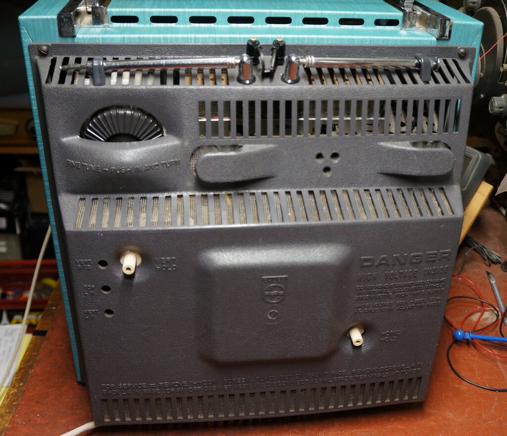
Back of the T284.
If you should acquire one of these Philips
sets, you will find it very easy to work on. Just be prepared to replace
lots of IRC resistors and some of the blue electrolytics. But, having done
that, the reliability will be exceptionally good.
As far as this particular set is concerned,
I found that once the cover had been put back on, that there is a heat
sensitive fault - the sync problem gets worse as it warms up. Ultimately,
the resistors will have to be replaced.