Not a set for the inexperienced technician!
Not a set for the inexperienced technician!
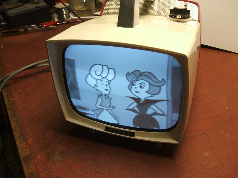
This set came to me for restoration from
a fellow TV collector, with the complaint that it stopped working. It's
very typical of the early 60's futuristic "Space Age" type of design, so
common with Japanese sets of this era. From experience with similar sets,
I imagined PCB's full of electrolytics having gone low in value, and the
possibility of failed germanium transistors.
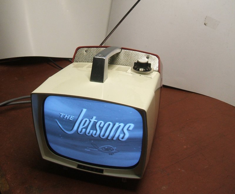
I have in my collection one similar age
6" Sharp set, a TRP-601, which I restored some years ago, and I have also
worked on one of the 5" Sony sets from this era.
As is typical of this kind of set, it can
operate from mains or 12V from a rechargeable battery. Part of the back
cover was missing, so I had nothing to identify the model with. Looking
through my JR manuals for 8" Sharp sets showed up TRP-803 and TRP-804.
A google image search showed TRP-804 virtually identical to what I had.
The differences were a different speaker grille, and the cabinet back and
power cable entry were different. At this point I assumed it was a TRP-804,
not having seen any pictures of the TRP-803.
The set had obviously been well used,
with labelling rubbed off near the fine tuning knob. Something bodgie had
been done with the mains lead; a length of twin flex went into the set
directly, even though there was a two pin mains input socket.
Also obvious was that it was made for
the European channels; 1 to 12. Stickers had been put on the channel knob
for the local channels 2,7, and 9. While the Australian and European (except
French) TV systems were the same, the channel designations were not. However,
the band 3 channels are the same, albeit with different numbering. Europe
did not use band 2 for TV, which means the set cannot receive Australian
channels 3, 4, 5, and 5A. The band 1 channels are close enough. Many European
sets were sold in Australia without modification, but they were limited
in use for some regional areas. Interestingly, the power supply is for
240V and not 220V, which means that whoever was importing these sets was
deliberately intending them for to be for sale in Australia; i.e., not
just a one off set brought in by an overseas traveller or immigrant.
Getting it Apart.
Of all the sets I have serviced, this
would be the worst I can recall for service access. The plastic cabinet
comprises three sections. First is the front piece which holds the CRT.
There is the middle section which covers the PCB's and chassis, and the
back cover.
The back cover comes off easily enough,
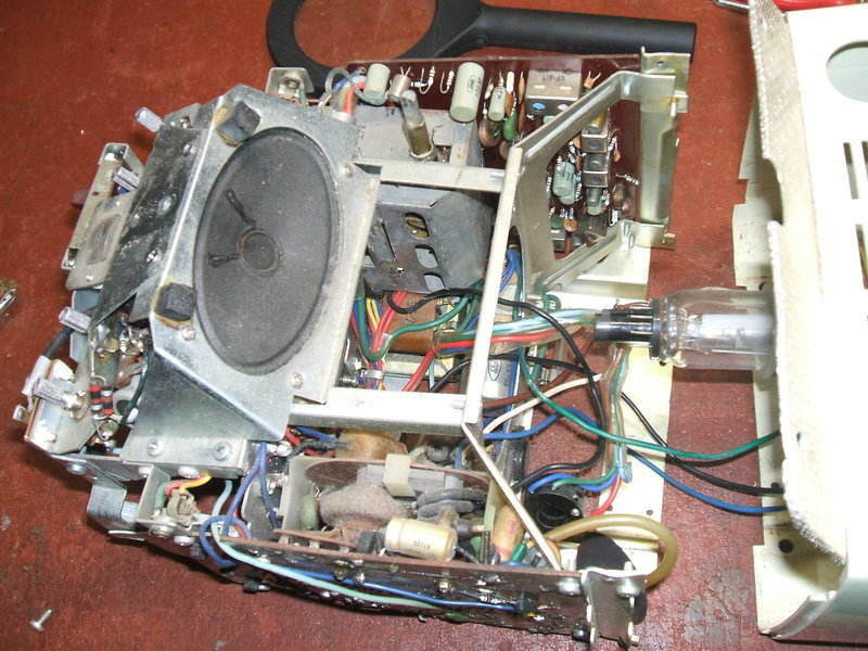
but only reveals the power supply, speaker, and controls. The power supply
is a plug in module and slides out with no tools.
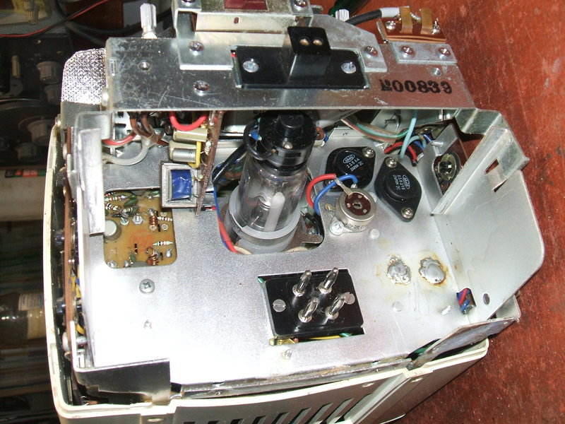
Back cover and power supply removed. Line driver and output transistors
visible top right.
The front also comes off easily enough, and apart from the short EHT lead, the front with picture tube can be pulled forward by a reasonable amount. The yoke and CRT leads are quite long enough for this without having to disconnect them, and provided the EHT lead was extended, the set can be run like this during servicing.
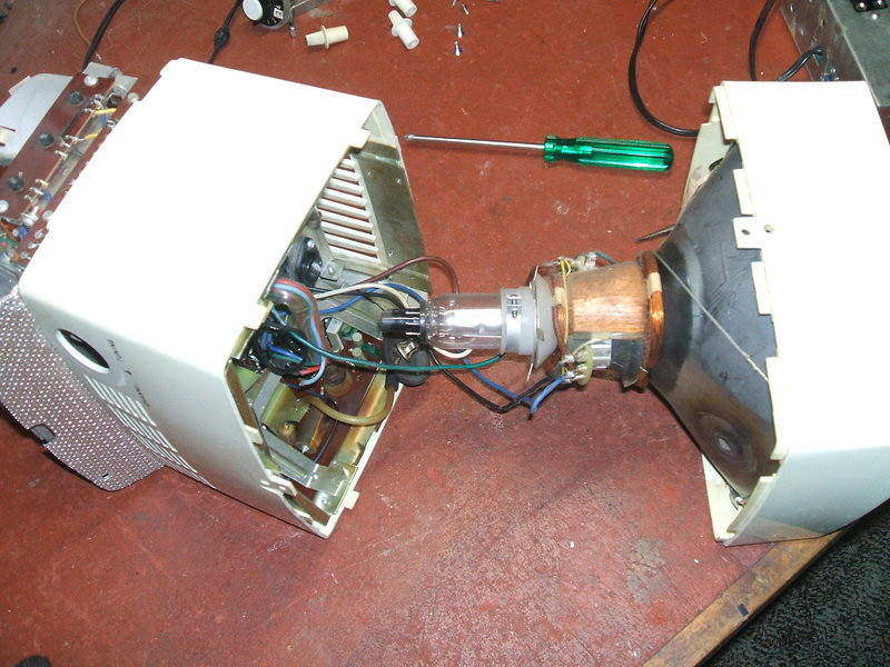
Front and mid sections separated.
There are many screws to be removed before
even getting this far; the handle and feet need to be removed before even
thinking about splitting the cabinet apart.
The challenge now was to remove the mid
section of the cabinet - for this was covering the two PCB's. It couldn't
go back because the speaker was in the way. It couldn't go forward because
of the chassis construction. At this point I was beginning to see how appalling
the mechanical design of this set was. Everything was constructed around
multiple brackets held together with multiple screws. It was like everything
was an afterthought - want an earphone socket? Mount it on its own bracket...and
so on.
Needless to say, there's nothing useful
about this set on the internet, and I didn't particularly want to order
the Sams Photofact for it, given the expense and postage delay. One forum
that did mention it had someone say the mid section had to be split to
remove it. That seemed a bit drastic!
Eventually, I worked out that by removing
one of the brackets at the top of the chassis front, the mid section of
the cabinet could slide forward towards the CRT.

Removing the top bracket (6 screws) will allow the casing to slide
forward.
All is finally revealed!
The two PCB's swing out once more screws are removed.
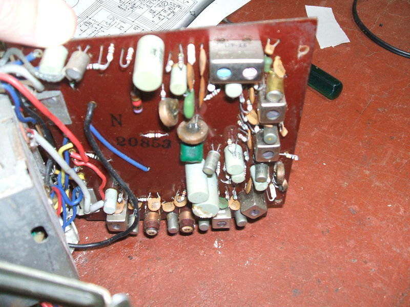
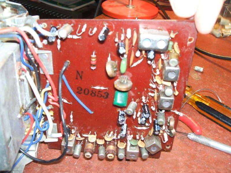
Small signals board with original capacitors. Note the electrolyte
leaking from the large capacitor near the bottom.
Timebase board with original parts.
Restoration Begins.
I made a list of required capacitors,
noting there were also some paper types in the line output stage, and gathered
them from my stock of parts. Next I settled down to a couple of days of
replacing capacitors. This wasn't as easy as it should be.
The PCB did not have any component overlay
printed on it which made finding the right points to unsolder difficult.
I used a penlight shining through the board which helped. The component
leads had all been folded down before soldering which adds to
the difficulty of removing. And, as is
not atypical of PCB's of this age, it's easy for the tracks to lift if
heated for too long.
I wasn't impressed with the EHT lead attachment
to its terminal on the line output transformer sub-assembly. It was very
delicate, and I could see that it had broken off been reconnected in the
past, as had the CRT EHT connector clip. Obviously, this was not the first
time the set
had been apart. Since the EHT lead is
so stiff and short, any movement is transferred directly to the terminal
on the line output transformer sub-assembly. Another thing that caught
my attention was a blue wire broken off the CRT base - this I presume is
what was behind "it stopped working" complaint.
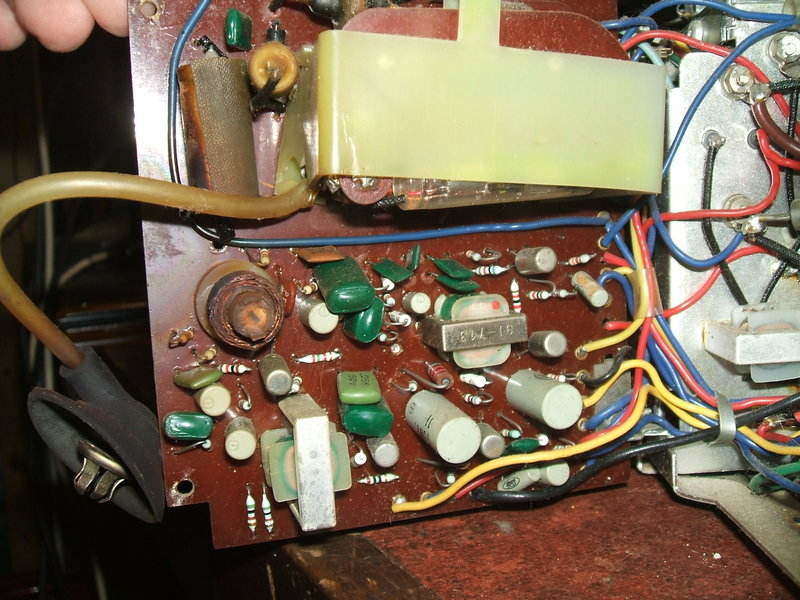
New capacitors on timebase board.
While replacing the paper capacitors, I
found the reason for the set's previous servicing. The damper diode had
been replaced. An OA210 had been used, which while common in the 60's,
isn't really ideal for line frequency operation. I used a 3A fast rectifier
diode to replace it.
Getting to some of the tagstrip connections
to replace the paper caps was difficult, but the job was done without too
much damage.
On the second day, I started on the small
signals board.
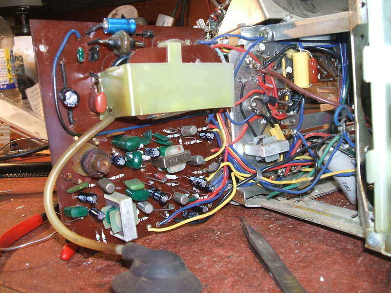
New capacitors for the small signals board.
Once this was done, the set was ready for
testing. It was more convenient to use a bench power supply, partly because
the set was much easier to move around without the weight of its own power
supply, and also so I could monitor the current draw.
There appeared to be a virtual short circuit
on first power up. I quickly realised I'd installed the new damper diode
the wrong way round, as I'm more used to working with positive supply rails
and NPN transistors. Reversing it fixed that, and the set drew just a bit
over one amp, and we had a raster!
However, a number of problems were evident
which I was not expecting. At this point I'll digress to the circuit design
first so the subsequent description will be clearer.
The Circuit.
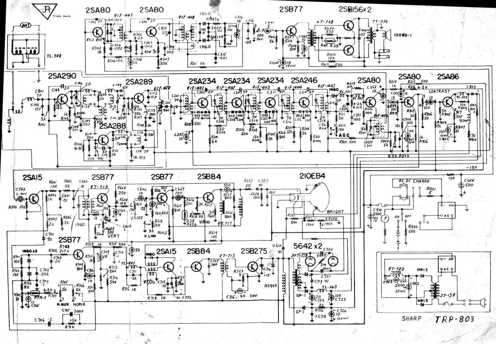
The design is quite straightforward and typical of the first generation of solid state sets.
Power Supply.
Unlike later designs, the power supply
is a simple capacitor and choke filtered design, with no regulation.
The choke is resonated at 100c/s with a 30uF capacitor (C903) to improve
filtering. The power supply provides a nominal 12V. It also is used to
charge the battery via a 5R resistor. There is nothing to control the charging,
so hopefully the user will turn off the charging once the battery is charged.
A simple uncalibrated meter is connected across the power supply, which
would give an indication of when the battery has reached full charged.
Note that because of the PNP transistors, the supply rail is negative.
That is, the set has a positive earth. It appears the battery hangs from
the back of the set on a hook provided. There is a two pin socket into
which it connects.
Front End.
The VHF tuner uses three transistors;
RF amplifier, mixer, and oscillator. There is no AGC applied to the RF
amplifier.
The video IF amplifier consists of four
transistors, and being germanium types, they're neutralised with 5pF capacitors.
The IF is detected with a 1N60 diode. After filtering, the video signal
feeds an emitter follower. Before the video gets to the next stage, the
5.5Mc/s sound is extracted by a transformer in the emitter circuit. This
would also work as a sound trap.
The sound IF is amplified by a two stage
neutralised amplifier, and then feeds a conventional ratio detector to
obtain the base band audio. The audio amplifier is a conventional three
transistor, transformer coupled design. The output stage is a typical class
B push-pull type with thermistor stabilisation. Two earphone sockets are
provided; one operates in parallel with the speaker, and the other disconnects
the speaker when in use.
It is interesting to note that despite
the PNP transistors, the supply to the front end is positive 12V. My guess
is this was done so that one side of the coils can be directly earthed
for stability.
Video & AGC.
Because of the low input resistance of
transistors used in the usual common emitter mode, an emitter follower
is connected after the detector diode. This provides current gain, but
not voltage gain, to drive the next stage. This is a normal common emitter
amplifier, but the collector load resistance is actually the contrast control.
The low impedance here allows this kind of control without needing frequency
compensation. That is to say, stray capacitance has minimal effect. From
the wiper of the contrast control, the video proceeds to the output stage,
operating from a supply of -70V. This voltage is necessary of course to
fully modulate the picture tube.
Only one stage of the video IF amplifier
is controlled by AGC; the first transistor. The AGC voltage comes from
the collector circuit of the video emitter follower stage. Since the emitter
current will vary with the output level of the detector, so will the collector
current. The voltage drop across the collector resistors R215 and R216,
will thus vary with signal strength. A portion of this voltage biasses
the base of the first video IF amplifier.
As video signal increases, the 2SA80 emitter
follower is reduced in current, causing the collector voltage to rise.
This increases bias on the first video IF transistor 2SA234, causing it
to reduce in gain. Unlike valves, transistors are often operated with forward
AGC; that is, an increase in collector current reduces gain. The video
is filtered out by C222, C223, and C205, so that only a steady DC is used
to control the gain.
Frame Oscillator and Output.
A simple one transistor (2SA15) sync separator
is fed from the first video amplifier. The transistor is self biassed by
the video signal so that it conducts only on the sync tips. The frame oscillator
is the blocking oscillator type, based around a feedback transformer. Sync
pulses are filtered so only the frame sync pulses are fed into this transformer.
The sawtooth voltage feeds the first amplifier stage by a simple series
resistor type of height control. From the 2SB77, the voltage feeds the
2SB84 output stage. It is choke coupled to the deflection yoke. Blanking
pulses are fed to the CRT via R627 and C727 so that the retrace is not
visible during the vertical blanking period.
Line Oscillator and Output.
Again, this is typical of transistor practice.
A 2SA15 blocking oscillator feeds a 2SB84 driver stage, which is then transformer
coupled into the 2SB275 output stage. Drive for the 2SB275 is set by the
3R rheostat. Positive oscillations during retrace are damped by the shunt
diode. Note that unlike valve circuits, the damper diode is not used in
an 'efficiency' or 'boost' circuit. It should be pointed out that this
set is using only one output transistor, which is what those familiar with
modern sets would expect. By the time the TRP-803 was developed, transistor
voltage ratings were high enough to do this. Previously, two transistors
in series had to be used, as per the TRP-801, to get sufficient voltage
rating.
The AFC circuit is quite conventional,
with a sample of the line frequency taken from the line output transistor
collector, and compared to the incoming sync pulses with the two 1N60 diodes.
An error voltage is produced, which is amplified by the 2SB77. This in
turn controls the base current of the oscillator, and thus its frequency.
Since solid state diodes did not have
sufficient voltage ratings at this time, the EHT is rectified by two subminiature
valves, type 5642. A voltage doubler circuit is used, which means the EHT
overwind only needs half the amount of turns as would be required if only
one rectifier was used.
As is typical, the diode heaters are fed
from windings on the line output transformer core, but this is not actually
shown on the circuit. EHT is 8kV.
As mentioned before, the line output transformer
also provides a -70V supply for the video output stage, and positive 12V
for the IF stage and tuner.
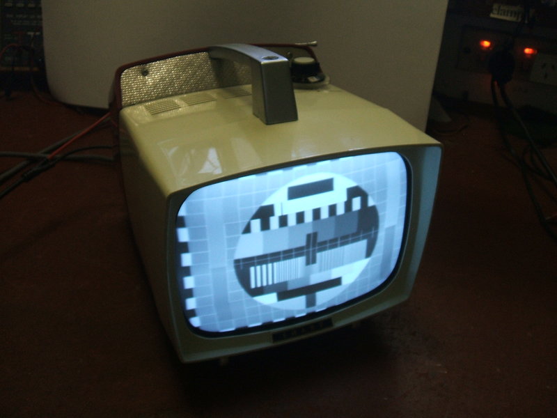
The picture tube is an 8" (21cm) 210EB4. It is 90 degrees and has a 12.6V heater.
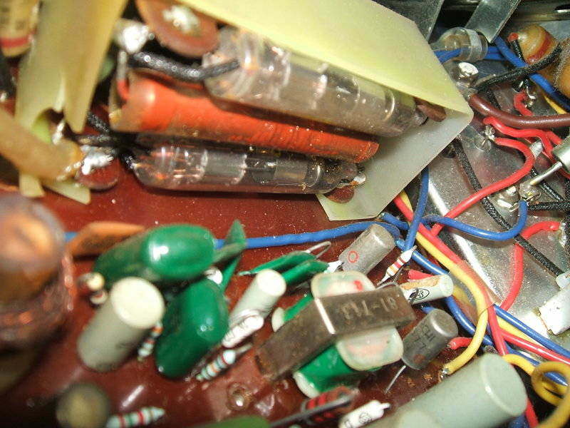
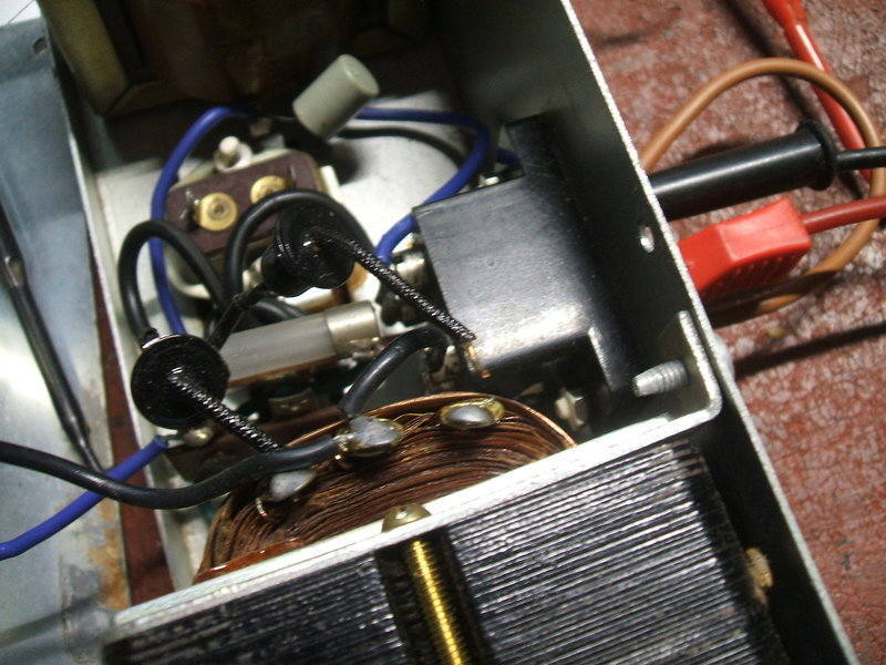
EHT rectifier diodes. Note the 3M resistor in between. The EHT connection
can also be seen.
I checked the EHT in case it was too high - it was 8kV which is about right for an 8" tube. There was no option but to improve the insulation of the capacitor which I did with silicone sealant. Perhaps it was EHT arcing which killed the original damper diode. I can't see how the set could have operated for all these years like this. Anyway, the EHT arcing stopped, so I could safely move onto the next problem.
Insufficient Height.
The vertical height was way down; about
half what it should be. This was odd since I'd replaced all the capacitors
on the timebase PCB. However, one capacitor I hadn't replaced was the 500uF
coupling the output choke to the yoke, I hadn't replaced it since high
values like this are normally reliable. Not surprisingly, bridging it with
a new one didn't increase the height. A check on the CRO using the waveforms
shown on the TRP-804 circuit diagram indicated that the amplitude was indeed
slightly down at the output stage.
It seemed unlikely that the oscillator
or amplifier transistors would be faulty; it's rare for a transistor to
fail with low gain. The oscillator output voltage seemed OK, in fact a
little more than specified.
One way to see if the amplifier and output
stage could actually fully deflect the beam would be to connect an external
function generator instead. This I did by disconnecting C604 from the height
control and feeding in a sawtooth at 50c/s. No problems in obtaining full
deflection, so it seemed the 2SB77 just needed more input. What if we just
bypassed the height control and series resistor? Well, that certainly did
things; a 6.8K resistor bridging that part of the circuit brought the picture
up to full height. I could have taken the easy way out and permanently
soldered the resistor in, but that isn't finding what has caused the fault.
And, I don't like to modify circuits to make them work unless there's good
reason to do so.
The height control itself was OK, so that
just leaves R609, the series resistor.
I must point out that until this time,
I'd been using the TRP-804 circuit for working on the set. While tracing
the circuit to find R609, I was surprised to see it was 10K, and had been
soldered to the track side of the board. A strange thing to do, since there
was space for it on the component side. The TRP-804 shows this resistor
as 5K. When I installed a 4.7K resistor in place of the 10K, we had full
height! This was bizarre. How could the set have been used with insufficient
height for all these years?
While searching through my manuals, I
discovered I did have the TRP-803 circuit. And here the resistor is shown
as 10K. So it really was the TRP-803 I was working on, not the TRP-804.
But it remains a mystery why one model specifies 10K and the other 5K.
Electrically the sets appear to be the same otherwise. There is one interesting
thing; a triangle symbol next to R609 on the TRP-803 circuit. This suggests
it might be a 'select on test' value. It would appear 10K was sometimes
too high, hence the 5K in the TRP-804. It still doesn't solve the mystery!
Over the period of soak testing the set, the height has remained perfect
with no sign of intermittent or otherwise faults.
Line Centering.
Feeding the Philips PM5544 test pattern
into the set, it was obvious that the picture centering was not as it should
be. There was not enough adjustment in the centering magnets to shift the
picture to the left, without causing neck shadow. I made sure the line
oscillator was adjusted correctly - it's often possible to shift the picture
using the line hold control over a small degree, but unless the setting
is correct, sync will be lost soon as the channel is changed or the set
next turned on.
All I could do was to electrically shift
the picture. The way to do this is change the phase of the AFC feedback.
In this set, that involved adding another 820pF across C707. It's true
that the shift would have gone unnoticed on ordinary program material,
but was obvious with the test pattern. One would think the set was aligned
in the factory with a test pattern, so this should have been evident at
the time of manufacture.
Line centering not perfect, but a lot better than it was.
The line deflection coils are shunt fed from the line output transformer with no capacitor, so there could be some DC causing the shift, but this should be factored into the design.
Video in the Sync.
While the picture geometry was now acceptable
for the type of set, there was one remaining fault which had been evident
all along. A severe flag waving was visible at the top of the picture,
and depending on scene content, vertical objects which should be straight
were anything but. Evidently, the sync pulses still contained video information.
The sync separator is very simple with one transistor. One thing I suspected
was the transistor itself being an old germanium type which could be leaky.
Rather than try another germanium type, I put in a silicon BC559, as I
felt this would give a more definite switching action, especially as silicon
types have a higher base voltage (600mV vs. 250mV of germanium). Indeed,
it was noticeably better, but still not acceptable. I've seen one transistor
sync separator circuits work perfectly well in other sets so it should
be possible to make it work. But playing around with the input capacitor
and base resistor just didn't do anything useful.
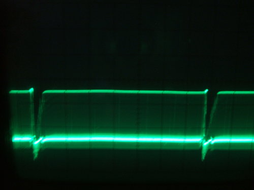
There was a lot less video in the sync with the BC559, but still
a gap where the line pulses were being lost after the frame sync pulse.
At right is the improved sync waveform with modified circuit.
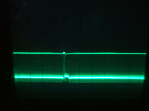
Looking at the waveform at the sync separator
transistor collector showed pretty good sync pulses except for one thing.
There was a strange gap just after the frame sync pulse, where the line
sync pulses were missing. No wonder it was flag waving at the top of the
picture.
With the terrible service access, and
not easily being able to identify the components on the PCB, working on
this set had become a rather unpleasant experience. I really wanted it
fixed and gone with it taking a lot more time than it should have. Now,
I was contemplating one thing that would get me out of trouble; put in
an LM1881 sync separator IC and be done with it. The modifications wouldn't
be too great, and provided the sync and video polarities were suitable,
it would solve the problem. At this stage I was no longer worried about
doing modifications - I just wanted to get a stable picture. However, it
would take several weeks to order an LM1881, and would further delay its
repair..
Seeing as there was video in the sync, I checked one other thing. The black level of the video signal should be constant and flat, when looked at on the CRO. In this set it wasn't always. Depending on scene content, there was some tilt. This is a common sign of an insufficient AGC time constant in sets using simple AGC - as this set does. Some improvement could be had by increasing the AGC filter capacitors, but it didn't completely get rid of the problem. Adjusting the AGC control helped, but again we see one of the problems with simple AGC; the AGC voltage is dependent to some degree on scene content.
One set using a one transistor sync separator
is the Pye T29/T30. I had a quick look at the circuit and noted it used
a different method for biassing. Instead of a resistor between base and
earth, the T29/T30 has a resistor between base and collector. That is,
it has bias even with no video signal. So, lets give this a go before we
go down the LM1881 path. And that was it! To find the optimum resistance
value, a pot was connected between collector and base and adjusted for
a good sync signal with little video. Importantly there was no gap after
the frame pulse. The other thing I was suspicious of was that the 1uF input
capacitor was too high, causing a too long of a time constant, and the
loss of line pulses after the frame pulse. I used a 0.1uF with the new
circuit and this fixed that problem. So, the final modification was to
use a BC559 for the transistor, remove the 12K, change the 1uF to 0.1uF,
and connect a 68K between collector and base. The new sync separator tolerates
the tilt in the black level, so I didn't have to modify the AGC as well.
Finally the stress was over - well, almost!
Getting the set back together in its cabinet required a bit of dexterity and careful placement of the wires to the CRT. The EHT connection is particularly awkward and fragile, and I'm not really happy with it. A lead carrying 8kV pushed up against solid state circuitry isn't the best aspect of design.
Power Supply.
The final part of this tale of woe was
actually quite relaxing in comparison to the rest of the set. Until now
I'd been running the set off my bench supply. Now, when I tried it back
on the original power supply, I was surprised to see a dim shrunken picture.
The volts were down; 10.4V. There's not
much that can go wrong given the simplicity of the power supply. The logical
thing to check first is the filter capacitors. Bridging these did increase
the voltage, but not by much; only 300mV.
The transformer secondary is 12.5-0-12.5V.
When rectified, that should be up around 17V. Alas, there was only 11.5V
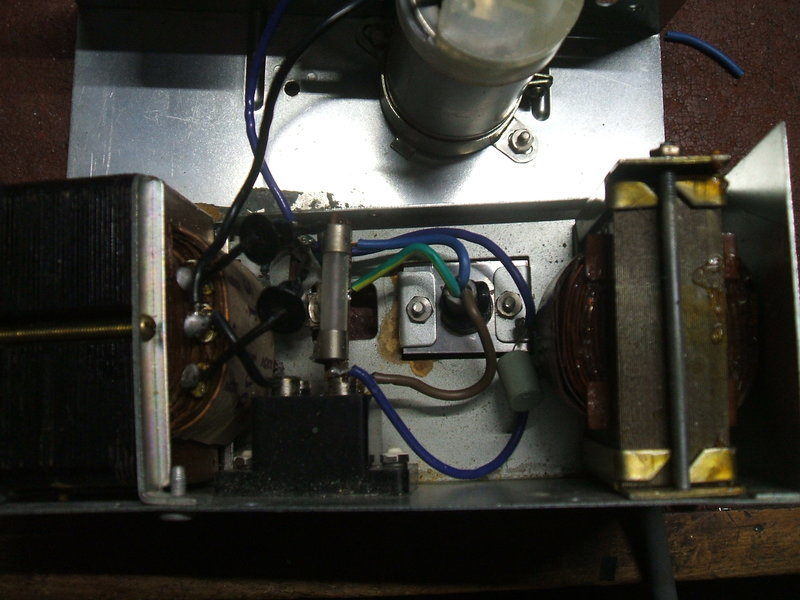
on the first filter capacitor. I suddenly noticed one of the rectifier
diodes felt loose at its connection on the transformer tag.
Classic dry joint. Look at the diode lead on the right - bare copper.
The power supply was working in half wave.
The diode lead had never seen solder. Here
we had the classic dry joint, hidden by the solder on the transformer tag.
So, with the power supply operating in half wave, it's no wonder the output
was low. Restoring a proper soldered connection also restored the volts.
Now back up to 12.5V, the set was working
well. In fact, the filtering is remarkably good considering there's no
active components.
The last job on this set was to deal with something I wasn't happy about from the start. At some point in the set's past, the mains lead had been lost, or perhaps the plug that goes into the set failed. The lead had been connected directly into the power supply instead. Thankfully, whoever did it removed the connections to the input socket, so the bare pins wouldn't be a shock hazard. Two things I wasn't happy about was that the way the lead had been fed in, meant is was being partially crushed by the bottom of the plastic cabinet. Also, it was only twin flex. Having seen how close the mains connections inside the power supply are to the case and the 12V side of the supply, I felt it should be earthed.
New mains input is much safer.
I made up an aluminium plate to take place
of the old two pin socket, and installed a cable clamp grommet for the
new three core flex.
Job done at last!!
A minor adjustment was to tweak all the sound IF transformers to reduce the frame buzz. There is some buzz at very low settings of the volume control, but this is coming from the frame output stage. No doubt it's due to close coupling of the audio circuitry or common earth connections, etc. But, by this time I was over trying to redesign the set for absolute perfection. The buzz is not audible at normal volume settings.