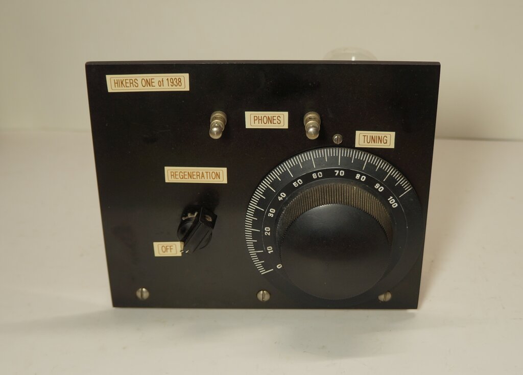
Replica of a Hiker's One.
Replica of a Hiker's One.
To vintage radio enthusiasts in Australia and New Zealand, the "Hiker's One" name refers to a one valve regenerative receiver, operating from a low B+ voltage; typically 6 to 13.5V. The attraction was of course, that the otherwise necessary (and expensive) 45V B battery was done away with. Instead, a cheap 9V bias "C" battery could be used, or a combination of similarly inexpensive torch cells. The valve filament was powered from a 1.5V No. 6 dry cell, or a couple of paralleled torch cells. Low voltage B+ operation was achieved by using a type 49 valve in space charge mode.
Basic Operation.
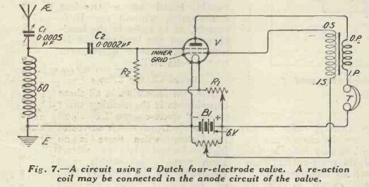
In simple terms, a valve with two grids
is used (termed 'dual grid', 'double grid, 'bi-grid', 'bi-grille', etc.).
The first grid is biassed positive, to force sufficient electron flow to
occur from the cathode. Enough electrons reach the plate to allow it to
function at a lower than normal voltage. The signal is fed into the second
(outer) grid, and the valve functions as a triode. While it might appear
that one should call such a valve a 'tetrode', the difference is that both
grids control electron flow. The second grid in a tetrode is designed to
function as a screen.
Space charge operation was largely an
experimental novelty in the 1920's, as will be described further on. The
Hiker's circuit briefly revived it in the 1930's, with its final application
in the late 1950's, for car radio use.
Origin of the Hiker's.
Many articles on the Hiker's circuit claim
that the design originated from a Popular Mechanics article in 1936. In
fact, the circuit was first presented by a Canadian amateur in QST for
October 1935. It was a two valve receiver, with a 49 operating as a regenerative
detector, and a 30 operating as an audio amplifier. However, it would be
true to say that the Popular Mechanics article is what popularised the
design, since QST was exclusively an amateur radio magazine.
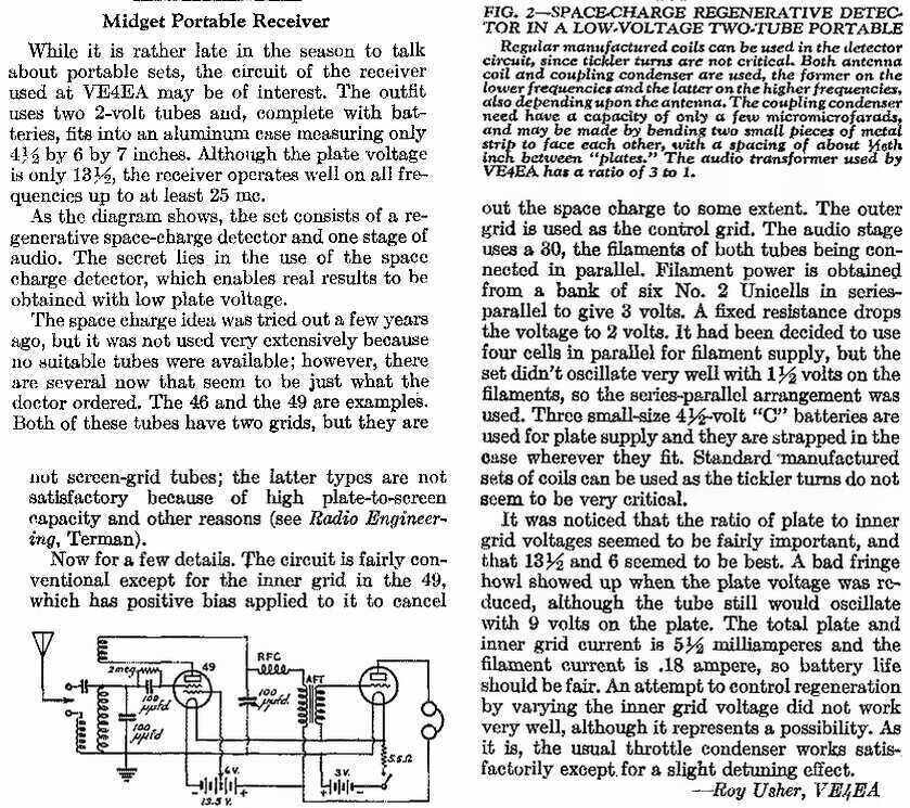
From QST, October 1935. This appears to be the first recorded use of the 49 in space charge mode.
A modified version of the circuit, without the audio stage, was presented as a constructional article by Popular Mechanics for September 1936, its claim to fame was that only six 1.5V cells were required to power the whole set.
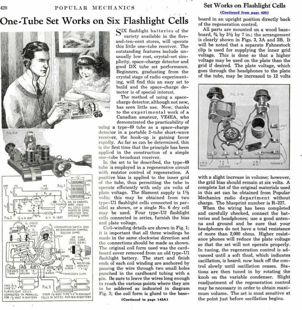
From Popular Mechanics, September 1936. For the original article
see https://archive.org/details/PopularMechanics1936/Popular_Mechanics_01_1936/
Besides the low B+ voltage, the other novel feature was the use of the rather unusual type 49 valve. By operating this so called 'dual grid' valve in space charge mode, enough plate current would flow at 6V for the circuit to function.
Even though the 49 has a 2V heater, the Hiker's circuit operated it at 1.5V for convenient use of dry cells. Electron emission is still adequate at the low plate current.
In this part of the world, the Popular Mechanics circuit was promoted by the Lamphouse electrical store in Wellington, NZ. They gave it the "Hiker's" name and sold it in kit form. The circuit was slightly modified in 1939 to become the "Improved Hiker's", and was a very popular kit. In fact, one valve receivers were always popular in Australia and NZ, right up until the transistor era. We didn't have the affluence of the middle class U.S., and radio components were expensive. Such receivers built in a compact portable form also suited our outdoor lifestyle, hence the "Hiker's" name.
In more recent times, the well known NZ radio historian, Peter Lankshear, wrote an article on the Hiker's One for "Electronics Australia", October 1989.
Peter Lankshear's Hiker's One.
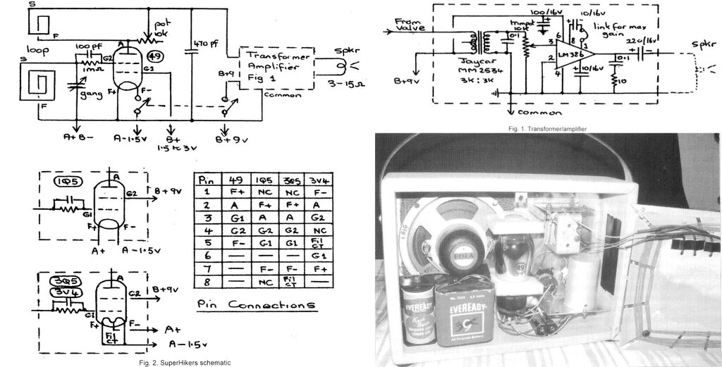
Portable loop aerial version uses IC amplifier.
A compilation of articles on the Hiker's One can be seen at another site here.
The 49 Valve.
Introduced in 1933, the type 49 was intended
for use as a class B output valve for battery receivers. The 49 is an unusual
'dual grid' valve with similar construction to a tetrode. The intention
was for class B operation, with two 49's used in push-pull. The two grids
were connected together, with the valve functioning as a high mu triode
operating at zero bias. In this mode, the output power would be 3.5W for
a 180V B+.
Alternatively, by connecting the second
grid to the plate, the valve would function as a conventional triode, which
could be used as a driver for the class B output stage. Connected this
way, the output power was 170mW.
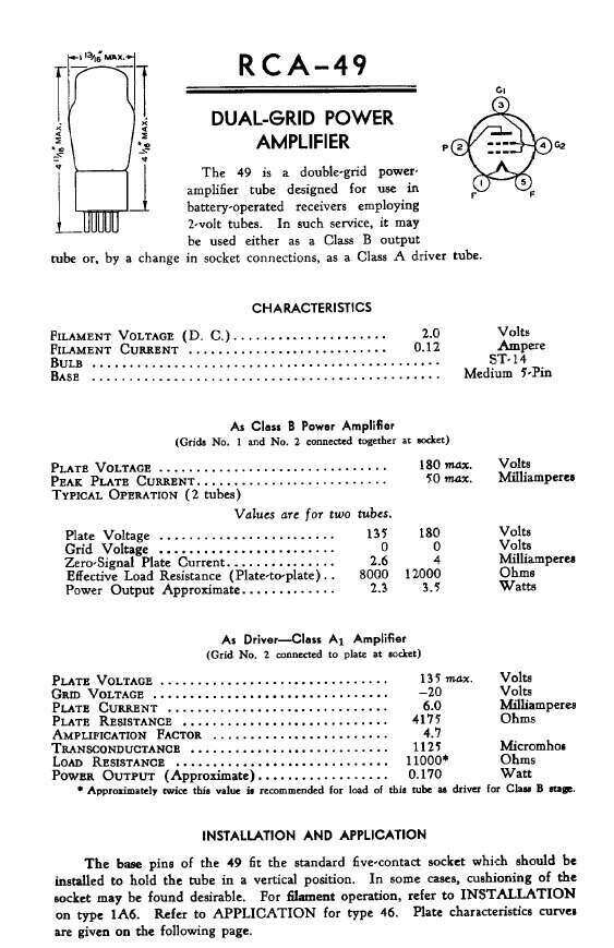
Data for the 49.
Although no doubt never intended by the manufacturers, the 49 could function in space charge mode, by taking the inner grid (closest to the cathode) to a positive voltage, and using the second grid as the control grid.
Obscure Valve.
I have never seen the 49 circuit in any
Australian publication of the period, which was no doubt due to a preference
for locally made valve types, of which the 49 was not. Battery class B
output stages instead favoured the locally produced 19 or 1J6 twin triode.
This valve too, ended up being used for
one valve battery sets of more conventional design, best known as the "Little
Jim". This name, first created by "Wireless Weekly", became famous for
successive twin triode one valve receivers.

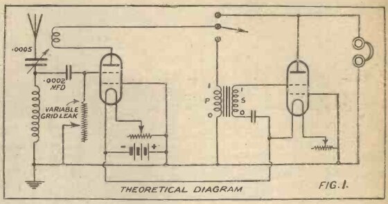
Early Space Charge Designs.
While it would be fair to say the 49 valve,
and 1935 circuit, promoted space charge operation, the concept is actually
much older, but had long been forgotten. Space charge operation was invented
by Irving Langmuir in 1913, and his patent shows a dual grid valve as a
simple amplified detector. Several types of dual grid valves were produced
in the 1920's, apparently intended for mixer circuits in early superhets.
I suggest reading the following article on The Valve Museum site, which
goes into quite some detail of the development.
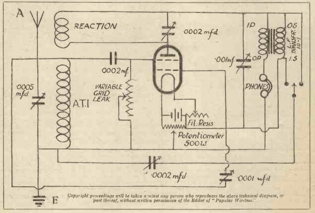
Popular Wireless "Unidyne".
Audio stage uses space charge circuit.
The May 31st issue concludes with a two valve set operating a speaker. One advertised kit supplier recommended Thorpe K4 valves, operating from 6V.
May 31st finishes with the two valve version operating a speaker.
Wireless Weekly, May 1924.
The criticism concerning the Popular Wireless
design came from the British "Wireless Weekly" for May 14, 1924. This issue
presented an article containing several low HT designs using conventional
triodes. It concludes with a space charge design operating from 6V, to
which a loudspeaking stage is then added of conventional design.
From the "Wireless Weekly" magazine, May 14, 1924.
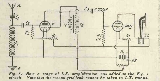
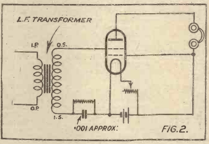
An addition of another valve to the previous circuit drives a speaker.
The limiting factor will always be no more than 6Vp-p into the speaker.
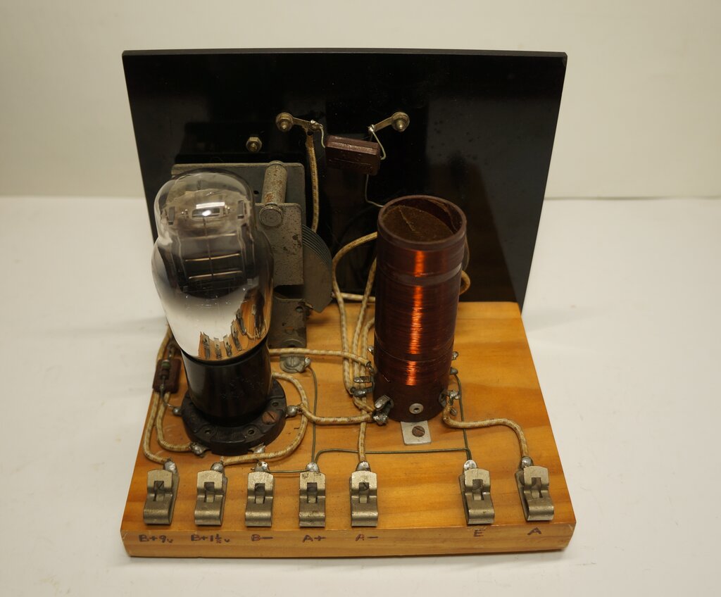
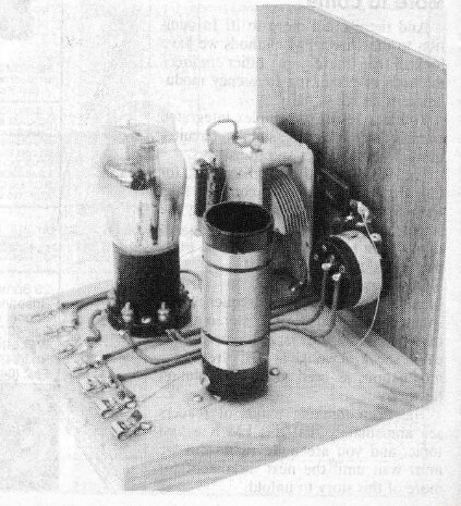
Rear view of the replica set.
A complete replica of a Hiker's One recently became available for testing, courtesy of fellow enthusiast Lance Neame (ZL3LAD). According to the annotation under the base, it had been assembled in 1989, by an unknown NZ constructor with the initials "PCM". The parts were all original, and of the period.
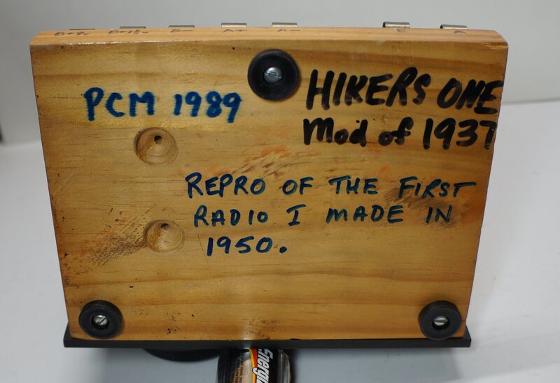
This set was built in 1989 from vintage parts.
This particular set was built according to the "Improved Hiker's One" design from the 1939 Lamphouse Annual mail order catalog.
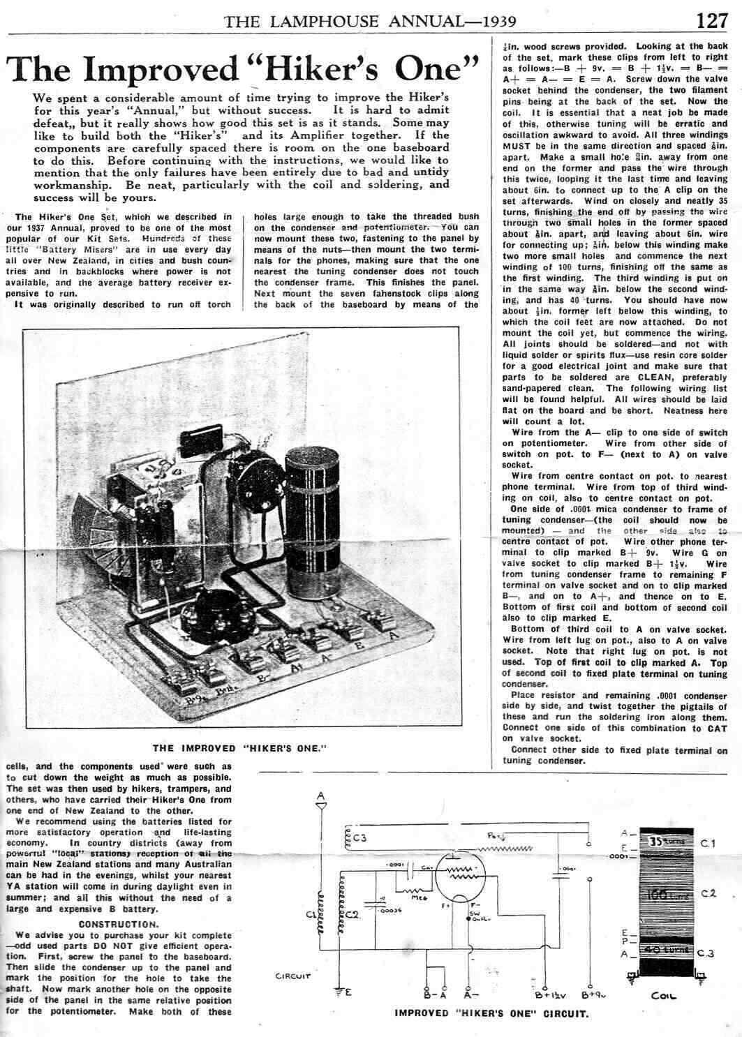
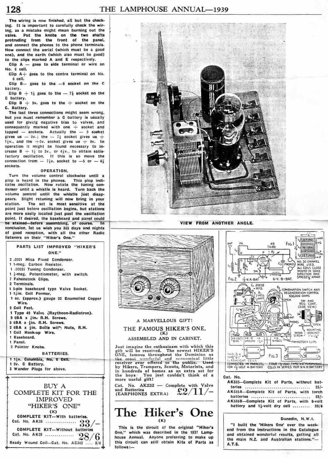
Lamphouse article shows both the Improved and original designs.
The only difference between the "Improved" and their original is the operating voltages. The original uses 6V for both grid 1 and plate. The improved uses 1.5V for grid 1, and 9V for the plate.
First Tests.
The first test was a disappointment. Volume
was poor along with difficult regeneration adjustment. Why Lamphouse thought
only 1.5V on grid 1 was an "improvement" is a mystery, because it was necessary
to apply at least around 4V for an acceptable volume level.
Having dealt with that, the regeneration
adjustment was critical because of an excessively high value of potentiometer.
It's specified as 500k, which isn't going to do much shunted across a low
impedance coil, except right at the low resistance end of the track.
This trend of specifying pot values 100
times greater than what they should be, really makes the sets difficult
to use, and no wonder people are put off regenerative receivers when they're
designed like this. This seems to have started with the Popular Mechanics
article. The original QST article uses a variable condenser.
Regeneration Control.
At least in this instance, the pot was
50k, but this is still at least ten times higher than what it should be.
It still results in critical adjustment cramped at one end. The use of
a switch pot adds to the difficulty, because the track wears most at the
lowest resistance point, since this is where the switch action occurs.
Every time the switch is used, the bottom end of the track wears. The result
is sometimes imperfect contact between the track and wiper.
As with the 1Q5 receiver, it would appear that a 2.5k pot would be ideal. I didn't have one to hand for the test, but used a 1k pot to prove the point. It made adjustment so much easier. I simply connected it across the 500k pot with short clip leads for the test. Used this way, the 500k pot functioned as a vernier control. In fact, simply shunting a fixed 2.2k resistor across the 500k pot provided a much more acceptable operation. Even so, for anyone building this set, a 2.5k pot should be used, to obtain a much more even and less critical adjustment. The pot must be of good quality, otherwise adjustment will be noisy and critical, if there are any imperfect spots on the track.
Bias Voltage.
I found that the grid 1 voltage should
be roughly half the plate voltage. For a 9V B+, 4.5V bias worked well.
I would consider 3V, as per the HRSA circuit to be the minimum acceptable.
I also tried 18V B+, for which the optimum bias was 7.5 to 8V. Incidentally,
the increase in volume with 18V was scarcely noticeable, and certainly
not enough to justify the higher voltage.
What about 6V for both bias and B+, as
per the Popular Mechanics circuit? This worked quite well, but further
improvement was had by reducing the bias to 3V. The volume was not noticeably
less than with 9V B+.
It seems that 6V B+, with 3V bias is the
best combination, for the least amount of cells.
Grid 1 current is 1mA at 3V and 2mA at 6V. It was interesting to observe a slight change in grid current depending on the presence of a signal. Plate current is just under 1mA at 6V..
With 6V B+, 3V bias, and a 2.2k resistor shunted across the regeneration control, the receiver was at last performing quite well, and was pleasant to use. In the long term, the regeneration control should be replaced by a 2.5k type for ease of adjustment, and smooth operation.
Best load impedance is 10k.
Comparison to the 1Q5 Circuit.
At first, the 49 circuit seemed to be
an awful performer, but once the operating conditions and regeneration
control were optimised, it worked well. The difference between it and the
1Q5 circuit is not huge. If one had to decide between the two, the 1Q5
circuit is slightly better in overall performance.
| Circuit. | Load Impedance | Heater Current. | B+ Current. | B+ Voltage. |
| 1Q5 | 20-30k | 100 mA | 200 uA | 9V |
| 49 | 5-10k | 100 mA | 1 mA (grid) + 0.8 mA (plate) | 6V tapped at 3V |
At 1.5V, the heater current is the same
for both valves. The B+ current is higher for the 49 circuit, but still
very low. 1.8mA is a trivial amount when drawn from AA cells. The 1Q5 circuit
would suit a 216 type 9V battery, since current is so low, and no bias
tapping is required. A larger 9V battery consisting of AAA or AA cells
would probably last its shelf life (or until it started leaking, in the
case of alkaline types).
On that note, with the 49 circuit, longer
battery life could be obtained by using a 9 or 12V B+, with 4.5 or 6V bias
respectively. The set would still be working well with the cells down to
50% of their voltage.
For the heater, a logical choice is an alkaline D cell. These have about 20Ah capacity, which would probably result in a overall run time of about 150 hours. Two or more alkaline D cells in parallel would be even more efficient if the space is available. Be careful with alternative power supplies. Battery valve heaters are fragile and easily destroyed, when something goes wrong. Always be absolutely sure the B+ supply cannot get mixed up with the heater circuit!